How to connect ADSL Splitter. Scheme, description. What is splitter
The section is updated daily. Always fresh versions The best free software For everyday use in the section necessary programs. There are almost everything that is required for everyday work. Start gradually refuse pirate versions In favor of more convenient and functional free analogues. If you still do not use our chat, we just advise you to meet him. There you will find many new friends. In addition, it is the fastest and an effective way Contact project administrators. The antivirus update section continues to work - always topical free updates for Dr Web and Nod. Did not have time to read something? The full content of the running line can be found on this link.
ADSL splitters. Device. Connection schemes
How to connect ADSL Splitter
Screenshots are taken from the documentation for the Zyxel, Huawei, D-Link modems, etc.
Consider the connection option on the example of the ZyXEL AS 6 EE splitter.
Fig.1.1. Connecting an ADSL splitter. The most common option.
1. In the connector Line Splitter plug in the city telephone line. Sometimes this connector is called Line-in, for example, ECI-Telecom splitters. Other options did not meet.
Unwanted taps or branching. This significantly reduces the reliability of the ADSL modem. If there are taps / branching to Splitter, then telephone sets must be included through "Microfilters". Instead of a microfilter, you can use another ADSL splitter.
2. In the connector Modem. Splitter plug in ADSL modem. In the ECI-Telecom splitters, this connector is sometimes called Line-Out., in D-Link splitters, this connector is called ADSL. Siemens is called Nt. (Network Termination).
3. In the connector Phone Splitter plug telephones, faxes, mini-PBX, Dial-Up modems, etc. All that had been hanging on this phone numberwill now be included in the splitter, in the connector Phone! Sometimes this connector is called TEL.- D-Link splitters, microfilters, ISDN splitters. Siemens splitters are called this connector Pots. (PLAIN OLD Telephone Service).

Fig.1.2. ADSL Splitter Zyxel AS 6 EE.

Fig.1.3. The general version of the Connection of the ADSL splitter ZyXEL AS 6 EE, for example, is taken by the ZyXEL 660H modem.
How to connect ADSL Splitter.
Telephone wire Using the most high Quality. Can not use power wires. It is advisable to completely get rid of the Cable TRP ("noodles under the carnation").
Indoors the distance from the ADSL splitter to the ADSL modem can be any. But the overall distance, between your ADSL modem and provider modem (DSLAM) installed on the PBX, should not exceed the theoretical 5-6 km. (Length of cable)
Best option - stretch vitua couple Cat 5 from the CGT on the landing to the splitter and from the splitter to the ADSL modem. For example: twisted cable pair UTP., category 5, 2 pairs, Solid UTP2-C5E-SOLID-GY

Fig.2. Double cable.
The double cable is ideal for termination under RJ11. For the line we take a blue or orange pair. Take wires from different steam is prohibited!
The splitters use the RJ11 connectors, but in the old models of ECI-Telecom and in ISDN splitters of the company ZyXEL connector Modem. Replaced on RJ45.
In all connectors of splitters, two central contacts are undermined.
Possible options for connecting ADSL Splitter "a.
Cascading connection. Such a connection is not possible with Siemens splitters, they have an NT / ADSL output by condensers. D.C For the phone connected to the second splitter, will not pass.

Fig.3.1. Cascading connection.
The connection scheme in Fig.3.1 is used in hopeless situationsWhen changing the telephone wiring indoors is not possible. This is an extreme option, it is not recommended to use it. Sometimes, in order to save the microfilter / Splitter is not used at all.
As a result - the phone interferes with the operation of the ADSL modem (frequent loss of communication). In the phone noise when working ADSL modem.
Instead of a microfilter, you can use another ADSL splitter. In this case, the second splitter connector Modem. not used. The remaining two connectors are connected as shown in Fig.3.2. 
Fig.3.2. Use of microfilters.
In general, if you see the contract with the operator telephone communication, then in it, in the contract, it says - "one telephone line is one telephone".
If you have an office, then connect the line in the mini-PBX. If you have an apartment and you need a phone in each room, then connect the line in the DECT base, and then the radio tubes in each room.
Of course, one or two phones connected through the splitter, do not load a line, but five or more devices are already busting.
Connecting all these endless splitters, microfilters, phone numbers, you increase the capacitive load on the line. Thus, you will worsen the quality of telephony. It may even have such a situation that due to an interrogated tank in the line will stop the call signal.
Also, the more connections, connectors, contacts, the more reliability.
How not to connect ADSL Splitter.
Electronics is a science of contacts. When it is necessary - it is not. When not Dadado - it is (s)
The most common error is when connecting phones to Splitter.
Another option - the splitter includes somewhere, somewhere will turn on an ADSL modem. Wherever possible, telephones are connected. It is clear that everything works "somehow".
Sometimes connecting the telephone line into the splitter connector Phone. Telephone devices include a splitter connector Line. With such an inclusion, telephone devices will work, the ADSL modem will not work.
The strangest thing is that modems manufacturers draw in the documentation. Incorrect location of connectors when connecting splitter. The modem is drawn in all details, but for some reason the splitter is drawn somehow. If you look at the photo ADSL of Splitter and look into the documentation, it turns out that the phone connector should be where the LINE connector is located.
See ourselves, screenshots are taken from the documentation for modem. Exception only for ISDN Splitter ZyXEL in Fig.9.1.


Fig.4.1-4.2. Zyxel splitter connectivity options. Taken unchanged from the documentation.


Fig.4.3-4.4. Connection options Huawei splitters. Taken unchanged from the documentation.
In the last picture, apparently tried to depict the options for connecting the microfilters.
ADSL Splitter Siemens.
model S50010-D1010-A200-01.
Protection - two thermal articles (F1 and F2), GD1 and C4 discharger.
Telephone Load Capacity - 70NF
Power resistance - 12 ohms
Output to the ADSL modem is capacitive.
Filtering is a system of strip / resonant transformers.
Very high-quality RJ11 connectors with shielding protection.
Bilateral board, fiberglass.

Fig.5.1. Siemens Splitter ADSL circuit.
F1, F2 - 0.25A GD1 - CG2-350 R8 - 470 OM C1, C2 - 0.1UF 400V C4 - 33PF 1,6KV C5-C8, C10 - NONE C11, C15 - 10NF 630V C12 - 180PF 630V C13, C14 - 2,2NF 400V C16 - 150PF 630V C17-C19 - 6,8NF 400V C20 - 4,7NF 400V C21, C22 - 3,3NF 400V C23 - 22NF 1KV
S50010-D1010-A200-03 model diagram is similar.
Transformers are made as a standard product. (how in network cards)
Winding transformers are more complicated. Perhaps inside the assembly there are capacitors.
Telephone Load Capacity - 50NF
Frequency characteristic Siemens splitter.

Fig.5.2. Line-Pots signal.

Fig.5.3. Line-NT signal passage.
Just some hi-end
Siemens S50010-D1010-A200-01 and S50010-D1010-A200-03 splitters. The housings are the same, but at the ... A200-03 fee less (in S50010-D1010-A200-03, the excess part of the case can be cut independently).


Fig. 5.4-5.5. Siemens splitters.
ADSL Splitter ECI.
ECI-Telecom splitter circuit is more compact. There is no union for ADSL. Protection is the only varistor. Load capacity for telephony - 200NF Power Resistance - 12 Ohm Board Steklotelitol, Dudnerless. Very high quality 6-pin RJ11 connectors. (Speaking ADSL - RJ45) Unused contacts in LINE and PHONE connectors are coordinated. Splitter can be converted to Siemens, adding a chain to the rupture, between LINE and MODEM connectors, inexposable SMD condensers 0.1 - 0.06 μF x 250 - 400 volts. Place on the board is.
Fig.6. Splitter Eci-Telecom.
ADSL Splitter Zyxel AS 6 EE.
Protection - VR1 varistor. Load capacity for telephony - 90NF Power Resistance - 14 Ohm Releaseout for ADSL Modem - No. Filtering is a system of strip / resonant transformers. Board one-sided, getinax. The main problem is the disappearance of contact, poor-quality soldering of connectors and details.
Fig.7.1 Zyxel splitter scheme (PSTN).
C1 - 56NF 400V C2-C4 - 33NF 400V Frequency characteristic of the ZyXEL splitter (PSTN) (it is clear that the passage of the Line-ADSL signal is useless :)

Fig.7.2. Line-ADSL signal passage.

Fig.7.3. The passage of the Line-Phone signal. (It is interesting to compare with Siemens).

Fig.7.4. Zyxel splitter (PSTN).

Fig.7.5. D-Link splitter. ... or Huawei. I do not remember:).

Fig.7.6. This is also an ADSL splitter of the company D-LINK. :).
ADSL Microfilter.

Fig.8.1. ADSL Microfilter.
The scheme is very similar to the Soviet filters of AVU and WORV's alarm filters. Now the size of the microfilter is five times less. frequency characteristic To remove there is no pleasure. Some kind of bastard ...

Fig.8.1. In the photo Filter AVU, ZyXEL microfilters, etc.
ADSL ISDN Splitter.
The manufacturer is unknown. Especially spreading will not become, I will only say that the scheme is like something reminds Fig. 6, only all some small, toy. Material, details and installation are reminded by the aforementioned ZyXEL. Accordingly, rakes with quality and reliability.

Fig.9.1. ADSL ISDN Splitter.
ADSL and Line are connected directly, without any junction, therefore, the frequency response of the signal between these connectors does not make sense.

Fig.9.2. The passage of the Line-Phone signal ..
As it can be seen to the signal attenuation begins after 100kHz.
In St. Petersburg, did not see a single shutdown connection on the lines with AVU (only test connections).
On all such lines, when connecting ADSL Over ISDN equipment, starting the problem with the RF channel AVU. There is a terrible noise in the line when talking in the RF Channel. Sometimes the call signal does not pass. Still, ISDN and AVU a little different things. ISDN - digit, avu - seem based on amplitude modulation.
Obviously, the noise from the DMT channels of the ADSL spectrum affects the modulation of the RF channel AVU. :) If I'm wrong - justify.
There is a reverse problem. If the subscriber connected via ADSL Annexa is simultaneously lived in the telephone cable and on another pair of AVU subscriber, most likely, the subscriber of the subscriber connected to the RF channel will appear in the line (sound frequency sound).)
The worse the telephone cable, low insulation resistance, less transient attenuation Between pairs, the higher the probability of the problem.
Siemens splitters - quality and reliability. It is noted to improve the operation of the Dial-UP modems when connected via Siemens splitter. (Reducing Retreins, an increase in average speed.) Lack of only one is very large dimensions and price. On low-quality telephone lines, with some DSLAM and varieties of ADSL modems, minor RF noises (hissing) are possible in the head of the frequency band. If the RF noise is very strong, the splitter is connected correctly and replaced the splitter / modem to another model does not help, then the cause of noise is the surround damage to the telephone cable. As an alternative to Siemens, you can use ECI-Telecom. Siemen and Eci-Telecom are officially sold anywhere. If you find, then only exam. Practice shows that their quality does not depend on time. Zyxel and D-Link splitters are very compact, it is convenient to mount them in communication shields, boxes and inside the miniatuse. On this, their advantages end. About the rest of the splitters / microfilters at all I can not say anything good. What else: there is still a deliberate problem. Namely, when connected via splitter, the Samsung NX-308, LG miniatuses, etc. After finishing incoming challenge Miniatuse does not let go of the line. It is treated with a splitter replacement (not always). It also helps the setting after splitter the discharge detector ("DETECTOR", BUSY TONE DETECTOR). http://www.npficon.ru/
What is a splitter?
- Splitter (to split - "split") - a device intended for separating the high-frequency carrier channel ADSL (intended for internet access) and voice channel using low frequencyIn order to prevent their mutual influence on each other.
- internal unit of air conditioner ...))))))))))))))))
- Connect to the modem.
- for the Internet thing
- device allows you to distribute a signal for several consumers
- tilter (divider) is a device designed to separate the ADSL signal in telephone line Two components: a regular telephone (voice) and a high-frequency modem signal (data).
To the subscriber splitter, a regular phone and ADSL modem connects. At the same time, the operation of the modem absolutely does not interfere with the use of a regular telephone line and vice versa.
Splitter protects:
Telephone devices from high-frequency modem signals transmitted by telephone line when using ADSL technology
- ADSL-Model from possible interference arising from the operation of ordinary telephony.In fact, the microfilter is half of the splitter (low-frequency). In the splitter, the signal is divided in frequency into two components, and in the microfilter only cuts top frequency.
You can connect a modem through the splitter, and the phone, and only the phone through the microfilter.
To connect the phone instead of the microfilter, you can use splitter, but for connecting the modem, the splitter is necessary.
Splitter has 3 connector (contact), microfilter only 2.
- The ADSL splitter shares the voice signal frequencies (0.3 3.4 kHz) from the frequencies used by the ADSL modem (26 kHz 1.4 MHz). Thus, the mutual influence of the modem and the telephone apparatus is eliminated. Externally is a small box with three PJ-11-11 plugs: LINE connectivity at the inlet and two Phone and ADSL at the output. Allows you to work ADSL modem and telephone / fax apparatus at the same time.
In some cases, instead of a splitter, a microfilter mounted on the client side at the site of connecting an analog phone or fax apparatus can be used.
Splitter This device allows you to perform the frequency separation of several signals. Thus, the splitter scheme involves the simultaneous connection of several devices at once to a single line using coaxial cable. For example, the Internet and cable television can be connected immediately.
Appointment and device splitters
The design of the standard splitter consists of a connector equipped with ports for connecting various devices, including phones and modems. In each model, the number of ports can be different, within 2-16 points. For their placement, the side sides of the device are used.
The types of connectors also differ, depending on the devices used. The number of installed ports significantly affects the functionality of a splitter. The more such connectors, the higher the capabilities of a particular device. It should be remembered that it is not recommended to connect splitters to each other, as it leads to a decrease in their performance.
In addition to standard structures, there are so-called reinforced splitters. Device data, in addition to transmitting conventional signals, allow you to transmit weak signals at considerable distances. A good coaxial splitter must include only high-quality components in its composition, since low-quality elements gradually lead to weakening the transmitted signal. For simultaneously connected Different devices may interfere with and reduce the quality of the transfer. In high-quality devices, such drawbacks are completely excluded.
Connection scheme
On the line, summing up to the splitter, spikes and twists are recommended to be performed in a minimum quantity. Transition elements also need to use very carefully. The ideal option is the direct connection of the PBX and Splitter.

If there is only one and one telephone in the apartment located near the computer, the Line splitter connector connects directly to the outlet, Phone - to the phone, and Modem to the modem.
If there is a phone in the next room, the modem can be connected directly to the telephone line, and only a telephone is connected to the splitter. The modem connector remains unoccupied. If several telephones are connected in parallel, then the wiring telephone wires It is altered in such a way that they all pass through the splitter. As a spare connection option, you can use multiple additional splitters intended for each phone. Thus, each device is provided by an individual microfilter.

With paired telephone, the splitter is included in the lines of the line, located in front of the diode console. The wire coming out of the Phone connector is supplied to the diode console, and the phone itself should not be turned on directly, directly into the splitter. After checking the functioning of the phone, first of all, the observance of the polarity of the wires. If during the inspection it turned out that the phone does not work and it is impossible to call anywhere, the telephone wires must be swapped in places between themselves at the connection site.
In the event that the scheme is incorrect, interference may appear in the phone and foreign Summas. The modem work becomes unstable, up to the complete loss of the connection. Therefore, the connection of the splitter and other equipment must be performed qualified.
How to make a splitter with your own hands
Splitter for the TV is a special antenna divider. They apply in cases where in the room more than one TV and the signal must be consistently distributed between different consumers. BUT television splitter with an amplifier can serve immediately a large number of devices (from 3 and above).
And if we talk about such devices, in general, they are necessary for the frequency separation of the channels. And also in such devices is additionally built-in protection against incorrect pulse voltage And currents that may arise in cable veins during a thunderstorm. And the splitter protects against the supply of power transmission lines and contact Networks Electric transport.
Splitters are considered the best, the device includes high resistance transformers and larger frequency. But they have a fairly high cost and weak technologically. As a rule, they are able to divide the signal only in two directions. When you need more, then good decision A splitter with consistently included resistors.
There are television crabs on 2, 3, 4, 6 or 8 outputs under the connector for general and satellite television. For them, high bandwidth is characterized.

Popular TV Splitters:
- RTM Type SAH 204F. A splitter for 2 directions (junction 28 dB, loss of passage of 3.6 dB).
- TLC Type SAH 306F. Directions - 3 (junction 28 dB, loss of passage 5.8 dB).
- TBTEC type HST 0408 / f. Splitter for 4 directions (joined 32 dB, loss of 7.2 dB pass).
The power division coefficient may be equal (in most cases) or unequal.
How to choose
Choosing a splitter television must be guided by such parameters:
- what frequency of the received channels have;
- how many TVs are planned to be connected;
- cable cross-section in diameter;
- how experienced the installer.
Plan of action in the process of choice:
- Using the menu of your TV, you need to know the frequency of all received channels. Having determined the Channel S. the greatest frequency, It should be verified that the upper limit of the splitter range is greater than this indicator.
- Calculate all available television devices, as well as think about prospects. Based on this, you need to choose a splitter with the number of outputs that exceeds the units of household appliances.
- In addition, it is necessary to estimate the attenuation of the splitter, the unit of measurement of which are decibels. This value can be found on the device housing or in the attached instruction. Than this indicator below, the more appreciated the device.
- Appearance and dimensions. If the separator is at a noticeable place, then it is important that it looks aesthetic. And if it is located inside the box for cables, it would be good to choose a small splitter.
- How to fix. Of course, it is possible that he just dangled on the wires. But it is better to fasten it on the surface - it will be more reliable and prettier. So it is necessary to check that there were holes for fastening.
- The connection method can be a lot. It is necessary to focus on the type of cables used, as well as that if there is an opportunity to carry out a soldering.
- By producing a purchase, it is important not to confuse the splitter with a diplexer or a coupler.
If you consider such moments, then there should be no further problems in the course of operation.

How to connect
Exist various methods Connections:
- splitter having a screw clamp can be combined with cables of any diameters and it does not require soldering skills;
- the device with threaded connections is compatible only with thin cables, but soldering also does not require;
- a device with coaxial jacks can be connected to any cables using conventional antenna plugs;
- splitters that suggest soldering.
And the connection technology itself includes several uncomplicated steps:
- Determine with the appropriate surface and consolidate the separator on it.
- Remove the hips from each connector on the separator antenna.
- Use the coaxial cable to connect the entrance to the TV and in the socket.
- Connect a common television cable.
The whole process occupies a quarter of an hour.
It is important, buying a splitter "on the grown" (it may appear in the future more TVs), unnecessary outputs temporarily drown out to the resistor, which will absorb excessive voltage in the chain (up to 75 ohms).
When the image stops satisfying
It happens that after the separator is deployed, the image quality on several TVs is deteriorating. Some emerge from the current situation by connecting the Polish antenna with an amplifier. And the second solution to the problem is to purchase a television splitter with an amplifier. The last way is good in the event that before that the TV showed no complaints and, in fact, there was no complaints to the antenna.
But more precisely in this situation will be able to tell Telemaster. It has devices for measuring the signal level. It is important to do, because the image may also be distorted against the background of too much signal.

There are 3 ways to implement additional devices that increase the power of the signal:
- With high load transmission, the splitter load can be used by one intermediate amplifier at the inlet in the splitter.
- If the overload is likely, it is better to give preference to separate amplifiers at each output. And it is displayed independently at each output.
- Combined gain. One is placed at the entrance and additional separate outputs.
Splitters in our time are widely sought-after instruments. If there is more than one TV in the house, then without such a device can not do. Some craftsmen make such devices independently. Someone, wanting to save, buys Chinese splitters. But the most reliable to buy this item from a proven manufacturer, and to install the telemaster services.

Splitter, which is also called an optical divider and splitter - the main element PON. Precisely thanks to him passive fiber optic network Gets its advantages:
- optimal use of fiber optic cable - Splitter divides one fiber to a few, not allowing situations when end consumers bandwidth used only partially;
- unpretentious to operating conditions - For optical divisters, no power supply and heating is required when placed, no customization is required;
- economy - Splitters and copplors are cheaper than active equipment, which is used in standard fiber optic networks.
Although the types of splitters are not so much, in proper choice There are their nuances for the network. We will try to illuminate most of them.
X- and Y-shaped divider
If the divider has one fiber supply input, it can be called a splitter (copler) Y-shaped form.

Splitters and coolers with two inputs are classified as having a X-shaped form:

Classic PON - Y-shaped dividers. For networks with a complex configuration used X-shaped, as they give more opportunities to implement branched architecture.
Planar splitters (PLC Splitters) and Welded FBT Dividers (Copliers, Couplers)
Two main types of splitters are planar and welded. The technology of their production and properties is so different that they most often belong to different categories of passive fiber optic equipment.
Planar dividers

They are manufactured in more complex technology than welded, and therefore their cost is higher. Their base is the so-called planar chip, which is produced by the etching method of the required amount of waveguides on a pattern in quartz glass or plastic. To do this, a template is applied to the core of the workpiece and by exposure to acid is all unnecessary than the template, dissolves:

The planar chips themselves are made on relatively small quantity Plants, since it is a high-precision and complex technology. The rest of the enterprises that position themselves as manufacturers are engaged in assembling the plc splitters, that is, welding to the inputs and outputs of waveguides of optical pigtails.
Divider device after assembly:

Planar splitters are most often used to build PON due to several advantages.:
- Signal attenuation When passing through the PLC splitter lessthan when passing through the welded.
- Number of outputs, i.e. branches of the main fiber can reach 128.
- The amount of tail-outputs is most often equal to 2 to the degree n (2, 4, 8, 16, 32, and so on), but dividers are produced and with a free number of outputs (3, 6).
- Planar splitters divide the signal to equal partsWhat is most often necessary when building a network.
- Attenuation indicators in different instances of splitters almost the same and therefore Predictable, unlike welded.
- The wave range that supports the planar chip is quite wide, so in the network using PLC divisors, additional traffic seals can be used (For example, CWDM).
Welded (FBT) Dividers or Couplers
Production technology is much simpler. Two fibers are welded in a special machine. If you need to get a X-shaped divider, leave two inputs and two outputs if Y-shaped is searched one of the inputs.
During the welding process, the desired channel division coefficient (5% / 95%, 10% / 20% and so on) is achieved. The possibility of uneven division bandwidth Wholesale fiber is the main advantage of welded dividers (they are also called couplers or copollars. It can be useful if you need to make branches for subscribers who are on the network. different distance From the fission point, for example, 3 and 7 km. The first in this case is given a branch of 30% of the channel, the second is 70%.
Moreover, alloy dividers are cheaperthan planar splitters.
Features of technology allow you to produce copplorers with only two outputs. However, there are welded splitters on sale with a much large number of "tails". This is achieved by a combination of several ordinary copies in the factory building.
View of the 1x8 Coplera inside:

The following feature of welded dividers - only three "transparency windows" For light waves: for the length of 1310 nm, 1490 nm and 1550 nm. This significantly narrows the possibility of using coupllers, however, as well as planar, they can be used not only for PON, but also for networks cable television (1310 and 1490 occupies PON, and 1550 - CATV).
What type of splitter connector to choose?
Splitters, both planar and welded, are produced with three types of decoration of the ends:
- terminated connector with SC / UPC connector,
- terminated connector with SC / APC connector,
- unknown.
Connectors on the ends are used in PON, built on mechanical connections Main line and splitters. With all the disadvantages of such a compound - greater attenuation of the signal, for example, it has one essential advantage. In the event of a breakdown of the line due to reverse radiation at the wavelength of 1310 nm, the source of the problem is quite possible - sequentially disconnecting the connectors and watching radiation in the network or not. In the case of applying welded connections there is no such possibility.
SC / UPC connector

- Blue (for multimode fiber - gray).
- The core (Ferul) is polished at an angle of 90º to fiber (cheaper and simple polishing).
- Valid losses - 0.2 dB.
- Standardly used for Ethernet.
SC / APC connector

- Green color.
- The core is polished with an 8º choke. Such a polishing allows the reflected signal to exit the fiber and, accordingly, reduces its effect. If for ethernet networks The reflection is not critical, then for cable TV it is a big problem.
- Valid losses - 0.3 dB.
- Due to low reflection indicators, used for cable television traffic.
Unfined splitters
Here everything is simple - unknown dividers are used for welded joints. in pon. This method allows to reduce the attenuation of the signal and prevent the problem typical for mechanical connections - the connector "jumped out" from the socket, the connector has forgotten connected and so on.
In addition, they are cheaper.
On the application of welding, the network administrator will have to regret only in the case of the reverse signal on the wave 1310 nm, which completely displays a line. Having welded joints, finding "pest" will be almost impossible.
Types of splitter buildings
Splitter Heart - Planar Chip for PLC or Welded Divider for FBT Skopler - Can be placed:
In a narrow steel case-pipe. It compact, so there is no problem with the placement of the divider in the splice cassette.

In plastic (or metallic) narrow boxwhich is still compact, but no longer as the previous one.

In a rather bulky plastic box. Most often in such copplors with large quantity Outputs, and planar with connector at the ends.

IN metal housing with outputs connectors For connections (pigtails are hidden inside the case).

We hope that this information will be useful and will help you choose. optimal model Splitter for your network!
website
 How to pay a domain name
 Domain zone of tokelau islands
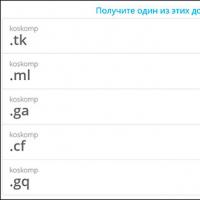 What is domain what problems may be
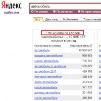 Yandex Wordstat: detailed instructions for using the service and grouping operators and a complicated request
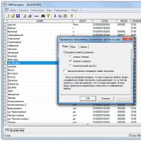 Editing DBF files
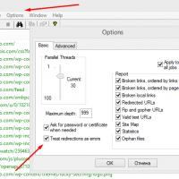 Xenu Link Sleuth - What is this program how to use the Xenu program
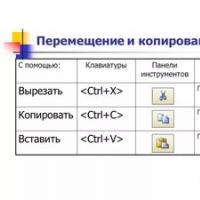 Methods Copy and insert text from keyboard without using mouse