The simplest low-frequency amplifiers on the transistors. Sound amplifier for car radio
The presented homemade amplifier works in Standard 2 + 1 (stereo + subwoofer). It is made on the basis of popular (and mainly cheap) chip, which gives output power About 30 W per channel with a load resistance of AC 4 Ohm and nutrition +/- 22V. The scheme is suitable for working with any standard source of audio signal: MP3 player, smartphone or computer, as it is equipped with a preamplifier with tone adjustments. The signal on the subwoofer is formed through the low-frequency active filter second order. The components of the signal above 200 Hz are trimmed, after which the signal comes to the power amplifier. The scheme can feed the voltage of no more than +/- 25 V.
Audio System Amplifier Scheme 2.1
The input signal is fed to the INP connector - the right channel, and the left channel on InL, passing through the high frequency filter consisting of C1 (1UF) and R1 (100K). The values \u200b\u200bof these elements provide a cutoff frequency of this filter at the level of about 1.5 Hz, which effectively cuts the constant component and too low frequencies. Next, the signal falls on the U3A (NE5532) amplifier (NE5532), and the elements R6 (10k) and R11 (4.7 K) provide a signal amplification at the level of about 1.5 (1 + 4.7 k / 10k). C6 condenser prevents excitement, while C2 (1UF) unleashes pre-amplifier U3A from the frequency adjustment system built on the U4A operating amplifier (NE5532).
Work of the Tembrobloka
Frequency adjustment is built classically, elements that make changes to the characteristics of the signal are in the negative loop feedback U4a microcircuits. At the resistance x1, C17 capacitors (4.7 NF), C20 (33NF) and resistor R7 (10K), "Half" P1a potentiometers (100K), P2a (100K) and elements R8 (10K) and R13 (3.3 K ). The resistance x2 is C18 capacitors (4.7 NF), C21 (33NF), resistor R9 (10K), "Half" P1a, P2A potentiometers and elements R8 and R13. Help understand can drawing Next:

When any of the P1A or P2A potentiometers sliders will be translated from its middle position - this will change the value of x1 and x2, and, therefore, the gain value becomes perfectly from -1 and starts depend on the frequency. Note that the values \u200b\u200bx1 and x2 always depend on the frequency, therefore it is fixed only in the case x1 \u003d x2.
P1A potentiometer is responsible for adjustment low frequencies. For high signal frequencies, the C20 and C21 capacitors are conductors, so that the adjustment using the potentiometer does not give any effect for these frequencies. P2A potentiometer allows you to adjust high frequencies, and due to C17 and C18 capacitors, it does not affect the bass adjustment. For low frequencies, C17 and C18 capacitors are opening due to which the potentiometer is disconnected from the diagram and its effect on regulation becomes insignificant.
The signal from the output of the temperature goes through R12 (4.7 K) to the potentiometer for adjusting the P3A volume (100K) and further on the UYU U5A (NE5532). Elements R14 (15K) and R15 (33K) are set to strengthen about -2 (-33k / 15k). From the U5A output, the signal via the R17 filter (100r), C3 (1UF) and R4 (100K) falls on the power amplifier input.
The boundary frequency of the filter for the subwoofer can be calculated using programs or changing the values \u200b\u200bof the elements experimentally.
The second channel of the preamp is similar to the passive elements in it, the resulting letter "A", and the potentiometers and operating amplifiers are labeled "b".
An additional module is an adder and an active low frequency filter, manufactured using the U6 operational amplifier (NE5532). The signal circuit selected in this part is used after appropriate amplification for sabwofer roll. The signal with both the outputs of the preamp falls through C22-C23 (220NF) and R2-R3 (100K) to the U6A input. P4 (220K) potentiometer allows you to adjust the gain with respect to the main volume regulator P3. P4, R2 and R3 together with U6A form an amplifier with an adjustable gain in the range of 0-2.2. The second operational amplifier (U6B) is an active low frequency filter. The values \u200b\u200bof the elements are chosen so that the system works as a second-order batterworth filter with boundary frequency in the 200 Hz region. The signal from the filter output through the C24 circuit (220NF), R5 (100K) falls on the power amplifier input.
UHC power supply

The entire amplifier feeds on a two-polar voltage in the range of 17-25 V. Power supply voltage for operating amplifiers is formed using stabilizers U1 (78L15 / L12), U2 (79L15 / L12) and filtered using C4-C5 (100UF) and C7-C8 containers ( 47UF). In addition, the power of each of the four operating amplifiers is smoothed using C9-C16 capacitors (100NF).
The work of the UMR assembly
Power amplifier is built on the basis of the popular U7 chip (TDA2050). This is probably the most common audio amplifier operating in class AB. With general harmonic distortions at the level of 0.5%, it allows you to achieve the power of about 30 W. Capacitor C8 (1UF) cuts off the constant component of the signal and at the same time is a high frequency filter at the input. R20 (22K) Determines the resistance at the input of the power amplifier.
The feedback circuit is R21 resistors (680R) and R22 (22K), the change in their ratio leads to a gain of the amplification, and the decrease in R22 or an increase in R21 causes a decrease in gain. In the Datashee chip TDA2050, the manufacturer recommends that it is more than 24 dB. Capacitor C29 (22UF) cuts off the constant component at the inlet of the amplifier. Resistor R19 (2.2 Ohm) and C32 capacitor (470NF) prevents self-excitation of the amplifier. Power UMPs Filter Capacitors C26-C27 (2200UF) and C30-C31 (100NF). The remaining two channels work similarly.
Assembly
The scheme rolls on a common printed circuit board. First of all, you need to get all the jumpers. Next can be proceeded to the soldering of resistors. All of which are 0.25 watts. Next, fasten the panels for operational amplifiers. At the very end, place voltage stabilizers on the board, electrolytic capacitors and potentiometers. When installing potentiometers, you should pay attention to the fact that they are on the same line - from aesthetic considerations. Metal potentiometer enclosures need to be connected to a mass using wires. It causes the shielding of the case of change of change, revealing the interference and background alternating current When touched by potentiometers to handles.

All three TDA2050 can be planted on a common radiator on which the potential of the negative power supply. To avoid this, apply insulating washers. You must be careful not to close the radiator on metal housing Mass amplifier.
The amplifier scheme is better to feed from a transformer with a power of about 100 W and 2x16 V voltage, rectifier and two capacitors filtering the change voltage.
Run and setting the scheme
When you first start, do not insert operating amplifiers in the panels and after turning on the power on, check that each panel has proper supply voltages. Then you can already bother them in places. The volume potentiometer should be twisted at a minimum (until left to the left), and the input must be filed from an MP3 player or computer. The amplifier works well as with speakers (speakers acoustic systems) with resistance 4 and 8 ohms.

In the role of output power amplifiers, the TDA2050, TDA2030 or TDA2040 chips are operating, providing output power, 14, 20 or 30 watts per channel, respectively. Not necessarily all chips amplifiers must be the same. You can establish those that weaker in the role of UNG stereo, and more powerful amplifier Leave for subwoofer.

Voltage stabilizers U1 and U2 provide symmetric two-polar stress at +/- 15 V.. You can successfully apply stabilizers to voltage 12 V or even 9 V. This will not cause changes in the preamp. Such a procedure will be necessary if we want to feed the amplifier with a smaller voltage than +/- 18 V. Stabilizers 7815 and 7915 may not want to work normally with a small voltage drop. Download printed circuit board files
Discuss the article stereo amplifier with subwoofer and FNH
I will immediately say, the assembly of this amplifier is justified only as an experiment, since the sound quality will be, at best, at the level of cheap, Chinese receivers - scanners. If someone wants to collect a low-power amplifier with more qualitative sound, with microcircuitTDA 2822 M. may go to the following link:
Portable Column for Player or Phone on the TDA2822M chip
Amplifier check photo:
The following figure shows a list of necessary parts: 
In the scheme, you can use almost any of the bipolar medium and high power transistors.n - P - N Structures, such as KT 817. The condenser at the entrance is desirable to put the film, with a capacity of 0.22 - 1 μF. An example of film capacitors in the following photo:
I bring a picture of the printed circuit board from the programSPRINT-LAYOUT: 
The signal is taken from the release of MP3 player or telephone, land and one of the channels are used. In the following figure you can see the plug of the jack 3.5 plug, for connecting to the signal source:
If desired, this amplifier, like any other, can be provided with a volume control, connecting the potentiometer to 50 kΩ according to the standard circuit, 1 channel is used:
Parallel to meals if in the power supply after diode Bridge There is no electrolytic capacitor of a large capacity, you need to put the electrolyte per 1000-2200 μF, with a working voltage greater than the voltage of the diagram.
An example of such a condenser:
Download pCB The amplifier on one transistor for the Sprint program - layout can be in the site section My files.
Assess the quality of the sound of this amplifier, you can watching the video of his work on our channel.
Buying nice laptop or cool phone, We rejoice in the purchase, admiring the set of features and speed of the device. But it is necessary to connect the gadget to the speakers to listen to music or watch a movie, we understand that the sound produced by the device, as they say "drove". Instead of full and clean sound, we hear a neuroent whisper with background noise.
But do not be upset and scold manufacturers, the problem with sound can be solved on your own. If you understand the chips and know how to solder well, you will not be difficult to make your own amplifier sound. In our article, we will tell how to make a sound amplifier for each type of device.
At the initial stage of work on creating an amplifier, you need to find tools and buy component parts. The amplifier circuit is manufactured on a printed circuit board with a soldering iron. To create chips, use special soldering stations that can be bought in the store. Using a printed circuit board allows you to make a device compact and easy to operate.
 Amplifier sound frequency
 Do not forget about the features of compact single-channel amplifiers based on the microcircuits of the TDA series, the main of which is the selection large number Heat. So try to internal device Amplifier, exclude microcircuit contact with other details. For additional cooling Amplifier, it is recommended to use a radiator grid for heat removal. The grid size depends on the model of the chip and the power of the amplifier. Place the place for the heat sink in advance in the amplifier housing.
Another feature independent manufacture Amplifier sound is low energy consumption. This in turn allows you to use the amplifier in the car by connecting it to the battery or on the road using the battery power. Simplified amplifier models require a voltage of the current only in 3 volts.
 The main elements of the amplifier
 If you are a novice radio amateler, then for more convenient work, we recommend that you take advantage of special computer Program - Sprint Layout. With this program you can create and view schemas on your computer. Note that the creation of your own scheme makes sense, only in that cases if you have sufficient experience and knowledge. If you are an inexperienced radio amateur, then use ready-made and proven schemes.
Below we will give the scheme and descriptions. different options Sound amplifier:
Headphone Sound Amplifier
Sound amplifier for portable headphones has no high power, but consumes very little energy. This is an important factor for mobile amplifiers that feed from batteries. Also on the device can be placed connector, to power from the network through the 3 volt adapter.
 Homemade Headphone Amplifier
 For the manufacture of an amplifier for headphones, you will need:
- Chip TDA2822 or analog KA2209.
- Amplifier assembly scheme.
- Capacitors 100 μF 4 pieces.
- Nest for headphone plug.
- Connector for the adapter.
- Approximately 30 centimeters of copper wire.
- Heat sink element (for a closed case).
 Headphone Amplifier Scheme
 The amplifier is made on the printed circuit board or mounted installation. Do not use in this form an amplifier. pulse transformerBecause it can be interfered. After making, this amplifier is able to provide a powerful and pleasant sound from the phone, player Go Tablet.
More than one option of the homemade amplifier for headphones, you can get acquainted in the video:
Laptop audio amplifier
The laptop amplifier is going in cases where the power of the dynamics built into it is not enough for normal listening, or if the speakers failed. The amplifier must be designed for external speakers up to 2 watts and winding resistance up to 4 ohms.
 Laptop audio amplifier
 To build an amplifier, you will need:
- Printed circuit board.
- TDA 7231 microcircuit.
- 9 volt power supply.
- Case for placement of components.
- Condenser non-polar 0.1 μF - 2 pieces.
- Condenser Polar 100 μF - 1 piece.
- Condenser Polar 220 μF - 1 piece.
- Condenser Polar 470 μF - 1 piece.
- Resistor permanent 10 com - 1 piece.
- Resistor constant 4.7 ohms - 1 piece.
- Switch two-position - 1 piece.
- The nest for entering the loudspeaker is 1 piece.
 Laptop audio amplifier circuit
 The order of assembly is determined independently depending on the scheme. The cooling radiator must be of this size to working temperature inside the amplifier housing did not exceed 50 degrees Celsius. If you plan to use the device outdoors, it is necessary to make a housing with holes for air circulation. For the housing, you can use a plastic container or plastic boxes from under the old radio equipment.
You can view visual instructions in the video:
Sound amplifier for car radio
This amplifier for the car radio is assembled on the TDA8569Q chip, the scheme is not complicated and very common.
 Sound amplifier for car radio
 The microcircuit has the following stated characteristics:
- Input power 25 watts per channel in 4 ohms and 40 watts per channel in 2 ohms.
- Power supply 6-18 volts.
- Range of reproducible frequencies of 20-20000 Hz.
For use in the car, the diagram must add a filter from interference that are created by the generator and the ignition system. The microcircuit also has protection against short circuit At the outlet and overheating.
 Sound Amplifier Scheme for AvtoGNITOL
 Checking with the presented scheme to purchase the necessary components. Next, draw a printed circuit board and drill holes in it. After that, spend the board with chlorine iron. In conclusion, Ludim and begin to solder microcircuit components. Note that the pathways of the power is better to cover the thicker layer of the solder so that there are no evidence for food.
On the chip need to install the radiator or organize active cooling with the help of a kuller, otherwise, with an increased volume, the amplifier will overheat.
After assembling the chip, you need to make a power filter according to the following scheme:
 Filter Filter Scheme
 The throttle in the filter dulls in 5 turns, with a wire with a cross section of 1-1.5 mm, on the faith ring with a diameter of 20 mm.
Also, this filter can be used if your tape recorder catches "pressing".
Attention! Be careful and do not confuse the polarity of the power, otherwise the microcircuit is combined instantly.
How to make an amplifier for stereo signal, you can also learn from the video:
Sound amplifier on transistors
As a scheme for transistor amplifier Use the diagram below:
 Sound transistor audio amplifier
 The scheme, though old, but has a lot of fans, for the following reasons:
- Simplified installation due to the small number of elements.
- There is no need to sort out transistors into complementary pairs.
- 10 watt power, with a margin enough for residential rooms.
- Good compatibility with new sound cards and players.
- Excellent sound quality.
Start assembling a power amplifier. Divide the two channels for stereo with two secondary windings running from one transformer. On the layout, make bridges on Schottky diodes for rectifier. After the bridges are CRC filters from two capacitors of 33,000 Igf and between them a resistor 0.75 ohms. The filter resistor needs a powerful cement, with a sheek current to 2a, it will dispel 3 W heat, so it is better to take with a reserve of 5-10 W. The rest of the resistors in the scheme, the power of 2 W will be enough.
 Amplifier on transistors
 Go to the boost of the amplifier. All except the weekend transistors TR1 / TR2 is located on the board itself. Output transistors are mounted on radiators. Resistors R1, R2 and R6 are better to first put rapidly, after all adjustments to fall, measure their resistance and solder final constant resistors with similar resistance. The setting is reduced to the following operations - with R6 is set to the voltage between X and zero to be exactly half of the voltage + v and zero. Then, with the help of R1 and R2, a rest current is exhibited - we put a measurement tester direct current And measure the current at the Power Supply point. The rest of the amplifier in the class A maximum and in fact, in the absence of an input signal, everything goes into thermal energy. For the 8-ohmic columns, this current must be 1.2 and at a voltage of 27 volts, which means 32.4 Watt heat per channel. Since the current setup may take a few minutes, the weekend transistors must already be on cooling radiators, otherwise they will quickly overheat.
When adjusting and understating the resistance of the amplifier, the frequency of the CBC can grow, so it is better to use 5.5 μF for the inlet capacitor, and 1 or even 2 μF in the polymer film. It's believed that this scheme Not prone to self-excitation, but just in case, between the point X and the earth, the Tsobel chain is set: R 10 Ohm + C 0.1 μF. Fuses need to be placed both on the transformer and on the power input of the circuit.
A good idea will be the use of the thermal paste for maximum contact between the transistor and the radiator.
Now a few words about the case. The size of the housing is set by radiators - NS135-250 at 2500 square centimeters per transistor. The hull itself is made of plexiglas or plastics. Collect the amplifier before starting to enjoy the music, it is necessary to minimize the background to properly divorce the land. To do this, attach the SZ to the minus of the login, and output the remaining minus to the "star" near the filter condensers.
 Sound amplifier case on transistors
 approximate cost supplies For transistor audio amplifier:
- Filter condensers 4 pieces - 2700 rubles.
- Transformer - 2200 rubles.
- Radiators - 1800 rubles.
- Weekend transistors - 6-8 pieces of 900 rubles.
- Small elements (resistors, condensers, transistors, diodes) around - 2000 rubles.
- Connectors - 600 rubles.
- Plexiglas - 650 rubles.
- Paint - 250 rubles.
- Board, wires, solder about - 1000 rubles
As a result, the amount is 12,100 rubles.
You can also watch a video amplifier assembly video on Germany transistors:
Lamp sound amplifier
Simple simple lamp amplifier Consists of two cascades - a pre-amplifier on a 6N23P and power amplifier at 6P14P.
 Lamp amplifier circuit
 As can be seen from the scheme, both cascades work in a triotode inclusion, and the anode current of the lamps is close to the limit. Currents are built up with cathode resistors - 3ma for the input and 50mA for the output lamp.
Details used for the lamp amplifier must be new and high Quality. The permissible deviation of the resistor denominations may be plus-minus 20%, and the capacity of all capacitors can be increased by 2-3 times.
Filter capacitors must be calculated on voltage at least 350 volts. An intercountable capacitor should be calculated for the same tension. Transformers for the amplifier can be ordinary - TV31-9 or more modern analog - TWSE-6.
 Lamp sound amplifier
 The volume and stereo balance controller to the amplifier is better not to install, since the adjustment data can be made in the computer or player. The entrance lamp is selected from - 6N1P, 6N2P, 6N23P, 6H3P. 6P14P, 6P15P, 6P18P or 6P43P (with increased resistance of the cathode resistor) are used as the output penter.
Even if you have a working transformer, it is better to use a conventional transformer with a 40-60 watt rectifier for the first turning on the paw amplifier. Only after successful testing and adjustment of the amplifier can be installed a pulse transformer.
Use the standard for plugs and cables to connect the speakers to install "pedalings" to 4 contacts.
The housing for the paw amplifier is usually made from the shell old technique or case blocks.
Another option of the lamp amplifier you can see the video:
Classification of sound amplifiers
So that you can determine which class of sound amplifiers belongs to the device you collected, check out the classification of UMPs below:
 Amplifier class A.
 - Class A. - The amplifiers of this class work without cut-off at the linear portion of the voltamper characteristics of the amplifying elements, which ensures minimum of nonlinear distortion. But for this you have to pay a large amplifier size and a huge power consumed. The CPD of the class A amplifier is only 15-30%. This class includes lamp and transistor amplifiers.
 Class B Amplifier
 - Class B. - Class amplifiers in work with a cut-off signal of 90 degrees. For this operation mode, a two-stroke scheme is used, each part enhances its half of the signal. The main minus class B amplifiers is the distortion of the signal due to the step transition of one half-wave to the other. Plus this class The amplifiers consider the high efficiency, sometimes reaching 70%. But despite the high performance, modern models of the class B amplifier, you will not meet on the shelves.
 AV. A amplifier
 - Class AU. - This is an attempt to combine the amplifiers described above, in order to achieve the lack of signal distortions and a high efficiency.
 Amplifier class N.
 - Class N. - Developed specifically for cars, which have a voltage limit that feeds output cascades. The reason for creating amplifiers of class N is the fact that the real sound signal It has a pulse character and its average power is much lower than peak. The scheme of this class of amplifiers is based on simple scheme For AB amplifier, working on a pavement scheme. Only a special supply voltage doubling scheme has been added. The main element of the doubling scheme is a cumulative capacitor of a large capacity, which is constantly charging from the main power source. At power peaks, this capacitor connects the control circuit with the main power source. The supply voltage of the output stage of the amplifier doubles, allowing it to cope with the transmission of the signal peaks. The efficiency of class H amplifiers reaches 80%, while distorting the signal is only 0.1%.
 Amplifier class D.
 - Class D is separate class Amplifiers called - "Digital amplifiers". Digital transformation provides additional features Sound processing: from adjusting the volume and timbre to the implementation of digital effects, such as reverb, noise suppression, acoustic feedback. Unlike analog amplifiers, the output signal of the class D amplifiers is a rectangular pulse. Their amplitude is constant, and the duration varies depending on the amplitude of the analog signal entering the input of the amplifier. The efficiency of this type of amplifiers can reach 90% -95%.
In conclusion I would like to say that the activity of electronics requires a large amount of knowledge and experience that are purchased for a long time. Therefore, if something has not happened, do not be discouraged, reinforce your knowledge from other sources and try again!
Hello everyone!
The main acoustics system of my computer are SVEN SPS-821. Quality is enough, volume too. Basins in principle, too, but only on a small volume. I want to do about louder - and Sab can no longer squeeze out more, bass becomes weak. I decided to take autosab + there are speakers of Vega 15As-109. The amplifier took the class D - the dimensions decide, not arrogant to the power, the price is not very high.
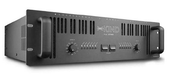
Characteristics
work voltage 12 V-25 V.As usual - the maximum power is indicated taking into account the company 10%.
Left and right channel 50WX2 (max.),
Exit to the subwoofer 100 W (max.), Efficiency can reach more than 90%
The total harmonic distortion coefficient (THD + noise: 0.1% @ 50 W, Ohm, \u003d 21 V
Load resistance: 4ohm
SNR 89 (dB)
Dynamic range: 100DB
Power: 200 W
A box of 35 mm * 90 mm * 108 mm, made of metal. 
On the front panel switch, and 3 regulators - speaker volume control, subwoofer volume control and general volume control. 
Rear connectors - Jack 3.5, power (plug 5.5 * 2.5mm), and connectors for connecting columns. It would be more convenient for me if they were spring type. 
Rubber legs are glued at the bottom to not slip 
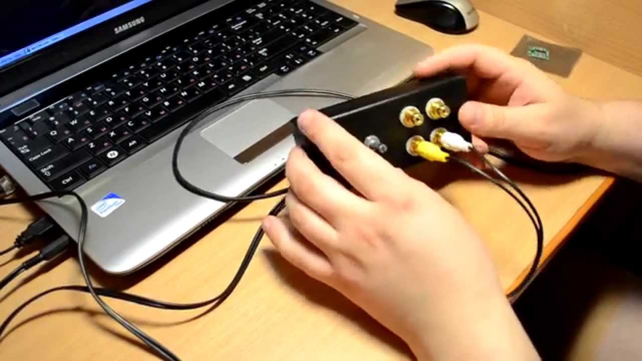
Disassembly.
Disassemble the device is easier than simple - unscrew the screws, but remove the lid.
General form 
By nutrition, the capacitor is 3300MKF 25 volt. The Chinese even put the greater capacitance. But there is almost no stock in voltage, but if you feed from the power unit of the laptop (19V), then in principle anything terrible. 
2 NE5532P chips, 2-channel, low-noise operational amplifier, 10 MHz, ± 15V, 9V / μs. I myself do not understand this, just arrived) 
Connectors connecting columns. 
Radiator with chokes. 
Puting the amplifier from a laptop power supply of 19V 4,74A. In the future I will save from 24V, the power supply is driving.
I connected the speakers (Vega 15As-109), even Sab (IceFire125 - 180W) car bought, always wanted him) 

Turn on ... and then how to jumped out the spark from the power connector! She was crushed, but then I understood it - it was so charged the capacitor. Well, OK.
The LED lights up, but when switching the ON-OFF switch, it does not go out, but the sound turns off the MUTE mode. 
Listened to how it plays. Plays normally, no distortion. Honestly did not expect such volume from the Soviet columns) Sab 180W swaying well.
I liked the separate adjustment - you can drop the volume of the speakers, but add the volume of the Saba to get powerful bass.
In general, the home is a great option.
Consumption at high volume 60-70 watts.
Here it did not check the heating, you will not understand the case, but there was no disconnection on high volume.
In the video you can listen to how it plays, but the camera microphone does not convey the quality (
I liked the amp, the capacity for the house is more than enough.
And the amplifier itself is small, so it will be perfectly located on my computer desk.
All good!
I plan to buy +38. Add to favourites I liked the review +22 +47Typical errors in the design of germanium amplifiers occur due to desire, get a wide bandwidth, small distortion from the amplifier, etc.
I bring the scheme of my first German amplifier designed by me in 2000.
Although the scheme is fully operational, its sound qualities leave much to be desired.

Practice has shown that the use of differential cascades, current generators, cascades with dynamic load, current mirrors and other tricks with OOS do not always lead to the desired result, and sometimes just lead to a dead end.
The best practical results for high sound quality, gives the use of one-bit stage stages. Strengthening and use of inter-cascade matching transformers.
Presented to your attention germany amplifier With an output capacity of 60 W, on the load of 8 ohms. Output transistors used in the P210A, P210SH amplifier. Linearity 20-16000 Hz.
The subjective lack of high frequencies is practically not felt.
When the 4th load, the amplifier issues 100W.
Amplifier circuit on P-210 transistors.
The amplifier is powered by non-stabilized, power supply with output, two-polar voltage +40 and -40 volts.
For each channel, a separate bridge from D305 diodes is applied, which are installed on small radiators.
Filter capacitors, it is desirable to apply at least 10000 mk to the shoulder.
Power transformer data:
- Zhelezo 40 to 80. Primary winding Contains 410 WIT. Wires 0.68. Secondary 59 WIT. Wires 1.25 wound four times (two windings - the top and bottom shoulder of one channel amplifier, the remaining two - the second channel)
Additional on the power transformer:
Iron W 40 for 80 from the KVN TV power supply. After the primary winding, a copper foil screen is installed. One unlocked turning. It turns out the output that is then grounded.
You can use any, appropriate with iron.
The consigning transformer is made on the Item C20 per 40.
The primary winding is divided into two parts and contains 480 WIT.
The secondary winding contains 72 turns and dulls in two wires at the same time.
First, 240 waters are wound up, then seconds, then 240 twit twit again.
The diameter of the primary wire is 0.355 mm, seconders 0.63 mm.
The transformer is collected in the joint, the clearance is a cable paper strip of about 0.25 mm.
The resistor 120 ohms is enabled for the guaranteed absence of self-excitation when the load is disconnected.
The chains 250 ohm +2 to 4.7 ohms serve to supply the initial displacement to the base of the output transistors.
With the help of 4.7 ohm trimming resistors, the current of rest is installed 100mA. On resistors in the emitters of the output transistors of 0.47 ohms, there should be a voltage, a value of 47 mV.
Weekend transistors P210, should be at the same time, almost barely warm.
For accurate installation of zero potential, resistors 250 ohms should be accurately selected (in a real design consist of four resistors for 1 com 2W).
For the smooth installation of the rest current, the R18, R19 types of SP5-3B type 4.7 Ohm is used.
The appearance of the rear amplifier is depicted in the photo below.

You can find out your impressions of this amplifier's sound, in comparison with the previous non-vertical option for P213-217?
An even more saturated juicy sound. Especially emphasized the quality of bass. Listening was conducted by S. open acoustics On the 2A12 speakers.
- Jean, but why exactly p215 and p210, and not gt806 / 813 in the scheme?
Carefully see the parameters and characteristics of all these transistors, I think you will understand everything, and the question disappears by itself.
I clearly realize the desire of many, make a German amplifier to more broadband. But the reality is such that for sound purposes many high-frequency germany transistors Not quite suitable. From the domestic I can recommend P201, P202, P203, P4, 1T403, GT402, GT404, GT703, GT705, P213-P217, P208, P210. The bandwidth expansion method is the use of circuits with a common base, or the use of import transistors.
The use of transformer schemes made it possible to achieve excellent results and on silicon. Developed an amplifier for 2N3055.
I will share in the near future.
- And what's from "0" at the exit? With a current of 100 mA, it is difficult to believe that it will be able to keep it in the process of operation in acceptable + -0.1 V.
In similar 30-year-old schemes (Grigorieva scheme), it is solved either a "virtual" midwater or electrolyte:
Amplifier Grigoriev.

Zero potential is held in the limit you specified. The rest of rest can be done and 50mA. Controlled on the oscilloscope until the step is disappeared. No more need. Next, all OU easily work on the load 2k. Therefore, there are no special problems of matching with CD.
Some high-frequency Germany transistors require an additional study of them in sound schemes. 1T901A, 1T906A, 1T905A, P605-P608, 1Ts609, 1T321. Try, work experience.
Sometimes there was a sudden failure of transistors 1T806, 1T813, so I can recommend them with caution.
They need to put "fast" current protection, designed for current greater maximum in this scheme. To avoid protection in normal mode. Then they work very reliably.
I will add my version of the Grigoriev scheme
The version of the Grigoriev amplifier scheme.

The selection of the resistor from the database of the input transistor is installed half of the supply voltage at the point of connection of the resistors 10. The selection of the resistor parallel to the 1N4148 diode, the reservoir current is installed.
- 1. In my reference books, D305 is normalized by 50V. Can safer apply D304? I think 5a is enough.
- 2. Specify the real H21 for devices installed in this layout or their minimum-required values.
You are absolutely right. If there is no need for high power. On each diode, the voltage is about 30 V, so there are no problems with reliability. Transistors were applied with the following parameters; P210 H21-40, P215 H21-100, GT402G H21-200.
 How to reflash iPhone with PC and iTunes
 Best Bitcoin Wallets for iOS Download application wallet on iPhone
 Lenovo Vibe X2 Description, Features, User Reviews
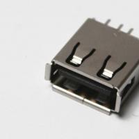 The computer does not see the flash drive: causes and solving the problem
 About Windows Update From Wannacry Encrypter Virus
 Hot browser keys
 New Mac Mini turned out to be five times more powerful than the predecessor