Simple unch on transistors. Simple germanium power amplifier. Availability of distortions in various classes of LF-amplifiers
Now on the Internet you can find a huge number of circuits of various amplifiers on chips, mainly the TDA series. They possess quite good characteristics, good efficiency and are not so expensive, in connection with this, and are so popular. However, in their background, transistor amplifiers, which, although complex in the setting, are not less interesting are forgotten.
Amplifier scheme
In this article, consider the assembly process a very unusual amplifier working in the class "A" and containing only 4 transistors. This scheme was developed back in 1969 by the English engineer John Linsley, despite his old age, she still remains relevant to this day.Unlike chip amplifiers, transistor amplifiers require a thorough setting and selection of transistors. This scheme is no exception, even though it looks extremely simple. Transistor VT1 - input, PNP structure. You can experiment with various low-power PNP transistors, including Germany, for example, MP42. It has been well proven in this scheme as VT1 such transistors as 2N3906, BC212, BC546, CT361. The transistor VT2 is the structure of NPN, medium or low power, CT801, KT630, CT602, 2N697, BD139, 2Sc5707, 2SD2165 are suitable. Particular attention should be paid to the output transistors VT3 and VT4, or rather, their gain. CT805, 2SC5200, 2N3055, 2SC5198 are well suited here. You need to select two identical transistors with as close as possible gain as possible, and it should more than 120. If the gain of the output transistors is less than 120, it means that the transistor with a large amplification (300 or more) must be put into the drive cascade (VT2).
Selection of rates of amplifier
Some denominations on the diagram are selected based on the supply voltage and load resistance, some possible options are shown in the table:
It is not recommended to raise the supply voltage of more than 40 volts, the output transistors may fail. The feature of the amplifiers of class A is a long rest current, and, therefore, a strong heating of transistors. With a supply voltage, for example, 20 volts and a rest of 1.5 amper, the amplifier consumes 30 watts, regardless of whether the signal is fed to its input or not. Each of the weekend transistors will dispel 15 watts heat, and this is the power of a small soldering iron! Therefore, the VT3 and VT4 transistors must be installed on a large radiator using a thermalcol.
This amplifier is inclined in the emergence of self-excitation, therefore the Tsobel chain is set at its output: a resistance resistor 10 ohms and a capacitor 100 NF, included in series between the ground and the common point of the output transistors (this chain is shown in the diagram).
When the amplifier is first turned on, it is necessary to enable an ammeter to control the rest of the rest. While the output transistors did not warm up to the operating temperature, it can swim a little, it is quite normal. Also, when you first turn on, you need to measure the voltage between the total point of the output transistors (collector VT4 and Emmitizer VT3) and the Earth, there should be half the supply voltage. If the voltage is different in a large or smaller side, you need to twist the R2 trick resistor.
Amplifier board:
(Dropping: 605)
The board is made by the LUT method.
I assembled amplifier


A few words about condensers, entrance and output. The capacitance of the input capacitor in the diagram is indicated by 0.1 μF, but this container is not enough. As an input, a film capacitor with a capacity of 0.68 - 1 μF should be supplied, otherwise a unwanted low-frequency cut is possible. The output capacitor C5 is worth taking the voltage not less than the supply voltage, it is also not worth greeding with a container.
The advantage of the scheme of this amplifier is that it does not represent hazards for the speakers of the speaker system, because the speaker is connected through a separator capacitor (C5), which means that when the constant voltage appears, for example, when the amplifier exits, the speaker will remain intact, After all, the capacitor will not miss a constant voltage.
Amplifier on one transistor - Here is the design of a simple UNG on one transistor. It is from such schemes that many radio amateurs started their way. Once by collected a simple amplifier, we always strive to make a more powerful and high-quality device. And so everything goes on the growing, there is always a desire to make an impeccable power amplifier.
The simplest amplifier diagram shown below is made on one bipolar transistor and six electronic components, including speaker. This design of the device reinforcing low frequency sound is created just for beginner radio amateurs. Its main purpose is to give to understand the simple principle of operation of the amplifier, so it is collected using the minimum number of radio-electronic elements.
This amplifier naturally has a small power, for a start it is big and not needed. However, if you install a more powerful transistor and raise a little power supply, then approximately 0.5 watts can be obtained at the output. And this is already considered a fairly decent power for an amplifier having such a design. In the scheme, a bipolar transistor with N-P-N conductivity was used for clarity, you can use any and with any conductivity.
To get 0.5 W at the exit, it is best to apply powerful bipolar transistors of the KT819 type or their foreign counterparts, for example 2N6288, 2N5490. You can also use firm transistors type KT805 them foreign analog - BD148, BD149. The condenser in the output circuit can be set 0.1MF, although its nominal value does not play a large role. Nevertheless, it forms the sensitivity of the device relative to the frequency of the beep.
If you put a capacitor with a large container, then at the output will be predominantly low frequencies, and high will be cut off. And on the contrary, if the container is small, low frequencies will be cut, and high skipping. Therefore, this output capacitor is selected and set on the basis of your preferences regarding the audio range. The supply voltage for the diagram should be selected from the range from 3V - to 12V.
I would also like to clarify - this power amplifier is submitted to you only for demonstration purposes, to show the principle of operation of such a device. The sound of this device will certainly be at a low level and does not matter any comparison with high-quality devices. When the playback volume is gained, distortions will occur in the dynamics.
In Habré, there were already publications about DIY lamp amplifiers, which were very interesting to read. There is no dispute, the sound of them is wonderful, but for everyday use it is easier to use a device on transistors. Transistors are more convenient because they do not require warm-up before work and more durable. Yes, and not everyone will risk starting a lamp SAGA with anodic potentials at 400 V, and transformers for transistor a couple of dozen volts are much safer and just more affordable.
As a schema for playback, I chose a scheme from John Linsley Hood 1969, taking copyright parameters in the calculation of the impedance of its columns of 8 ohms.
The classic scheme from the British engineer, published almost 50 years ago, is still one of the most reproducible and collects exclusively positive feedback about himself. There are many explanations for this:
- The minimum number of elements simplifies installation. It is also believed that the simplest design, the better the sound;
- despite the fact that weekend transistors are two, they should not be sought in complementary pairs;
- 10 watt weekend with a margin enough for conventional human dwellings, and the input sensitivity of 0.5-1 volts is very well consistent with the release of most sound cards or players;
- Class A - He and Africa class A, if we are talking about good sound. Compared with other classes will be slightly lower. 
Inner design
The amplifier begins with meals. The separation of two channels for stereo is more correct to lead from two different transformers, but I was limited to one transformer with two secondary windings. After these windings, each channel exists in itself, so it is necessary not to forget to multiply by two of all that mentioned below. On the layer we make bridges on Schottky diodes for rectifier.
It is possible on conventional diodes or even ready-made bridges, but then they must be shunting capacitors, and the voltage drop on them is greater. After the bridges are CRC filters from two capacitors of 33,000 Igf and between them a resistor 0.75 ohms. If you take less and container, and the resistor, the CRC filter will become cheaper and is heated less, but the pulsation will increase, which is not Comilfo. These parameters, IMHO, are reasonable from the point of view of the price-effect. The filter resistor needs a powerful cement, with a sheek current to 2a, it will dispel 3 W heat, so it is better to take with a reserve of 5-10 W. The remaining resistors in the 2 W power scheme will be quite enough.
Next, go to the boost of the amplifier. A bunch of ready-made whales is sold in online stores, but no less and complaints about the quality of Chinese components or illiterate wiring on boards. Therefore, it is better for himself, under the same "scatter". I made both channels on a single layer to then attach it to the bottom of the housing. Starting with test elements:

All except the weekend transistors TR1 / TR2 is located on the board itself. Weekend transistors are mounted on radiators, it is slightly lower. To the author's scheme from the original article need to make such remarks:
Not everyone needs to immediately spread tightly. Resistors R1, R2 and R6 are better to first put rapidly, after all adjustments to fall, measure their resistance and solder final constant resistors with similar resistance. Setup is reduced to the following operations. First, with the help of R6, the voltage between x and zero is exactly half of the voltage + v and zero. In one of the channels I did not have 100 com, so it is better to take these tricks with a margin. Then with the help of R1 and R2 (retaining their approximate ratio!) The rest current is exhibited - we put the DC measurement tester and measure this very current at the Power Input Power Power. I had to significantly reduce the resistance of both resistors to obtain the desired reservoir. The rest of the amplifier in the class A maximum and in fact, in the absence of an input signal, everything goes into thermal energy. For the 8-ohm columns, this current, according to the author's recommendation, should be 1.2 and at a voltage of 27 volts, which means 32.4 heat watts per channel. Since the current setup may take several minutes, then the weekend transistors must already be on cooling radiators, otherwise they will quickly overheat and die. For they bask basically.
It is possible that in the order of the experiment, it will want to compare the sound of different transistors, so it is also possible to leave the possibility of a convenient replacement. I tried at the entrance 2n3906, CT361 and BC557C, there was a small difference in favor of the latter. In the prestigious, KT630, BD139 and KT801 were tried, stopped at imported. Although all of the above transistors are very good, and the difference may be more subjective. At the output, I put 2N3055 at once (St Microelectronics), as they like many.
When adjusting and understating the resistance of the amplifier, the frequency of the CBC can grow, so it is better to use 5.5 μF for the inlet capacitor, and 1 or even 2 μF in the polymer film. On the network, the Russian picture scheme "Ultra-linear amplifier class A" is still walking, where this capacitor is generally proposed as 0.1 μF, which is fraught with a cut of all bass under 90 Hz:

It is written that this scheme is not prone to self-excitation, but just in case there is a chain of Tsobel between the point X and the Earth: R 10 Ohm + with 0.1 μF.
- Fuses, they can and need to be placed on both the transformer and the power input of the circuit.
- It will be very appropriate to use the thermal paste for maximum contact between the transistor and the radiator.
Plumbing and carpentry
Now about the traditionally complex part in DIY - case. The enabarits of the hull are set by radiators, and they in the class A should be large, remember the 30 watt heat on each side. At first, I disadvantaged this power and made a body with medium radiators 800cm² per channel. However, at the time of the rest of 1.2a, they heard up to 100 ° C for 5 minutes, and it became clear that something more powerful needed. That is, you need to either put raw radiators or use coolers. I didn't want to make a quadrocopter, so giant handsome hands HS 135-250 with an area of \u200b\u200b2500 cm² for each transistor were purchased. As practice has shown, such a measure turned out to be a little excessive, but now the amplifier can be calmly torn with his hands - the temperature is only 40 ° C, even in rest mode. A certain problem was the drilling of holes in the radiators under fastenings and transistors - initially purchased Chinese rolling rolled metal drilled extremely slowly, it would be left for each hole at least half an hour. Cobalt swells came to the rescue with a sharpening angle of 135 ° from the famous German manufacturer - each hole is held in a few seconds!I myself made the body from the plexigla. We order in the glazers immediately sliced \u200b\u200brectangles immediately, we carry out the necessary holes for fasteners and paint on the reverse side of the black paint.


Painted on the back of the plexiglass looks very beautiful. Now it remains only to collect everything and enjoy the music ... Oh yeah, with the final assembly, it is still important to minimize the background correctly divorce the land. As it was clarified over decades to us, C3 must be attached to the signal ground, i.e. To minus entrance, and all other minuses can be sent to the "star" near the filter capacitors. If everything is done correctly, then no background is not to hear, even if the ear to bring the ear on the maximum volume. Another "earthy" feature, which is characteristic of sound cards, not unleashed with a computer galvanically - this is a disturbance with a motherboard that can crawl through USB and RCA. Judging by the Internet, the problem occurs often: in the speakers you can hear the sounds of the work of the HDD, printer, mice and the background of the Systems BP. In this case, the easiest way to break the earthen loop, taking the ground with a heating on the amplifier fork. There is nothing to fear here, because There will be a second grounding circuit through a computer.
The volume control on the amplifier I did not do, because it was not possible to get any high-quality ALPS, but I did not like the rustling of Chinese potentiometers. Instead, an ordinary 47 kΩ resistor was installed between the "Earth" and the "Signal" of the entrance. Moreover, the regulator has an external sound card at hand, and in each program, too, there is a slider. The volume controller is not only at the vinyl player, so for listening to it, I attached an external potentiometer to the connecting cable.

I guess this container in 5 seconds ...
Finally, you can proceed to listening. Foobar2000 → ASIO → External ASUS Xonar U7 are used as a sound source. MICROLAB PRO3 columns. The main advantage of these columns is a separate block of own amplifier on the LM4766 chip, which can be immediately removed somewhere away. Much more interesting with this acoustics sounded the amp from the Panasonic mini-system with a proud Hi-Fi inscription or an amplifier of the Soviet Player Vega-109. Both of the above-mentioned devices work in the AB class. The JLH submitted in the article has shifted all of the above-mentioned comrades in one gate, according to the results of the blind test for 3 people. Although the difference was audible with the unarmed ear and without any tests - the sound is clearly more detailed and more transparent. It is very easy, for example, to hear the difference between MP3 256Kbps and FLAC. I used to think that the Lossless effect is greater as a placebo, but now the opinion has changed. Similarly, it was much more pleasant to listen to the uncompressed from Loudness War files - Dynamic Range less than 5 dB at all is not ice. Linsley-Hood is worth the cost of time and money, for a similar branded amp will cost much more expensive.Material costs
Transformer 2200 r.Weekend transistors (6 pcs. With reserve) 900 p.
Filter capacitors (4 pcs) 2700 p.
"Passage" (resistors, small capacitors and transistors, diodes) ~ 2000 p.
Radiators 1800 p.
Plexiglas 650 r.
Paint 250 r.
Connectors 600 p.
Boards, wires, silver solder, etc. ~ 1000 p.
Total ~ 12100 r.
Reading time ≈ 6 minutes
Amplifiers are probably one of the first devices that begin to design radio amateurs. Collecting UMLC on transistors with their own hands with the help of a finished scheme, many use chips.
Transistor amplifiers although they differ in a huge number, but each radio electroner is constantly seeking to do something new, more powerful, more complex, interesting.
Moreover, if you need a high-quality, reliable amplifier, it is worth looking towards the transistor models. After all, it is they who are the most cheap, are able to produce clean sound, and they can easily construct any newcomer.
Therefore, let's figure out how to make a homemade Amplifier of the LF Class B.
Note! Yes, yes, class amplifiersB can also be good. Many say that only lamp devices can be issued high-quality sound. Partly this is true. But take a look at their cost.

Moreover, assemble such a device at home - the task is not from the lungs. After all, you will have to look for the right radiologines for a long time, then buy them at a fairly high price. Yes, and the process of assembly and soldering itself requires some experience.
Therefore, we consider a simple scheme, and at the same time a high-quality low frequency amplifier capable of issuing sound power 50 W.

Old, but tested by the years scheme from the 90s
The UNF scheme, which we will collect, was first published in the Radio magazine for 1991. She was successfully gathered hundreds of thousands of radio amateurs. Moreover, not only for and improving skill, but also for use in their audio systems.
So, the famous low frequency amplifier Dorofeeva:

The uniqueness and genius of this scheme lies in its simplicity. This UHC uses the minimum number of radio elements, and an extremely simple power source. But, the device is able to "take" the load in 4 Ohm, and provide an output power of 50 W, which is quite enough for a home or automotive acoustic system.
Many electrical engineering improved, refined this scheme. I. For convenience, we took the most modern item, replacing the old components to new, so that you could easier design UCH:

Description Low Frequency Amplifier Scheme
In this "recycled" Doroveevsky UNG, unique and most effective schematic solutions were used. For example, resistance R12. This resistor limits the current on the output transistor collector, thereby limiting the maximum power of the amplifier.
Important! Do not change the nominalR12 to increase output power, as it is submitted precisely under the components that are used in the scheme. This resistor protects the entire short circuit circuit.

Output cascade of transistors:

The same R12 "live":

The R12 resistor must have a capacity of 1 W, if there is no such thing at hand - take it to the POLVATT. It has parameters that provide the coefficient of nonlinear distortions to 0.1% at a frequency of 1 kHz, and not more than 0.2% at 20 kHz. That is, you will not notice any changes for rumor. Even when working at maximum power.
The power supply of our amplifier must be chosen two-pepolar, with output voltages in the range of 15-25 V (+ - 1%):

To "raise" the sound power, you can increase the voltage. But, then you will have to replace the transistors in the terminal cascade of the scheme. It is necessary to replace them on more powerful, after which it recalculates several resistance.

The components R9 and R10 must have a denomination, in accordance with the applied voltage:

They, with the help of Stabilon, limit the passing current. In the same part of the chain, a parametric stabilizer is collected, which is needed to stabilize voltage and current before operating amplifier:


A couple of words about the chip TL071 - "Heart" of our UNG. It is considered an excellent operating amplifier, which is found in both amateur structures and professional audio equipment. If there is no suitable operator, it can be replaced by TL081:

View "In reality" on the board:

Important! If you decide to apply any other operating amplifiers in this scheme, carefully study their pinout, because the "legs" can have other values.
For convenience, the chip TL071 is to mount the plastic panel pre-soldered in the board. So it will be possible to quickly replace the component on another if necessary.
Good to know! To get acquainted to introduce you another scheme of this UNG, but without a reinforcing chip. The device consists exclusively of transistors, but is assembled extremely rarely due to obsolescence and irrelevance.

To make it more convenient, we tried to make a minimum printed circuit board - for compactness and ease of installation in the audio system:


All jumpers on the board are needed immediately after etching.
Transistor blocks (input and output cascades) must be mounted on a common radiator. Of course, they are carefully isolated from the heat sink.
In the diagram they are here:

And here on the printed circuit board:

If there are no ready-made available, radiators can be made of aluminum or copper plates:

The output cascade transistors must have a dispersible power of at least 55 W, and even better - 70 or as much as 100 W. But this parameter depends on the supply voltage-based on the board.


From the scheme it is clear that 2 complementary transistors are used at the input and output cascade. It is important for us to choose them in a reinforcing coefficient. To determine this parameter, you can take any multimeter with the transistor check function:


If you do not have such a device, then you will have to borrow from some masters the transistor tester:


Stabilians should be selected by power on the POLVATT. The stabilization voltage should be 15-20 V:


Power Supply. If you plan to mount a transformer BP on your UNG, then select the capacitors filters with a capacity of at least 5,000 microns. Here the bigger - the better.


We collected low frequency amplifier refers to the B-class. It works stably, providing almost crystal-pure sound. But, BN is best selected so that it can not work for all power. The optimal option is a transformer with an overall power of at least 80 W.
That's all. We figured out how to assemble the UNG on the transistors with their own hands using a simple scheme, and how in the future it can be improved. All components of the device will be found, and if they are not - it is worth disassembling a couple of old tape recorders or order radio components on the Internet (they are practically a penny).
Going into the past, and now to collect any simple amplifier, no longer need to suffer with calculations and rivet the printed circuit board of large sizes.
Now almost all cheap reinforcement is done on chips. The largest distribution was obtained by the TDA chips to enhance the audio signal. Currently, they are used in car radio, in active subwoofers, in home acoustics and in many other audiors and look like this:


Pluses of TDA chip
- In order to assemble the amplifier on them, it is enough to supply power, connect speakers and several radio elements.
- The dimensions of these microcircuits are very small, but it will be necessary to put them on the radiator, otherwise they will warm themselves.
- They are sold in any radio market. On Ali, something expensive, if you retail.
- They are built into various protection and other options, such as disconnecting sound and so on. But according to my observations, protection is not very good, so chips often die or overheating or from. So it is desirable not to climb the conclusions of the chips among themselves and do not overheat the chip, squeezing all the juices from it.
- Price. I would not say that they are very expensive. For the price and the functions performed, they are not equal.
Single-channel amplifier on TDA7396
Let's collect a simple single-channel amplifier on the TDA7396 chip. At the time of writing, I took it at a price of 240 rubles. In the datashet on the chip, it was said that this chip could issue up to 45 watts in the load 2 Ohm. That is, if you measure the resistance of the coil of the speaker and it will be about 2 ohms, then on the dynamics it is quite possible to obtain peak power in 45 watts.This power is enough to arrange a disco in the room not only for yourself, but also for neighbors and at the same time get a mediocre sound that, of course, do not compare with Hi-Fi amplifiers.
Here is the pinout of the chip:

We will collect our amplifier according to a typical scheme that was attached in the datashet itself:
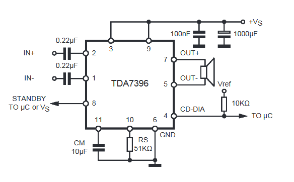
For the leg 8, we feed + vs, and I do not apply anything on the foot. Consequently, the scheme will take this kind:

VS is the supply voltage. It can be from 8 to 18 volts. "In +" and "In-" - here we give a weak beep. To 5 and 7 legs cling the speaker. Sadim's sixth leg on minus.
Here is my assembly mounted installation

Capacitors at the power supply of 100 NF and 1000MKF I did not use, since I have a clean voltage from the power supply.
Rasked the speaker with such parameters:

As you can see, the resistance of the coil 4 Ohm. The frequency band indicates that it is a subwoofer type.
And so I look like a sub in a self-mounted building:

I tried to shoot a video, but the sound on the video I removes very badly. But still, I can say that from the phone at the middle power it has already fallen so that the ears wrapped around, although the consumption of the entire scheme in the working form was only about 10 watts (multiply 14.3 by 0.73). In this example, I took the tension as in the car, that is, 14.4 volts, which is fully fitted into our working range from 8 and to 18 volts.

If you do not have a powerful power source, it can be collected according to this scheme.
Do not dwell precisely on this chip. These TDA chips, as I said, there are many species. Some of them enhance the stereo signal and can issue sound at once on 4 speakers, as is done in car radio. So do not be lazy to ride on the Internet and find a suitable thought. After completing the assembly, let the neighbors check your amplifier, twisting the volume knob to the entire balalaica and leaning the powerful speaker to the wall).
But in the article I collected the amplifier on the TDA2030A chip

It turned out very well, since TDA2030A has better characteristics than TDA7396
Also, I will also apply for a variety of still scheme from the subscriber who has an amplifier on TDA 1557Q for more than 10 years in a row:

Amplifiers on Aliexpress
On Ali, I also found a whale sets on TDA. For example, this stereo amplifier of 15 watts per canal at a price of $ 1. This power is enough to sweat under favorite tracks in the room

You can buy.
And here he is immediately ready

And in general, these amplifier modules on AliqPress are very much. Press on this link And choose any favorite amplifier.
 How to pay a domain name
 Domain zone of tokelau islands
 What is domain what problems may be
 Yandex Wordstat: detailed instructions for using the service and grouping operators and a complicated request
 Editing DBF files
 Xenu Link Sleuth - What is this program how to use the Xenu program
 Methods Copy and insert text from keyboard without using mouse