Simple germanium power amplifier. Simple German Power Amplifier Amplifier LC on Germany Transistors
The main feature of the ISSF published below is the use of broadband OOS in it, frequency characteristic Which, in contrast to the OOS of conventional multi-stage UMPs, does not have a deep cut on higher audio frequencies. To implement the linearizing capabilities of broadband OOS, it was decided to abandon multi-stage UMPs and limit the number of its cascades is only extremely necessary. In addition, it was necessary to refuse to use elements that create a delay of the enhanced signal, which made it possible to use the EOS in the frequency spectrum of switching distortion. As a result, using an OOS acting in the range of 40..60 kHz, it was possible to achieve a decrease in the coefficient of nonlinear distortions at a frequency of 20 kHz to 0.05 ... 0.01% when using the operating stage of the output cascade with zero and rest current.
The pre-core voltage amplifier is built on two TRANSISTORS UT1 andVt. 2. Through the C1 capacitor to the transistor baseVt. 1 Enters the input signal, and through resistorsR 3, R 4 - Balancing power supply voltage. For warranty stable work Amplifier capacitance capacitors C1, C6 and C8 should not differ from those indicated on concept More than 50%. In order to protect against random current overloads to the collector circuit of the transistor, the resistor is includedR. 7. Cascade on the transistorVt. 2 provides basic signal strengthening. Resistor chainRL 1 R 12 With the traditional voltoddular through the C8 capacitor, the amplitude of the amplitude of the increased signal is increasing by 10..12%. The synchronization of the functional processes in the shoulders of the amplifier provides C5 condenser.
Turning current amplifier built on complementary pair of transistorsVT 5- VT 8 included in the circuit with a common collector. Interconed by emitters TransistorsVT 3, VT 4 connected bases to the base of transistorsVT 7, VT 8, and collectors - to the databases of transistorsVT 5, VT 6. Using the current circuit feedback A variable resistorR. 13 adjusts the tension on the base of transistorsVT 3, VT 4 and thus ensures the voltage setting on the base of transistorsVT 7, VT 8 0.1..0.2 in the usual and the operation of the terminal transistors in the reinforcement mode with the zero reservoir. It feeds the umzch from the autonomous rectifier without a galvanic connection with the general wire. Due to this, it was possible to reliably protect the speakers from the constant component of the current transistors, without introducing complex relay-transistor protection devices into the amplifier.
Ump is made in a single block with a rectifier. Its dimensions (135x90x60 mm) are determined by the sizes of heat sinks and filter capacitors. The mass of the block is 560. The block is mounted on two plates with dimensions of 130x58, between which heat sinks and filtering capacitors are trampled. On one of the plates, rectifying diodes and output chains are placed, and on the other - all transistors, capacitors and resistors.Most compounds are made by their own conclusions of component elements. ResistorR. 6, CONDENSERS C11 and C12, input chains and load circuit are connected to the shared wire at one point. If the Recommendation of the Monoblock Construction of the UMR will not be used, then the power circuit blocks will be blocked by 0.1 μF capacitors.
To check the parameters of the collected amplifier and the effectiveness used in it, it is recommended to assemble the defect signal selector. Its scheme is shown in the picture. Variable resistors -R 1 and R 8 provide balancing and compensation for the delay of the controlled signal.
Special thanks for pCB and preparation in the description I want to express my friend and just a good person under the nickname Chetlanin..
Power Supply:
Quality can be improved by applying transistors better to the outsters, for example, KT814-815 at 2SC4793-2SA1837, and instead of KT818-819, put KTB688-KTD718 or 2SD718-2SB688. True, these outcomes in the TU247 package, you will need to adjust the board.
In the program at maximum power, the amplifier consumes (not exceeded): 1.6-1.7 A.
The wire resistor is needed when you first turn on, so as not to kill the output transistors if there is some jamb in the installation.
When you first turn on the resistor, if all the way, then you remove it and set the settings, put it, we put the fuse, turn on and listen.
The fuse (or instead of it does not matter) is required for my wiring of the board, since to configure you need to break down + power bus.
PCB (.Lay) and amplifier circuit (.spl) are located.
Nikolay Troshin
Plain germany amplifier Power.
IN lately Increased interest in power amplifiers on Germany transistors. It is believed that the sound of such amplifiers is softer, resembles a "tube sound".
I bring to your attention two simple schemes LF power amplifiers on Germany transistors tested by me some time ago.
Here are used more modern circuit solutionsThan those used in the 70s when Germanium was in the go. This made it possible to obtain decent power when good quality Sound.
The scheme in the figure is lower, is a variant of the LF from my article in the magazine of Radio No. 8 for 1989 (p. 51-55).
output power This amplifier is 30 W with the resistance of the load of acoustic systems 4 Ohm, and approximately 18 W with a load resistance of 8 ohms.
Power supply voltage (U PIT) two-polar ± 25 V;
A few words about the details:
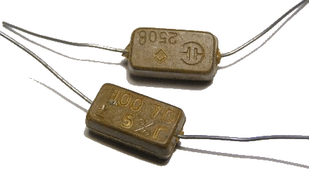
When assembling an amplifier, as capacitors of constant capacity (in addition to electrolytic), it is desirable to use mica capacitors. For example, the type of CSR, such as below in the figure.
MP40A transistors can be replaced with transistors MP21, MP25, MP26. Transistors GT402G - on GT402B; Gt404g - on gt404v;
Output transistors GT806 can be set any letter indexes. Apply lower-frequency transistors of type P210, P216, P217 in this scheme I do not recommend, because at frequencies above 10 kHz, they work badly here (distortions are noticeable), apparently due to lack of current gain at high frequency.
The area of \u200b\u200bradiators on the output transistors should be at least 200 cm2, on the forerunner transistors of at least 10 cm2.
On transistors type GT402, radiators are conveniently made from a copper (brass) or aluminum plate, a thickness of 0.5 mm, 44x26.5 mm.
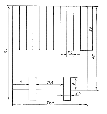
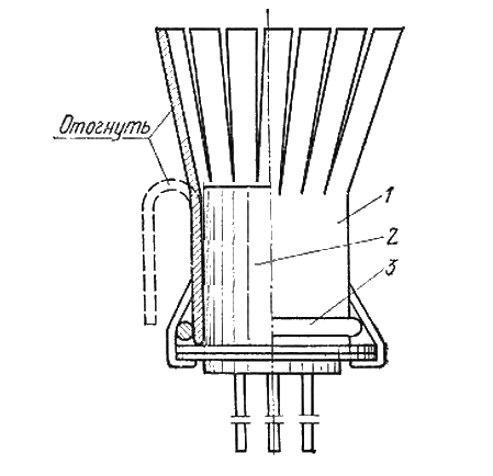
The plate is cut along the lines, then this workpiece is attached to the shape of the tube, using any suitable cylindrical mandrel for this purpose (for example, drill).
After that, the workpiece (1) is tightly worn on the case of the transistor (2) and pressed the spring ring (3), before moving the side fasteners.
The ring is made of steel wire with a diameter of 0.5-1.0 mm. Instead of the ring, you can use the bandage from copper wire.
Now it remains to be cut off the side ears for fastening the radiator per case of the transistor and bend to the desired angle of the capped feathers.
Such radiator can also be made of copper tube, with a diameter of 8mm. Cut a piece of 6 ... 7cm, cut the tube along the entire length on one side. Next, half the length cut the tube into 4 parts and flexing these parts in the form of petals and wear tight on the transistor.
Since the diameter of the transistor housing is 8.2 mm, then due to the slot along the entire length of the tube, it snags tightly on the transistor and will be kept on its body due to spring properties.
Resistors in the emitters of the output cascade - or a wire with a capacity of 5 W, or the type of MLT-2 3 Ohm 3pcs in parallel. We do not advise imported film to use - burn instantly and unnoticed, which leads to the failure of several transistors at once.
Setup:
Setting properly collected from the input elements of the amplifier is reduced to the installation of a trimming cascade of the output cascade of 100mA (conveniently controlled on the emitter resistor 1 Ohm - voltage 100mB).
The VD1 diode is desirable to glue or press the output transistor to the radiator, which contributes to better thermal stabilization. However, if this is not done, the current of resting the output cascade from the cold 100m to the hot 300ma changes, in general, not disastrous.
Important: Before the first inclusion, it is necessary to set a stroke resistor to zero resistance.
After adjustment, it is desirable to drag out of the diagram, measure its real resistance and replace it with a permanent one.
The most deficit item for assembling the amplifier according to the above scheme is the weekend Germany transistors GT806. They were not so easy to purchase them in the bright Soviet time, but now it is probably more difficult. It is much easier to find germanium transistors of types P213-P217, P210.
If you are not able for some reason to purchase GT806 transistors, then you can use another amplifier scheme, where as the output transistors, you can use just the above-mentioned P213-P217, P210.
This scheme is upgrading the first scheme. The output power of this amplifier is 50W with a load resistance of 4 Ohm and 30W at 8-ohm load.
The supply voltage of this amplifier (U Pit) is also two-polar and is ± 27 V;
20Hz operating frequency range ... 20 kHz:
What changes are made to this scheme;
Added two current sources to "voltage amplifier" and another cascade in the "current amplifier".
The use of another cascade of strengthening on fairly high-frequency transistors P605 allowed several unloading transistors GT402-GT404 and stir completely slow P210.
It turned out quite not bad. At the input signal of 20 kHz, and at the output power 50W - on the load of distortions is almost not noticeable (on the oscilloscope screen).
Minimum, little noticeable distortions of the output signal shape with P210 transistors, occur only at frequencies of about 20 kHz with a power of 50 W. At frequencies below 20 kHz and facilities less than 50 W distortion is not noticeable.
In a real musical signal of such capacities, such high frequencies usually does not happen, on this differences in the sound (on hearing) of the amplifier on the GT806 transistors and on the P210 transistors, I did not notice.
However, on GT806 type transistors, if you look at the oscilloscope, the amplifier works even better.
With a load of 8 ohms in this amplifier, it is also possible to use the output transistors P216 ... P217, and even p213 ... p215. In the latter case, the supply voltage of the amplifier will need to be reduced to ± 23V. The output power at the same time, of course, will also fall.
Increasing the same nutrition - leads to an increase in output power, and I think that the amplifier scheme for the second option has such potential (reserve), however, I did not expect the experiments to tempt fate.
Radiators for this amplifier are required by the following - on the weekend transistors of the dispersion area of \u200b\u200bat least 300cm2, on the preimary P605 - not less than 30cm2 and even on GT402, GT404 (with a load resistance of 4 ohms) are also needed.
For transistors GT402-404, you can proceed easier;
Take copper wire (without insulation) with a diameter of 0.5-0.8, wind on a round mandrel (with a diameter of 4-6 mm) wire turn to a turn, bend into the ring the resulting winding (with an inner diameter less than the diameter of the transistor housing), connect the ends soldering And put on the resulting "bagel" on the case of the transistor.
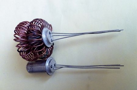
Effectively will turn the wire not on a round, but on a rectangular mandrel, since it increases the area of \u200b\u200bcontacting the wire with the case of the transistor and accordingly increases the efficiency of heat removal.
Also to improve the efficiency of heat removal for the entire amplifier, you can reduce the area of \u200b\u200bradiators and apply to cooling 12V the cooler from the computer, drinking it with a voltage of 7 ... 8B.
P605 transistors can be replaced with P601 ... P609.
Setting up the second amplifier is similar to those described for the first diagram.
A few words by acoustic systems. It is clear that to get good sound They must have appropriate power. Preferably using sound generator - walk on different capacities throughout the frequency range. The sound must be clean, without wheezing and the rat. Especially, as my experience showed, the high-frequency speakers of the S-90 type columns sin.
If anyone has any questions about the design and assembly of amplifiers - ask, if possible I will try to answer.
Good luck to all of you in your work and all the best!
From some of my friends I heard good reviews about the sound of UNG on Germany transistors. And I decided to collect the usual classic scheme on complementary Germany transistors GT703 / 705. On the star - the Cascade of SRPP on 6N30P to obtain possible lower output resistance.
The following scheme:
The VR2 resistor is set to the exit, the VR1 resistor - the rest of the output transistors. Stabilians are needed to prevent the appearance of a voltage dangerous for transistors between the SRPE floors in case of failure of one of the halves of the lamps. The preliminary listening of the layout showed a very good sound, the maximum sinusoidal power is 8 watts, a bar at minus 1 dB from 20 Hz to 80 kHz. Sensitivity - 0.6 volts. The layout played 10 minutes on the maximum volume (how many ears kept) and the radiators of the output transistors did not even heat up to 50 degrees, only the rest current from the initial 40 mA to 100 increased. Power supply: 
For further experiments, the layout was collected in the stereo version. The first tests were made without a seam filter. Adding this item returned the clarity of sound inherent in lamp amplifiers. In general, of course, this is not 2a3, but considering simply carrying the simplicity of the design, the sound is very and very worthy. By a general impression - Typically triode, that is, clean, detailed, accurate, but therefore somewhat low-weather and rustic. It is difficult to say, is the cause of this lamp or transistor part of the scheme, or the scheme itself is to show further experiments - they will certainly continue.
And in conclusion - a pair of pictures like it looks:


Complemented February 21, 2013. Apparently, you can power the output cascade to make on LM7812 and LM7912 installed on the radiator.
 Cellular - what it is on the iPad and what's the difference
 Go to digital television: What to do and how to prepare?
 Social polls work on the Internet
 Savin recorded a video message to the Tyuments
 Menu of Soviet tables What was the name of Thursday in Soviet canteens
 How to make in the "Word" list alphabetically: useful tips
 How to see classmates who retired from friends?