How to make a colorwoman on LEDs with your own hands. Equipment circuit diagram of colorwoman how to make light music on 220 volts lamps
Almost every novice radio amateur, and not only, a desire arose collect a color-duty prefix Or running fire to diversify listening to music in the evening or on holidays. In this article, we will talk about a simple color-music console asserted on lEDswhich is under the power to collect even a novice radio amateur.
1. The principle of action of color-duty consoles.
Work of color-music consoles ( TSP, TSMU or Sdues) Based on the frequency separation of the spectrum of the sound signal, followed by the transmission of it by separate channels low, middle and high Frequencies where each of the channels manages its source of light, the brightness of which is determined by the oscillations of the beep. The final result of the prefix is \u200b\u200bobtaining a color scheme corresponding to the playable musical product.
To obtain a complete range of colors and the maximum number of color shades in color-sheet consoles are used at least three colors:

The separation of the frequency spectrum of the sound signal occurs with LC- and RC filterswhere each filter is configured to its relatively narrow bandwidth and passes through itself only fluctuations in this area of \u200b\u200bthe audio range:
1
. Low Frequency Filter (FNH) passes fluctuations with a frequency up to 300 Hz and the color of its light source is chosen in red;
2
. Middle Frequency Filter (FSH) passes 250 - 2500 Hz and the color of its light source is chosen green or yellow;
3
. Filter of higher frequencies (FVCH) skips from 2500 Hz and above, and the color of its light source is chosen blue.

There are no fundamental rules for selecting a bandwidth or color of lamps, therefore, each radio amateur can use colors based on the features of its color perception, as well as to change the number of channels and the bandwidth.
2. Schematic diagram of the color-music console.
The figure below provides a diagram of a simple four-channel color-duty console assembly collected on LEDs. The prefix consists of an input signal amplifier, four channels and a power supply that ensures power consoles from the AC network.

Sound frequency signal is fed to contacts PC, LK and Common Connector X1, and through resistors R1 and R2 hits a variable resistor R3which is a regulator of the input level. From the average output of the variable resistor R3 Sound signal via condenser C1. and resistor R4. Enters the input of the pre-amplifier collected on the transistors VT1 and VT2.. The use of the amplifier made it possible to use the console with almost any source of the audio signal.
From the output of the amplifier, the sound signal is fed to the upper conclusions of trimmed resistors. R7,R10, R14, R18.which are loading the amplifier and performing the input signal adjustment (adjustment) function separately for each channel, and also set the required brightness of the channel LEDs. From the middle conclusions of trimming resistors, the beep enters the inputs of four channels, each of which operates in its audio band. Schematically, all channels are made equally and differ only by RC filters.
On canal higher R7.
Strip Channel Filter formed by Condenser C2. And only skips the spectrum of the upper sound signal. Low and average frequencies through the filter do not pass, as the resistance of the capacitor for these frequencies is large.

Passing the condenser, the upper frequency signal is detected by a diode VD1. and is fed to the transistor base VT3.. A negative voltage appearing on the basis of the transistor opens it, and a group of blue LEDs HL1 — HL6.included in its collector chain ignite. And the greater the amplitude of the input signal, the stronger the transistor opens, the brighter the LEDs are lit. To limit the maximum current through the LEDs, resistors are enabled R8. and R9. In the absence of these resistors, LEDs may fail.
On canal middle Frequencies The signal is fed from the average rendering of the resistor R10.
Channel strip filter formed by contour C3R11S4.which has a significant resistance for low and higher frequencies, so the transistor base VT4. Only medium-sized fluctuations come. In the collector circuit of the transistor included LEDs HL7 – HL12. green color.
On canal low Frequencies The signal is supplied from the average output of the resistor R18..
Channel filter formed by contour C6R19S7which weakens the signals of the middle and higher frequencies and therefore on the base of the transistor VT6. Only low frequency fluctuations come. Channel load are LEDs HL19 – HL24. of red color.
For a variety of color gamut in a color-duty console added channel yellow colors. Channel filter formed by contour R15C5. And works in the frequency range closer to low frequencies. The input signal to the filter comes from the resistor R14.
Food is powered by a constant voltage 9V.. The power supply unit consoles consists of a transformer T1., diode bridge made on diodes VD5 – VD8., chicketer voltage stabilizer DA1 Type roll5, resistor R22 and two oxide capacitors C8. and C9..
AC voltage straightened by a diode bridge smoothes an oxide capacitor C8. And enters the voltage stabilizer roll5. With output 3 Microcircuits Stabilized Voltage 9V fed into the Cretefront scheme.
To obtain the output voltage 9B between the minus tire of the power supply and the output 2 Microcircuits included resistor R22. The change in the resistance of this resistor is achieved by the desired output voltage at the output. 3 chips.
3. Details.
In the console, any permanent resistors with a capacity of 0.25 - 0.125 watts can be used. The figure below shows the ratings of resistors in which colored stripes are used to indicate the resistance value:

A variable resistor R3 and trimming resistors R7, R10, R14, R18 of any type, just to suit the size of the printed circuit board. In the author's design, a domestic variable SP3-4VM type resistor was used, imported resistors of imported production.

Permanent capacitors can be of any type, and are designed for operating voltage not lower than 16 V.. If it occurs with the acquisition of a C7 capacitor with a capacity of 0.3 μF, it can be made up of two connected capacity of 0.22 μF and 0.1 μF.
Oxide capacitors C1 and C6 must have a working voltage not lower than 10 V, C9 condenser not lower than 16 V, and C8 capacitor not lower than 25 V.

Oxide capacitors C1, C6, C8 and C9 have polarityTherefore, when installing on a master or printed circuit board, it must be considered: the capacitors of Soviet production on the building indicate the positive conclusion, modern domestic and imported capacitors denote a negative conclusion.

VD1 diodes - VD4 any of the d9 series. On the case of the diode case, a color strip is applied, which determines the diode letter.

As a rectifier collected on VD5 diodes - VD8, a finished miniature diode bridge is used, designed for voltage 50V and current of at least 200 mA.

If, instead of the finished bridge, use rectaging diodes, you will have to correctly correct the printed circuit board, or the diode bridge is generally incurred beyond the main board of the console and assemble on a separate small board.
For self-assembly, the diodes bridge are taken with the same parameters as the factory bridge. Any rectifying diodes from the KD105 series, KD106, KD208, KD209, KD221, D229, KD204, KD205, 1N4001 - 1N4007 are suitable. If you use diodes from the KD209 or 1N4001 - 1N4007 series, then the bridge can be collected directly from the printed mounting side directly on the contact sites of the board.
LEDs are ordinary with yellow, red, blue and green glow. Each channel uses 6 pieces:

Transistors VT1 and VT2 from the KT361 series with any letter index.

Transistors VT3, VT4, VT5, VT6 from the KT502 series with any letter index.

Stabilizer voltage type roll5a with any letter index (imported analog 7805). If you use ninety roll8a or roll8g (import analog 7809), then the R22 resistor is not put. Instead of the resistor, a jumper is installed on the board, which connects the average output of the chip with a minus tire, or in the manufacture of the board, this resistor is not provided at all.

To connect the console with a sound source, a jack connector for three contacts is applied. The cable is taken from a computer mouse.

The power transformer is the finished or homemade power of at least 5 W with a voltage on the secondary winding 12 - 15 V with a load current 200 mA.
In addition to the article, look at the first part of the video, where the initial stage of the assembly of the color-music console is shown
On this, the first part ends.
If you are seduced make a colorwoman on LEDs, then pick the items and be sure to check the health of diodes and transistors, for example,. And in the final assembly and configuration of the color-music console.
Good luck!
Literature:
1. I. Andrianov "Consoles to radio receivers".
2. Radio 1990 №8, B. Sergeev "Simple color-music consoles".
3. Operation on the "Start" radio constructor.
The inexhaustible potential of LEDs once again revealed in the design of new and modernization of the existing color-music consoles. 30 years ago, a colorwoman was considered a peak of fashion, collected from multi-colored light bulbs by 220 volts connected to a cassette tape recorder. Now the situation has changed and the tape recorder function now performs any multimedia device, and instead of incandescent lamps, ultra-light LEDs or LED tapes are installed.
The advantages of the LEDs in front of the light bulbs in the color-duty consoles are indisputable:
- wide color gamut and more rich light;
- various versions (discrete elements, modules, RGB ribbons, ruler);
- high response speed;
- low power consumption.
How to make a color music using a simple electronic circuit and force the LEDs flash from the sound frequency source? What options for converting the audio signal exist? These and other issues will consider specific examples.
The simplest scheme with one LED
To begin with, it should be understood with a simple colorwoman circuit collected on one bipolar transistor, a resistor and the LED. Power on it can be served from a DC source with voltage from 6 to 12 volts. This colorwoman works on one transistor on the principle of an amplifying cascade with a common emitter. The perturbing effect in the form of a signal with a changing frequency and the amplitude enters the database VT1. As soon as the amplitude of oscillations exceeds some threshold, the transistor opens and the LED flashes.
The disadvantage of this simple scheme is that the pace of flashing the LED is completely dependent on the sound signal level. In other words, a full color-colored effect will be observed only at one volume level. Reducing the volume will lead to rare winking, and an increase - to almost constant luminescence.
Scheme with monochrome LED ribbon
The simplest color music on the transistor can be assembled using LED tape in the load. To do this, it is necessary to increase the supply voltage to 12V, select the transistor with the highest current current current in excess of the load current and recalculate the resistor's denomination. Such a simple color music from the LED tape is perfect for novice radio amateurs for assembling with their own hands even at home.
Simple three-channel scheme
Get rid of the shortcomings of the previous scheme allows a three-channel sound converter. The simplest colorwoman circuit with the separation of the audio range into three parts is shown in the figure.  It feeds on a constant voltage of 9V and can light one or two LEDs in each channel. The scheme of three independent amplifying cascades collected on KT315 transistors (CT3102), in which the different color LEDs are included. As an element for pre-amplification, you can use a small low-type network transformer.
The input signal is supplied to the secondary winding of the transformer, which performs two functions: galvanically unlock two devices and enhances the sound from linear output. Next, the signal enters three parallel filters collected on the basis of RC chains. Each of them works in a certain frequency band, which depends on the ratings of resistors and capacitors. The low-frequency filter passes sound fluctuations with a frequency of up to 300 Hz, as evidenced by the flashing of the Red LED. A sound in the range of 300-6000 Hz is passed through the average frequency filter, which is manifested in the flicker of the blue LED. The high-frequency filter passes a signal whose frequency is greater than 6000 Hz, which corresponds to the green LED. Each filter is equipped with a trimming resistor. With their help, you can specify a uniform glow of all LEDs, regardless of the musical genre. At the output of the circuit, all three filtered signals are enhanced by transistors.
If the power supply of the circuit is carried out from the low-voltage DC source, the transformer can be safely replaced by a single-circuit transistor amplifier.  First, the galvanic junction loses its practical meaning. Secondly, the transformer loses several times the diagram shown in the figure, by weight, size and cost. The scheme of a simple sound frequency amplifier consists of a CT3102 transistor, two capacitors that cut the constant component, and resistors providing the transistor with a common emitter mode. Using a trim resistor, you can achieve a general gain of a weak input signal.
In the case when it is necessary to increase the signal from the microphone, the electrical microphone is connected to the input of the previous scheme, feeding the potential from the power supply. A diagram of a two-stage pre-amplifier is shown in the figure.  In this case, the trimming resistor stands at the output of the first amplifying cascade, which gives more opportunities to adjust the sensitivity. Condensors C1-C3 skip the useful component and cut off the constant current. For implementation, any electret microphone will suit, for the normal operation of which enough displacement is 1.5V.
Colorwoman with RGB LED Ribbon
The following color-seated console scheme operates from 12 volts and can be installed in the car. It combined the basic functions of the previously considered schematic solutions and is capable of working in color music and lamp mode.
The first mode is achieved at the expense of contactless RGB-ribbon control using a microphone, and the second - due to the simultaneous glow of the red, green and blue LEDs at full power. The selection of the mode is carried out using a switch placed on the board. Now let's stop in detail on how to make a colorwoman, which is perfectly suitable even for installation in a car, and which details will be required for this.
Structural scheme
To understand how this color-chicted console works, first consider its structural scheme. It will help trace the full way to pass the signal.  The source of the electrical signal is a microphone that converts sound oscillations from the phonogram. Because This signal is overly small, it must be enhanced using a transistor or operational amplifier. Then the automatic level controller (ARU) follows, which holds the oscillations of the sound within reasonable limits and prepares it to further process. Filters divide the signal to three components, each of which only works in one frequency range. In the end, it remains only to enhance the prepared current signal, which use transistors operating in key mode.
Schematic scheme
Based on the structural blocks, it is possible to proceed to the consideration of the schematic diagram. Its general view is shown in the figure.  To limit the current consumption and stabilization of the supply voltage, the R12 resistor and the C9 condenser are installed. To set the microphone offset voltage, R1, R2, C1 is installed. Condenser C Fc is selected individually to a specific microphone model in the process of adjustment. It is necessary in order to slightly muffle the signal of the frequency that prevails in the operation of the microphone. Usually reduce the effect of the high-frequency component.
Unstable voltage of the automotive network can affect the work of the colorwoman. Therefore, the self-made electronic devices are most correctly connected through a 12V stabilizer.
Sound oscillations in the microphone are converted to an electrical signal and across C2 come to direct input of the operational amplifier DA1.1. From its output, the signal should be on the operating amplifier Da1.2 input, equipped with a feedback chain. Resistance resistance R5, R6 and R10, R11 Set the gain of DA1.1, DA1.2 equal to 11. OS circuit elements: VD1, VD2, C4, C5, R8, R9 and VT1, together with DA1.2, are part of the ARU. At the time of occurrence of the DA1.2 output of the signal too large amplitude, the VT1 transistor opens and via C4 closes the input signal to the general wire. This leads to an instantaneous reduction in outlet voltage.
Then, the stabilized audible audio frequency current passes through the cutting capacitor C8, after which it is divided into three RC filters: R13, C10 (LC), R14, C11, C12 (SC), R15, C13 (HF). In order for the colorwoman on the LEDs of the shine, it is clear enough to enhance the output current to the appropriate value. For a tape with consumption up to 0,5A, the transistors of the CT817 type transistors or imported BD139 without installation on the radiator are suitable. If the collected light summission does with their own hands implies the load of about 1a, then the transistors will need forced cooling.
In the collectors of each output transistor (parallel to output) there are D6-D8 diodes, whose cathode are combined with each other and are displayed on the SA1 switch (WHITE LIGHT). The second switch of the switch is connected to the shared wire (GND). While SA1 is open, the scheme works in color music mode. When the switch contacts is closed, all the LEDs in the tape are ignited on the full brightness, forming a white stream of light in the amount.
PCB and assembly details
For the manufacture of the printed circuit board, you will need one-sided textolum of 50 size to 90 mm and a ready-made file.Lay that can be downloaded. For clarity, the board is shown by radio elements. Before printing, you must specify its mirror image. The M1 layer shows 3 jumpers placed on the part side.  For the assembly of the colorwoman from the LED tape, you will need accessible and inexpensive components. An electret type microphone is suitable in a protective housing with old audio equipment. The light music is collected on the TL072 chip in the DIP8 case. Capacitors, regardless of type, should have a supply of voltage and be designed for 16V or 25V. If necessary, the design of the board allows you to set output transistors into small radiators. From the edge, the terminal block is placed on 6 positions for power supply, connecting RGB LED tape and switch. The full list of items is given in the table.
  In conclusion, I would like to note that the number of output channels in a homemade color-duty console can be increased by how much it pleases. To do this, you need to split the entire frequency range for a larger number of sectors and recalculate the bandwidth of each RC filter. To the outputs of additional amplifiers, connect intermediate colors LEDs: purple, turquoise, orange. From such an improvement of the colorwoman with their own hands will be only more beautiful.
The following schemes belong to the CXEm.net site
Read the same way
LEDs are used as emitters. The scheme does not require configuration and starts to work immediately after the assembly. To change the brightness of the LEDs, you can pick up the ratings of the resistors. Input chains can be combined to serve a signal from one source. The coil L is any, selected experimentally, can be eliminated quite from the scheme.
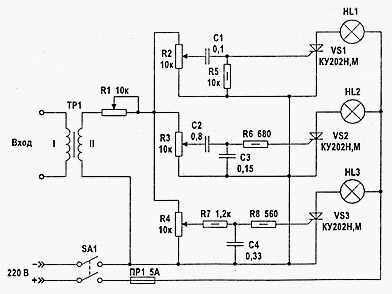
In this variant of the color music scheme, 220 volts lamps are used as a load. The device is assembled on passive elements as frequency filters, thyristors CU202 are used as control triggers. A transformer of any, with a coefficient of 1 to 2 ... 1 to 5.
The tracking scheme has control performed on semiconductor transistors. Transformer T1 has a transformation coefficient 1 to 1. Exemplary resistance of any DC winding - at least 200 ohms. The supply transformer must have at the output of 15-18 volts. Load current at least 0.1 amp.

Structurally, any color-chill (light-music) installation consists of three elements. Control block, power gain block and output optical device.
As an output optical device, it is possible to use garlands, it is possible to arrange it as a screen (classic option) or apply the electrical lamps of the directional action - spotlights, headlights.
That is, any means allowing you to create a certain set of colorful lighting effects.
Power amplification unit is an amplifier (amplifiers) on transistors with thyristor output controls. From the parameters of the elements used in it, the voltage and power of the light sources of the output optical device depends.
The control unit controls the intensity of light, and alternate colors. In complex special installations intended for the design of the scene during various types of shows - circus, theatrical and pop views, this unit is manually controlled.
Accordingly, the participation of at least one is required, and the maximum - groups of illuminator operators.
If the control unit is controlled directly to the music, it works for any given program, the color-chicing unit is considered automatic.
It is this kind of "colorwoman" usually collect novice designers with their own hands - radio amateurs, over the past 50 years.
The simplest (and popular) scheme of "colorwomen" on thyristors ku202n.

This is the most simple and perhaps the most popular color-chicted console scheme, on thyristors.
Thirty years ago, I first saw near a full-fledged, working "light summutor". She was collected by my classmate, with the help of an older brother. It was this scheme. Undoubted advantage is simplicity, with a sufficiently obvious separation of modes of operation of all three channels. The lamps are not blinking at the same time, the red low-frequency channel is stably blinking in rhythm with shock, medium - green responds in the range of human voice, high-frequency blue reacts to the rest of the delicate - ringing and signer.
The lack of one is a preliminary power amplifier for 1-2 watts. My comrade accounted for almost "to the complete" cut off his "electronics" in order to achieve sufficiently stable operation of the device. As an input transformer, a lowering tr-p from a radio station was used. Instead, you can use any small-sized lowering network trance. For example, from 220 to 12 volts. Just connect it, you need to vice versa - low-voltage winding on the amplifier input. Resistors any, power from 0.5 watts. Condenters are also any, instead of thyristors KU202N, you can take CU202M.
Circuit "Currents" on CU202N thyristors, with active frequency filters and current amplifier.

The scheme is designed to work from linear audio output (the brightness of the lamp does not depend on the volume level).
Consider in more detail how it works.
The beep is fed from a linear output to the primary winding of the separation transformer. From the secondary winding of the transformer, the signal comes to active filters, through resistors R1, R2, R3 regulating its level.
Separate adjustment is necessary to configure the quality of the device, by aligning the brightness level, each of the three channels.

Using the filters, the signals are separated by frequency - to three channels. On the first channel there is a low-frequency component of the signal - the filter cuts all the frequencies above 800 Hz. The filter setting is performed using a R9 trimmed resistor. Capacitor rates C2 and C4 in the diagram are indicated - 1 μF, but as practice has shown - their capacity should be increased at least to 5 microf.

The second channel filter is configured to the middle frequency - from about 500, to 2000 Hz. The filter setting is performed using a R15 trim resistor. Capacitor rates C5 and C7 in the circuit are indicated - 0.015 μF, but their capacity should be increased, to 0.33 - 0.47 μF.

According to the third, the high-frequency channel passes all that above 1500 (up to 5000) Hz. The filter setting is performed using a R22 trim resistor. Capacitor rates C8 and C10 in the circuit are indicated - 1000 PF, but their capacity should be increased to 0.01 μF.

Further, each channel signals are separately detected (Germany transistors of the D9 series) are used), enhanced and fed to the terminal cascade.
The terminal cascade is performed on powerful transistors, or on thyristors. In this case, these are thyristors ku202n.

Next, it is an optical device, a design and an external of which depends on the fantasy of the constructor, and the filling (lamps, LEDs) is from the operating voltage and the maximum power of the output cascade.
In our case, these are incandescent bulbs 220V, 60W (if you set thyristors on the radiators - up to 10 pcs per channel).
The procedure for assembling the scheme.
On the details of the console.
CT315 transistors can be replaced by other silicon N-P-N transistors with a static gain of at least 50. Permanent resistors - MLT-0.5, variables and trimmed - SP-1, SPO-0.5. Capacitors - any type.
Transformer T1 with a 1: 1 coefficient, so you can use any with a suitable number of turns. With an independent manufacture, you can use the Magnetic Line of the C10X10, and the windings are coated with a wire PEV-1 0.1-0.15 to 150-300 turns each.
The diode bridge for the nutrition of thyristors (220V) is chosen based on the suspected load power, at least 2a. If the number of lamps per channel to increase - consumed the current consumed.
To power the transistors (12V), you can use any stable power supply unit for a working current to a minimum - 250 mA (and better - more).
First, each channel of the colorwoman is collected separately on the dumping board.
Moreover, the assembly starts from the output cascade. Having collected the output stage check its performance by applying a sufficient level on its input.
If this cascade is working normally, they collect an active filter. Next - check again the performance of what happened.
As a result, after testing, we have a real-working channel.
Similarly, it is necessary to collect and rebuild all three channels. Such a bore guarantees the unconditional performance of the device after the "finishing" assembly on the circuit board, if the work is carried out without errors and using the "tested" details.
Possible printing option (for textolite with one-sided foil). If you use a more overall capacitor in the lowest frequency channel, the distances between the holes and the conductors will have to be changed. The use of textolite with bilateral foils can be a more technological option - it will help to get rid of jumper hinged wires.

Use of any materials of this page, allowed if there is a link to the site
 Privazer program for cleaning the computer for the benefit of performance and in order to notice tracks of activity
 How to change Adobe Reader in Russian How to put Russian in Adobe Reader
 Professional video shooting on smartphone
 Free SAMSUNG KIES drivers in Russian for computer with OS Microsoft Windows
 How to create a channel on YouTube and make money - step by step instructions
 How to completely remove Yandex browser
 Free Update Anti-Virus 360 Total Security do not put vulnerabilities