Why the capacitor does not miss a constant current. Why does the capacitor misses the constant current, but it skips the variable? How the condenser is arranged
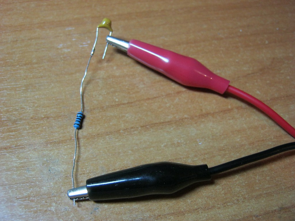
Constant voltage and exhibit voltage at 12 volts on its crocodiles. Light bulb also take 12 volts. Now there is a capacitor between one puzzle of the power supply and light bulbs:
Not, not lit.
But if you directly do, then it burns:

From here, the conclusion suggests: d.C. Through the condenser does not flow!
To be honest, then at the most initial moment of supplying voltage, the current is still flowing at a split second. It all depends on the capacitance of the condenser.
Condenser in alternating current circuit
So, to find out whether an alternating current flows through the capacitor, we need an alternator of the AC. I think this frequency generator will completely come down:

Since the Chinese generator is very weak, then we will use a simple per 100 ohm instead of a light bulb. We will also take a capacitor with a capacity of 1 microfrades:

Sinking somehow like this and give a signal from the frequency generator:
Next for business is taken. What is the oscilloscope and what is eating it, read here. We will use two channels at once. Two signals will be displayed on one screen. Here on the screen there are already visible tips from the network of 220 volts. Do not pay attention.

We will feed alternating voltage and watch signals, as Professional Electrical Covers say, at the input and output. At the same time.
All this will look something like this:

So, if we have the frequency zero, then this means a constant current. Permanent current, as we have already seen, the condenser does not miss. It seems to have figured out. But what will happen if sinusoid with a frequency of 100 hertz?
On the oscilloscope display, I brought parameters such as the frequency of the signal and its amplitude: F. - This is the frequency, MA. - amplitude (these parameters marked the white arrow). The first channel is marked with red, and the second channel is yellow, for the convenience of perception.

Red sinusoid shows a signal that gives us a Chinese frequency generator. Yellow sinusoid is what we already get on the load. In our case, the load is a resistor. Well, that's all.
As you see on an oscillogram above, from the generator, I serve a sinusoidal signal with a frequency of 100 hertz and 2 volt amplitude. On the resistor, we already see a signal with the same frequency (yellow signal), but its amplitude is some 136 Milvololt. Yes, the signal turned out to be some kind of "shaggy". This is due to the so-called "". Noise is a signal with a small amplitude and erratic change in voltage. It can be caused by the radio elements themselves, and it may be interference that are caught from the surrounding space. For example, very good "noise" resistor. So the "Lochness" of the signal is the sum of sinusoids and noise.
The amplitude of the yellow signal has become less, and the graph of the yellow signal is shifted to the left, that is, ahead of the red signal, or scientific language, appears shift phases. It is the phase that is ahead, and not the signal itself.If the signal itself was ahead, then we would then work out that the signal on the resistor would appear in time before than the signal filed on it through the capacitor. It would have happened some kind of movement in time :-), that of course, it is impossible.
Shift phases - this is The difference between the initial phases of the two measured values. In this case, the voltage. In order to perform a phase shift measurement, a condition should be that these signals one and the same frequency. The amplitude may be any. Below in the figure shows this very phase shift or, as it is also called, phase difference:

Let's increase the frequency on the generator to 500 Hertz

On the resistor already received 560 Millivolt. Phase shift decreases.
Increase the frequency to 1 kilohertz

At the exit we already have 1 volt.
We put the frequency of 5 kilohertz

Amplitude 1.84 Volta and phase shift clearly becomes less
We increase to 10 kilohertz

The amplitude is almost the same as at the entrance. Shift phases is less noticeable.
We put 100 kilohertz:

The phase shift is almost no. The amplitude is almost the same as at the entrance, that is, 2 volts.
From here we make deep conclusions:
Than more frequencyMoreover, the condenser has a variable current. Phase shift decreases with increasing frequency almost to zero. On infinite low frequencies Its value is 90 degrees orπ / 2. .
If you build a string of graphics, then it turns out something like that:

Vertical I postponed the tension, horizontally - frequency.
So, we learned that the resistance of the capacitor depends on the frequency. But is it only from frequency? Let's take a capacitor with a capacity of 0.1 microfarads, that is, a denomination is 10 times less than the previous one and again run through the same frequencies.
We look and analyze the values:


Carefully compare the amplitude values \u200b\u200bof the yellow signal at the same frequency, but with different capacitor rates. For example, at a frequency of 100 hertz and the value of the capacitor in 1 μF, the amplitude of the yellow signal was 136 Milvololt, and on the same frequency of the amplitude of the yellow signal, but with a capacitor of 0.1 μF, 101 Milvololt was already 101 (in reality, even less due to interference ). At the frequency of 500 Hertz - 560 Milvololt and 106 Milqualt, respectively, at a frequency of 1 kilohertz - 1 volt and 136 Milvololt and so on.
Hence the output suggests itself: with a decrease in the rating of the condenser, its resistance becomes more.
With the help of physico-mathematical transformations, physics and mathematics brought the formula to calculate the resistance of the capacitor. Please love and respect:

where, X S. - This is the resistance of the condenser, Ohm
P -constant and equals approximately 3.14
F. - Frequency, measured in hertz
FROM - Capacity, measured in the Farades
So, put the frequency in this formula in zero hertz. The frequency at zero hertz is a constant current. What happens? 1/0 \u003d infinity or very large resistance. In short, the circuit break.
Conclusion
Run forward, I can say that in this experience We got (FVCH). Using a simple capacitor and resistor, applying somewhere in sound equipment such a filter on a speaker, in the dynamics we will only hear the squeaky high tones. But the frequency of the bass just muffled such a filter. The dependence of the resistance of the capacitor from the frequency is very widely used in electronics, especially in various filters, where it is necessary to pay off one frequency and skip the other.
It was told about electrolytic capacitors. Basically, they are used in DC circuits, as filtering containers in rectifiers. Also, without them, do not do in the unleashing supply chains of transistor cascades, stabilizers and transistor filters. At the same time, as mentioned in the article, they do not miss direct current, but they do not want to work on the variable.
For alternating current circuits, there are non-polar capacitors, and, the set of their types says that the working conditions are very diverse. In cases where the high stability of parameters is required, and the frequency is high enough, air and ceramic capacitors are used.
Increased requirements are imposed on the parameters of such capacitors. First of all, it is high accuracy (small tolerance), as well as a small temperature factor of tank. As a rule, such capacitors are asleep in oscillatory contours of the receiving and transmitting radio equipment.
If the frequency is small, for example, the frequency of the lighting network or the frequency of the sound band, then it is quite possible to use paper and metal-making capacitors.
Capacitors with a paper dielectric have a thin metal foil, most often aluminum. The thickness of the plates oscillates within 5 ... 10 mkm, which depends on the condenser design. A dielectric with capacitor paper impregnated with insulating composition is nested between the plates.
In order to increase the working voltage of the capacitor, the paper may be laid in several layers. All this package twists like a carpet path, and is placed in a circular or rectangular housing. At the same time, of course, conclusions are made from the plates, and the case of such a condenser is not connected with anything.
Paper capacitors are used in low-frequency circuits at large operating stresses and significant currents. One of these very common applications is the inclusion three-phase engine in a single-phase network.
In the metal-handing capacitors, the role of the edge is sprayed in a vacuum on condenser paper the thinnest layer of metal, all the same aluminum. The design of the capacitors is the same as paper, however, the dimensions are much less. The scope of both types is approximately the same: permanent, pulsating and alternating circuits.
The design of paper and metal-making capacitors, except for the container, provides significant inductance to these capacitors. This leads to the fact that on some frequency, the paper capacitor turns into a resonant oscillating circuit. Therefore, such capacitors are used only at frequencies of no more than 1 MHz. Figure 1 shows paper and metal worker capacitors produced in the USSR.
Picture 1.
Vintage metal worker capacitors had a self-healing property after breakdown. These were capacitors of types of MBG and IBGC, but now they were replaced by condensers with a ceramic or organic dielectric type K10 or K73.
In some cases, for example, in analog storage devices, or otherwise, special requirements are presented to condensers, in particular, a small leakage current. Then condensers come to the rescue, the dielectrics of which are made of high resistance materials. First of all, these are fluoroplastic, polystyrene and polypropylene capacitors. Several smaller insulation resistance in saliva, ceramic and polycarbonate capacitors.
These same capacitors are used in pulse schemesWhen high stability is required. First of all, for the formation of various time delays, pulses of a certain duration, as well as to set the operating frequencies of various generators.
In order for the temporary scheme parameters to be even more stable, in some cases it is recommended to use capacitors with an increased operating voltage: there is nothing bad in that in the 12V voltage scheme to install a condenser with an operating voltage of 400 or even 630V. Places such a condenser will take, of course, more, but also the stability of the whole scheme as a whole will also increase.

The electrical capacitance of capacitors is measured in Farades F (F), but this value is very large. Suffice it to say that the capacity of the globe does not exceed 1f. In any case, it is so written in the textbooks of physics. 1 Faraday is a container at which when charging Q in 1 pendant, the potential difference (voltage) on the condenser plates is 1B.
From just said it follows that Faraday the value is very big, so in practice more often use smaller units: microfrarad (ICF, μF), nanoforads (NF, NF) and pycofarades (PF, PF). These values \u200b\u200bare obtained by using dolle and multiple consoles that are shown in the table in Figure 2.

Figure 2.
Modern details are becoming less and less, so it is not always possible to apply complete labeling on them, more and more often use various systems. conventions. All these systems in the form of tables and explanations to them can be found on the Internet. On capacitors intended for SMD installation, no designation is most often not set. Their parameters can be found on the package.
In order to find out how the capacitors in the alternating current circuits behave, it is proposed to do several simple experiments. At the same time, some special requirements for capacitors are not presented. It is quite suitable for the most ordinary paper or metal-making capacitors.
Condenters conduct alternating current
To make sure that it is enough to assemble the simple scheme shown in Figure 3.
Figure 3.
You must first turn on the lamp through C1 and C2 capacitors connected in parallel. The lamp will glow, but not very bright. If you now add another C3 condenser, then the glow of the lamp will increase noticeably, which indicates that the capacitors have resistance to the passage of AC. Moreover, a parallel connection, i.e. Increase capacity, this resistance reduces.
Hence the output: the greater the container, the smaller the resistance of the condenser under the passage of the AC. This resistance is called capacitive and in the formulas is indicated as XC. An XC also depends on the current frequency than it is higher, the less XC. This will be said somewhat later.
Another experience can be done using the electricity meter, having previously disabled all the consumers. To do this, connect parallel to the three condenser over the 1MKF and simply turn them on into the outlet. Of course, it is necessary to be extremely careful, or even solder a standard plug for condensers. Work voltage capacitors should be at least 400V.
After this connection, it is enough to just watch the counter to make sure that it stands still, although according to the calculations, such a capacitor is equivalent to the resistance of the incandescent lamp with a capacity of about 50W. Asks why the counter does not turn? This will also be told in the next article.
The standard capacitor with the circuit designation "C" refers to the category of the most common radio components operating in chains of both AC and DC. In the first case, it is used as an element of blocking and capacitive load, and in the second - as a filtering link, rectifier chains with a pulsating current. The condenser in the AC circuit looks like this is shown in the figure below.
In contrast to another common radio component, called a resistor, the capacitor in the AC circuit contributes to it the reactive component, which leads to the formation of the phase shift between the applied EMF and caused by it. We will get acquainted with the fact that such a reactive component and spectacular resistance is in more detail.
Inclusion in the sinusoidal EDC chain
Types of inclusions
Condenser in DC circuits (without a variable component) work, as is known, can not.
Note! This statement does not apply to smoothing filters, where the pulsing current flows, as well as special blocking circuits.
A completely different picture is observed if we consider the inclusion of this item in the AC circuit in which it begins to behave more actively and can immediately perform several functions. In this case, the condenser can be used for the following purposes:
- To block a constant component, always present in any electronic circuit;
- In order to create resistance on the path of distribution of high-frequency (HF) components of the processed signal;
- As a capacitive loading element asking frequency characteristics schemes;
- As an element of oscillatory contours and special filters (LC and HF).
Of all the listed it is immediately clear that in the overwhelming majority of cases, the capacitor in the AC circuit is used as a frequency-dependent element capable of providing a certain effect on the signals flowing through it.
The simplest type of inclusion
The processes occurring in such an inclusion are shown below the figure.

They can be described by the introduction of the concept of harmonic (sinusoidal) EMF expressed asU. = Uo. cos. ω t.and look like this:
- At the increase of the variable EMF, the condenser is charged by it electric shock I, maximum at the initial moment of time. As the tank charge, the charging current is gradually decreasing and completely reset at the moment when the EMF reaches its maximum;
Important! Such a multi-directional change in current and voltage leads to the formation between them characteristic of this phase shift element 90 degrees.
- On this, the first quarter of periodic oscillation ends;
- Further, the sinusoidal EMF gradually decreases, as a result of which the condenser begins to discharge, and at this time the current increases in the amplitude of the current. At the same time, it is observed the same lag in the phase, which was in the first quarter of the period;
- Upon completion of this stage, the condenser is completely discharged (at the same time, the EMF is zero), and the current in the chain reaches the maximum;
- As the reverse (discharge) current increases, the capacity is recharged, as a result of which the current is gradually decreasing to zero, and EMF reaches its peak value (that is, the entire process returns to the starting point).
Further, all the processes described are repeated with the frequency of the external EDS frequency. The phase shift between the current and the EMF can be considered as a certain resistance to the voltage change on the condenser (behind the current oscillations).
Capacitance
Concept of capacity
When studying the processes occurring in chains with a capacitor connected in them, it was found that the charge time and discharge for various samples of this element is significantly different from the other. Based on this fact, the concept of container was introduced, determined as the ability of the capacitor to accumulate charge under the influence of a given voltage:
After that, the change in charge on its plates can be represented as:
But sinceQ.= Cu., then we get simple calculations:
I \u003d cxdu / dt \u003d ω c uo cos ω t \u003d io sin (ω t + 90),
that is, the current flows through the capacitor in such a way that it begins to be ahead of the phase voltage 90 degrees. The same result is obtained using other mathematical approaches to this electrical process.
Vector view
For greater clarity in electrical engineering, a vector representation of the processes considered is used, and for a quantitative assessment of the deceleration of the reaction, the concept of capacitive resistance is introduced (see the photo below).

The vector diagram also shows that the current in the condenser circuit is ahead of the phase of a voltage of 90 degrees.
Additional Information. When studying "behavior", the coils in the sinusoidal current circuit was found that he was in the contrary, behind the phase from the voltage.
And in that, and in another case, there is a distinction in the phase characteristics of the processes, indicating the reactive nature of the load in the chain of the EDC variable.
Moisy of attention is difficult to describe differential calculations, for the representation of the resistance of the capacitive load, we obtain:
It follows from it that the resistance created by the capacitor is inversely proportional to the frequency of the variable signal and the container of the element installed in the chain. This dependence makes it possible to build on the basis of a capacitor such frequency-dependent schemes as:
- Integrating and differentiating chains (together with a passive resistor);
- LF and RF filter elements;
- Jet chains used to improve the load characteristics of power equipment;
- Resonant contours of sequential and parallel type.
In the first case, by means of containers, it is possible to arbitrarily change the shape of rectangular pulses, increasing their duration (integration) or reducing it (differentiation).
Filtering chains and resonant contours are widely used in linear schemes of various classes (amplifiers, converters, generators and similar devices).
Schedule of capacitive resistance
It is proved that the current through the capacitor proceeds only under the influence of a harmoniously changing voltage. Moreover, the current of the current in the chain is determined by the capacity of this element, so that the larger the capacitance of the condenser, the more significant.
But you can trace the opposite dependence, in accordance with which the resistance of the capacitor increases with a decrease in the frequency parameter. As an example, consider the schedule shown in the figure below.

Of the above dependences, the following important conclusions can be made:
- For a current of a permanent value (frequency \u003d 0) Xc is equal to infinity, which means the impossibility of its flowing in it;
- At very high frequencies, the resistance of this element tends to zero;
- Upon other things being equal, it is determined by the capacitance of the condenser installed in the circuit.
Definite interest are the issues of the distribution of electrical energy in the AC circuits with the capacitor included in them.
Work (power) in the capacitive load
Similarly, with inductance, in the study of the "behavior" of the capacitor in the circuits of the EMF variable, it was found that the power consumption in them due to the phase shift U and I is not observed. The latter is explained by the fact that electrical energy at the initial stage of the process (during charge) is intensified between the condenser's plates, and in its second stage - is given back to the source (see the picture below).

As a result, capacitive resistance refers to the category of jet, or weightless, loads. However, this conclusion can be considered purely theoretical, since in real circuits there are always conventional passive elements that have non-reactive, and active or watt resistance. These include:
- Resistances of supply wires;
- Conductivity of dielectric zones in the condenser;
- Scattering on contacts;
- Active resistance of turns of coils and the like.
In this regard, in any real electrical chain there are always loss of active power (its scattering), defined in each case individually.
Special attention should be paid to internal losses associated with leaks through a dielectric and poor insulation state between plates (plates). Let us turn to the following definitions that take into account the real state of affairs. So, the losses associated with the qualitative characteristics of the dielectric are called dielectric. Energy costs attributed to the imperfection between the insulation plates are made classified as losses due to leaks in the condenser element.
At the end of this review, it is interesting to trace over one analogy representing the processes occurring in a condenser chain with an elastic mechanical spring. And, indeed, the spring, like this element, for one part of the periodic oscillation accumulates potential energy, and in the second phase - gives it back in kinetic form. Based on this analogy, the entire pattern of the condenser behavior in chains from the EDC variable can be presented.
Video
To the question why the capacitor does not miss a constant current, but it skips the variable? Posted by the author Sodd15 sodd. The best answer is The current flows only until the capacitor is charging.
In the DC circuit, the capacitor is charged relatively quickly, after which the current decreases and almost stops.
In the AC circuit, the capacitor is charged, then the voltage changes the polarity, it begins to discharge, and then charge in the opposite direction, and so on. - the current flows constantly.
Well, imagine a jar into which you can pour water only as long as it is filled. If the voltage is constant, the bank will be filled and after that the current will stop. And if the voltage is alternating - water in the bank is poured - it turns out - poured, etc.
Answer from Strike[newcomer]
thank you guys for cool information !!!
Answer from Avotara.[guru]
Condenser does not miss the current it can only charge and discharge
At constant current, the capacitor charges 1 time and then it becomes useless in the chain.
On the pulsating current when the voltage increases, it is charging (accumulates electrical energy), and when the voltage from the maximum level begins to decrease it returns the energy to the network stabilizing the voltage.
On alternating current when the voltage increases from 0 to the maximum, the capacitor is charged when it decreases from the maximum to 0 discharged returns to the energy back to the network, when the polarity changes everything happens just but with another polarity.
Answer from Vrown[guru]
The capacitor actually does not miss through itself the current. The condenser first accumulates on its plates of charges - on one plane excess electrons, for another disadvantage - and then gives them, as a result, the electrons run there, and here - from one thing they run away, they run away on the second, then back. That is, the movement of electrons there and here in the external chain is ensured, there is current in it - but not inside the condenser.
How many electrons can take a capacitor occurring at a voltage, in one volt, is called the capacitance of the capacitor, but it is usually measured not in the trillions of electrons, but in the conventional units of the container - the pharands (micropraids, picofarades).
When they say that the current goes through the capacitor, it is just simplification. Everything happens as if there was a current through the capacitor, although in fact the current is only outside the condenser.
If you delve into physics, then the redistribution of energy in the field between the condenser plates is called a shift current, in contrast to the conductivity current, which is the movement of charges, but the displacement current is already the concept of electrodynamics associated with the Maxwell equations, a completely different level of abstraction.
Answer from papilla[guru]
in a purely physical plan: Condenser - there is an omission chain, since its gaskets do not come into contact with each other, between them dielectric. And how do we know dielectrics do not conduct electricity current. Therefore, constant current through it does not go.
although...
The capacitor in the DC circuit can be carried out at the time of its inclusion in the circuit (there is a charge or a condenser reload), at the end of the transient process, the current through the capacitor does not flow, since its plates are separated by a dielectric. In the chain of the AC, it conducts alternating current vibrations by cyclic recharging the capacitor.
and for AC, the condenser is part of the oscillatory circuit. It plays the role of a drive of electrical energy and in combination with the coil, they are well coexist, reducing electrical entrust in magnetic and back at a speed / frequency equal to their own Omega \u003d 1 / SQRT (C * L)
example: such a phenomenon like zipper. I think I heard. Although a bad example, there is a charging there through electrification, because of the friction of atmospheric air about the surface of the Earth. But the breakdown is always as in the condenser only when the so-called punch voltage is reached.
i do not know if it helped you 🙂
Answer from [Email Protected]
[newcomer]
the capacitor operates both in alternating current and in constant, since it is charged on a constant current and can not do that energy anywhere, for this, the chain is connected through the key to the reverse branch, to change polarity to discharge and release the place for the new Portions, nea alternating on the turn, Kandur charges and discharged due to the change of polarities ....
Condenser (Capacitor, CAP) is a small "battery", which quickly charges if there is a voltage around it and quickly discharged, when the voltages are not enough to hold the charge.
The main characteristic of the capacitor is the container. It is indicated by symbol C., The unit of its measurement is Farad. The greater the capacity, the greater the charge can hold the capacitor at a given voltage. Also what more Capacity, Top less Charging speed and discharge.
Typical values \u200b\u200bused in microelectronics: from dozens picophaderad (PF, PF \u003d 0.000000000001 Φ) to tens of microfrades (μF, ICF \u003d 0.000001). The most common types of condensers: ceramic and electrolytic. Ceramic less in size and usually have a capacity of up to 1 μF; Anyway, any of the contacts will be connected to the plus, and what - to minus. Electrolytic capacitors have containers from 100 PF and they are polar: a particular contact must be connected to the plus. The leg corresponding to the plus is done longer.
The capacitor is two plates separated by a dielectric layer. Plates accumulate charge: one positive, the other is negative; Thus, inside the voltage is created. An insulating dielectric does not allow internal tension to turn into an internal current, which would equalize the plates.
Charging and discharge
Consider such a scheme:

While the switch is in position 1, voltage is created on the condenser - it is charging. Charge Q. The plate at a certain point in time is calculated by the formula:

C. - Capacity, e. - exhibitor (constant ≈ 2.71828), t. - Time from the start of charging. The charge on the second plate is always the same exactly the same, but with the opposite sign. If resistor R. Remove, only a slight resistance of the wires will remain (it will become the value R.) And charging will occur very quickly.
Posing a function on the chart, we get such a picture:

As can be seen, the charge is growing not evenly, but back-exponentially. This is due to the fact that as the charge is copied, it creates more and more reverse voltage V C.which "resists" V in.
Ends all the fact that V C. becomes equal to value V in And the current ceases to flow at all. At this moment they say that the capacitor reached the saturation point (Equilibrium). The charge at the same time reaches a maximum.
Remembering the Ohm's Law, we can depict the dependence of the current force in our chain when charging the capacitor.

Now that the system is in equilibrium, we put the switch to position 2.

On the capacitor plates of the charges of opposite signs, they create a voltage - a current appears through the load (LOAD). The current will go in the opposite direction, if compared with the direction of power supply. The discharge will also occur on the contrary: first the charge will be lost quickly, then, with a drop in the voltage created by him, everything is slower and slower. If for Q 0 Denote the charge that was on the condenser initially, then:
These values \u200b\u200bon the chart look as follows:

Again, after a while, the system will come to the state of rest: the entire charge will be lost, the voltage will disappear, the current flows.
If you take advantage of the switch again, everything will start in a circle. Thus, the capacitor does nothing except how the chain opens when the voltage is constantly; And "works" when the voltage changes dramatically. This is his property and defines when and how it is applied in practice.
Application in practice
Among the most common in microelectronics, these templates can be distinguished:
Reserve capacitor (BYPASS CAP) - to reduce the rowan
Filter Condenser (Filter Cap) - for separating the constant and changing components of the voltage, to highlight the signal
Reserve condenser
Many schemes are calculated to obtain a constant, stable nutrition. For example, 5 V. They are supplied to them. But the ideal systems do not exist in the case of a sharp change in the current consumption by the device, for example, when a component turns on, the power source does not have time to "respond" instantly and a short-term stress recession occurs. In addition, in cases where the wire from the power supply to the circuit is quite long, it begins to work as an antenna and also to make unwanted noise into the voltage level.

Usually, the deviation from the ideal voltage does not exceed the thousandth share of the volt and this is absolutely slightly, if we are talking about nutrition, for example, LEDs or an electric motor. But in logical circuits, where switching the logical zero and logical unit is based on changing low voltages, noise noise can be erroneously taken for the signal, which will lead to an incorrect switching, which according to the domino principle will supply the system into an unpredictable state.
To prevent such failures, directly in front of the scheme put a backup condenser

At the moments when the voltage is complete, the capacitor is charged to saturation and becomes a reserve charge. As soon as the voltage level on the line falls, the backup capacitor acts as a quick battery, giving the charge accumulated earlier to fill the space until the situation is normalized. Such assistance is a major source of nutrition, there is a huge number of times every second.
If you argue from another point of view: the capacitor highlights the variable from constant voltage and passing it through itself leads it from the power line to the ground. That is why the backup capacitor is also called "Bypass Capacitor".
As a result, the smoothed voltage looks like this:

Typical capacitors, which is used for these purposes - ceramic, denominations of 10 or 100 NF. Large electrolytic is weakly suitable for this role, because They are slower and will not be able to quickly give their charge under these conditions, where the noise has a high frequency.
In one device, backup capacitors may be present in a variety of places: before each diagram, which is an independent unit. For example, ARDUINO already has backup capacitors that provide stable processor operation, but before powering the connected to it. LCD Screen Must be installed your own.
Filter condenser
The filter capacitor is used to remove the signal from the sensor, which transmits it in the form of a changing voltage. Examples of such sensors are a microphone or active Wi-Fi antenna.
Consider the electrical microphone connection scheme. The electret microphone is the most common and ubiquitous: it is supposed to be mobile phones, in computer accessories, speakerphone systems.

For its work, the microphone requires nutrition. In a state of silence, its resistance is great and is tens of keel. When the sound is affected by it, the shutter of the embedded inside the field transistor opens and the microphone loses internal resistance. The loss and restoration of resistance occurs many times every second and corresponds to the phase of the sound wave.
At the exit, we are interested in tension only in those moments when there is sound. If there were no condenser C., I would always have an additional impact constant pressure Nutrition. C. Blocks this constant component and skips only deviations that correspond to the sound.
An audible sound that we and is interesting is located low-frequency range: 20 Hz - 20 kHz. To highlight the sound signal from the voltage, and not high-frequency noise noise, as C. A slow electrolytic capacitor is used with a denomination of 10 μF. If a fast capacitor would be used, for example, by 10 NF, there would be signals that are not related to sound.
Note that the output signal is supplied as a negative voltage. That is, when connecting the exit from the earth, the current will flow from the ground to the exit. Peak voltage values \u200b\u200bin the case with a microphone are dozens of malelvolt. To turn the voltage back and increase its value, output V out. Usually connected to the operating master.
Compound condenser
If compared with the compound of resistors, the calculation of the final rating of capacitors looks like the contrary.
With a parallel connection, the total capacity is summed:

With a consecutive connection, the final container is calculated by the formula:


If the condenser is only two, then with a sequential connection:
In the particular case of two other capacitors total tank serial connection equal to half of the tank of each.
Limit characteristics
The documentation for each condenser indicates the maximum allowable voltage. Its exceeding can lead to a dielectric breakdown and a condenser explosion. Polarity must be respected for electrolytic capacitors. Otherwise, either the electrolyte either flow, or again there will be an explosion.
 Cellular - what it is on the iPad and what's the difference
 Go to digital television: What to do and how to prepare?
 Social polls work on the Internet
 Savin recorded a video message to the Tyuments
 Menu of Soviet tables What was the name of Thursday in Soviet canteens
 How to make in the "Word" list alphabetically: useful tips
 How to see classmates who retired from friends?