What is active reactive and impedance. Reactive resistance XL and XC. Full chain resistance with sequential compound of active and reactive resistance
So, inductors and capacitors prevent the flow alternating current. Such a variable current resistance is called reactive resistance X and measured in Omah. Reactance It depends on both the value of inductance and capacity and the frequency of the signal.
Inductance coil has inductive VL reactive resistance equal
where F is the frequency in Hertz, A L is the inductance in Henry.
Since ω \u003d 2πf, you can write XL \u003d Ωl. For example, the reactive resistance of the coil with an inductance of 10 mPN, which is supplied to a frequency of 1 kHz, equal to
XL \u003d 2π * 1 * 103 * 10 * 10-3 \u003d 62.8 Ohm.
The reactive resistance of the inductance coil increases with increasing signal frequency (Fig. 4.26).
The capacitor has an XC capacitive resistance equal
where C is a container in the Farades. For example, the condenser reactive resistance with a capacity of 1 μF, which is supplied with a frequency of 10 kHz, equal to

Fig. 4.26. The dependence of inductive rice. 4.27.
resistance from frequency.

Fig. 4.28. Capacitive vector sum (XC)
and inductive (XL) resistance.
Fig. 4.29.
(a) inductance coil connected sequentially with R. resistor
(b) vector representation R, XL and their vector sum z
The condenser reactive resistance decreases with increasing signal frequency (Fig. 4.27).
The resulting chain resistance includes capacitive resistance XC and inductive resistance XL, equal to the vector sum XC and XL. Vectors XC and XL, as seen from fig. 4.28 (b) are in antiphase, i.e. the phase difference between them is 1800. Therefore, the resulting resistance is simply equal to the difference between XC and XL. For example, let xl \u003d 100 ohm, and xc \u003d 70 ohms. Then the resulting reactive resistance x \u003d 100 - 70 \u003d 30 ohms and is inductive as XL is greater than XC.
Impedance
The resulting resistance of the chain containing both active and reactive (inductive or capacitive) resistance is the name of the impedance or the total resistance of the chain.
Impedance Z is a vector of the amount of reactive resistance and active resistance R.
Consider, for example, the circuit shown in Fig. 4.29. It includes an inductive resistance XL connected in series with a resistor R. As can be seen from fig. 4.29 (b), vector XL is ahead of the vector R 90 °. Impedance is equal
If xl \u003d 400 ohms and r \u003d 300 ohms, then z \u003d 500 ohms.
Reactance – electrical resistance A variable current due to the transmission of energy by a magnetic field in inductors or an electric field in capacitors.
Elements possessing reactive resistance are called reactive.
Reactive resistance of inductance coil.
When the flow of alternating current I. In the coil, the magnetic field creates an EDC in its turns, which prevents the change in current.
As the current increases, the EMF is negative and prevents the increase in current, with a decrease - positive and prevents its decrease, in this way the resistance to the change in current throughout the entire period.
As a result of the created opposition, the conclusions of the inductor inductance in the antiphase are formed voltage U., the overwhelming EMF equal to the amplitude and the opposite sign.
When current passes through zero, the amplitude of the EMF reaches the maximum value, which forms the discrepancy in the current time and voltage in 1/4 period.
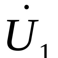
If applied to the conclusions of the inductance coil voltage U., the current can not start instantly because of the opposition of EDC, equal -U.Therefore, the current in inductance will always lag behind the voltage at an angle of 90 °. Shift with lagging current is called positive.
We write the expression instant voltage value u. Based on EMF ( ε
), which is proportional to inductance L. and current changes: u \u003d -ε \u003d L (di / dt).
From here we express a sinusoidal current.
Integral function sIN (T) will be --SS (T)or equal to her function sIN (T-π / 2).
Differential dt. Functions sin (ωt) will come out of the sign of the integral multiplier 1 /ω
.
As a result, we obtain an instant current expression ![]() with a shift from the voltage effect π / 2. (90 °).
with a shift from the voltage effect π / 2. (90 °).
For rms values U. and I. In this case, you can record ![]() .
.
As a result, we have the dependence of the sinusoidal current from the voltage according to the Ohm's law, where in the denominator instead R. expression ωLwhich is reactive resistance:
The reactive resistance of inductors is called inductive.
Condenser reactive resistance.
The electrical current in the capacitor is a part or a set of processes of its charge and discharge - the accumulation and returns of energy by an electric field between its plates.
In the AC circuit, the capacitor will be charged to a certain maximum value until the current change the direction to the opposite. Consequently, at the moments of the amplitude value of the voltage on the condenser, the current in it will be zero. Thus, the voltage on the condenser and the current will always have a discrepancy in time in a quarter of a period.
As a result, the current in the chain will be limited to the voltage drop on the condenser, which creates a reactive resistance to the variable current, a reverse-proportional speed of current change (frequency) and capacitor capacity.
If applied to the condenser voltage U., the current will instantly begin from the maximum value, further decreasing to zero. At this time, the voltage on its conclusions will grow from zero to the maximum. Consequently, the voltage on the plates of the phase capacitor lags behind the current at an angle of 90 °. Such a phase shift is called negative.
The current in the condenser is the derivative of the function of its charge i \u003d dq / dt \u003d c (du / dt).
Derived from sIN (T) will be cOS (T) or equal function sIN (T + π / 2).
Then for sinusoidal voltage u \u003d u amp sin (ωt) We write the expression instant current value as follows:
i \u003d u amp ωcsin (ωt + π / 2).
From here Express the ratio of rms values ![]() .
.
Ohm's law suggests that 1 / Ωc. There is nothing but a reactive resistance for sinusoidal current.
Resistance rendered by the conductor passing on it variable current is called active resistance.
If any consumer does not contain inductance and tanks (incandescent light, heating device), it will also be for AC as active resistance.
The active resistance depends on the frequency of the AC, which is increasing with its increase.
However, many consumers have inductive and capacitive properties when passed through them AC. Such consumers include transformers, chokes, electromagnets, capacitors, various kinds of wires and many others.
When passing through them, it is necessary to consider not only active, but also reactancedue to the presence in the consumer of inductive and capacitive properties of it.
Active resistance Determines the actual part of the impedance:
Where - impedance, is the value of active resistance, the magnitude of the reactive resistance, the imaginary unit.
Active resistance - resistance electrical chain or its site due to irreversible transformations of electrical energy into other types of energy (in thermal energy)
Reactance - electrical resistance due to power transmission by alternating current electrical or magnetic field (and back).
The magnitude of the reactive resistance can be expressed through the values \u200b\u200bof inductive and capacitive resistance:
The magnitude of full reactive resistance
Inductive resistance () It is due to the emergence of self-induction EMF in an electrical chain element.
Capacitance ().
![]() Here - cyclic frequency
Here - cyclic frequency
Impedance Chains with alternating current:
| z \u003d. | √ | R 2 + x 2 | = | √ | R 2 + (X L -X C) 2 |
Ticket number 12.
1. 1) Generator coordination with load -ensuring the required value of the active equivalent load resistance of the generator lamp, R e, with all possible values \u200b\u200bof the input impedance of an antenna feeder, which depends on its wave resistance and the traverse wave coefficient (CBW)
Coordination (in electronics) comes down to right choice Resistances of the generator (source), transmission lines and receiver (load). The ideal coordination (in electronics) between the line and the load can be achieved with the equality of the wave resistance of the line R to the full load resistance ZH \u003d RH + J HN, or with Rh \u003d R and Xh \u003d 0, where Rh-active part of the impedance, Xh is its reactive part. In this case, the transmission line establishes the mode of rubber waves and characterizing their coefficient of the standing wave (CWS) is 1. For line With negligently small losses of electrical energy, coordination and, due to it, the most efficient transmission of energy from the generator in the load is achieved under the condition that the total resistances of the Zr generator and the load of ZH are complex-conjugate, that is, Zr \u003d z * H, or RR \u003d R \u003d R H \u003d XR - XH. In this case, the chain's reactive resistance is zero, and the resonance conditions are observed, which contribute to improving the efficiency of radio engineering systems (improved use frequency ranges, noise immunity increases, frequency distortions of radio signals are reduced, etc.). Assessment of quality Agreement (in electronics) is produced by measuring the reflection coefficient and CWS. Practically coordination (in electronics) is considered optimal if the CWW frequency operating strip does not exceed 1.2-1.3 (in measuring instruments 1.05). In some cases, indirect indicators (in electronics) can serve as a reaction of the parameters of the generator (frequency, power, noise level) to change the load, the presence of electrical breakdowns in the line, heating the individual sections of the line.
With this mode of operation in the receiver, the highest power equal to half the source power. In this case, K.P.D. \u003d 0.5. This mode is used in the measuring circuits, communication devices.
When transferring high power, such as high-voltage power lines, work in a consistent mode is usually unacceptable.
A variable electrical current circuit includes active (containing internal energy sources) and passive elements (energy consumers). Passive elements include resistors and jets.
Types of passive elements
In electrical engineering, two types of resistors are considered: active and reactive resistance. Active - enhanced devices in which the electric current energy is converted to thermal. In physics, it is denoted by the symbol of R. Unit of measurement - OM.
This formula can be used to calculate the instantaneous values \u200b\u200bof current and voltage, maximum or valid.
Jet devices do not dispel energy, but accumulate. These include:
- inductor;
- capacitor.
The reactive resistance is indicated by the symbol of H. Unit of measurement - Ohm.
Inductor
It is a conductor made in the form of a spiral, screw or spirals. Due to high inertia, the device is used in schemes that are used to reduce pulsations in alternating current circuits and oscillatory circuits, to create magnetic field etc. If it has a big length with a small diameter, then the coil is called a solenoid.

To calculate the voltage drop (U.) At the ends of the coil use the formula:
U \u003d -l · di / dt, where:
- L - the inductance of the device, is measured in GN (Henry),
- DI - Changing the current force (measured in amperes) over the time interval DT (measured in seconds).
Attention! With any change in the current in the conductor, self-induction EMPs occurs, which prevents this change.
As a result, the coil arises resistance, which is called inductive.
In the electrical engineering is indicated xL. And calculated by the formula:
where W is an angular frequency, measured in rad / s.
The angular frequency is a characteristic of harmonious oscillation. Associated with frequency F (the number of total oscillations per second). Frequency is measured in oscillations per second (1 / s):
w \u003d 2 · p · f.
If there are several coils in the diagram, then when they are used sequential connection General H.L. for the entire system will be equal to:
XL \u003d XL1 + XL2 + ...
In case of parallel compound:
1 / XL \u003d 1 / XL1 + 1 / XL2 + ...
Ohm law for such a compound has the form:
where UL is a voltage drop.
In addition to inductive, the device has both active R.
Electric impedance in this case is:
Capacitive element
In the conductors and winding of the coil, in addition to inductive and active resistances, there is also a capacitive, which is due to the presence of tank in these devices. In addition to the resistor and coil, a capacitor can be included in the scheme, which consists of two metal plates, between which the dielectric layer is placed.
For your information. The electric current flows due to the fact that the device pass and discharge processes are passing.

With the maximum charge on the instrument plates:
Due to the fact that the resistive device can accumulate energy, it is used in devices that stabilize the voltage in the chain.
The ability to accumulate the charge is characterized by a capacity.
The reactive resistance of the condenser (CC) can be calculated by the formula:
Xc \u003d 1 / (w · c), where:
- w - angular frequency,
- C - capacitance of the condenser.
Capacity measurement unit - F (Faraday).
Considering that the angular frequency is associated with the cyclic frequency, the calculation of the value of the condenser reactive resistance can be performed by the formula:
Xc \u003d 1 / (2 · p · f · c).
If several devices are connected in the circuit, then the totalX.FROM Systems will be equal to:
Xc \u003d xc1 + xc2 + ...
If the connection of objects is parallel, then:
1 / xc \u003d 1 / xc1 + 1 / xc2 + ...
Ohm's law for this case is written as follows:
where Us is the voltage drop on the condenser.
Calculation of chain
With a sequential connectionI. = const. Any point and, according to the Ohm law, it can be calculated by the formula:
where Z is an electric impedance.

The voltage on devices is calculated as follows:
Ur \u003d i · r, ul \u003d i · xl, uc \u003d i · xc.
The vector inductive component of the voltage is directed in the opposite direction from the vector of the capacitive component, so:
consequently, according to calculations:
Attention! To calculate the impedance value, you can use the "triangle of the resistance" in which the hypotenuse is z, and by categories - the values \u200b\u200bof X and R.

If the capacitor and the inductor coil are connected to the chain, then, according to the Pythagore, hypotenuse theorem (Z.) will be equal to:

AsX. = XL – XC., then:

When solving electrical problems, the impedance is often written in the form of a complex number, in which the actual part corresponds to the value of the active component, and the imaginary is reactive. Thus, the expression for impedance in general It has the form:
where I is an imaginary unit.
For online calculation of reactive resistance, you can use the program - a calculator that can be found on the Internet. There are a lot of such services, so you will not be difficult to choose a convenient calculator for you.

Thanks to this Internet service, you can quickly perform the desired calculation.
Video
One of the main problems in the AC voltage network is the presence of reactive power. It is consumed only on thermal losses. The source of reactive energy is the electrical energy drives L and C. I will not very deeply consider this question. I propose to consider this question on the example of simple elements of the chain - inductance and containers.
Inductive element L.
Inductive element (Consider on the example of inductance coil) are the turns of the wires isolated between themselves. When current flow, the coil is magnetized. If you change the polarity of the source, the coil will begin to give stored energy back, trying to maintain the current value in the circuit. Therefore, when it flows through it the variable component, the energy stored during the passing of a positive half-period will not have time to dispel and will prevent the passage of the negative half-period. As a result, the negative half-period will have to pay off the energy stored coil. As a result, the voltage (U) will be ahead of the current (І) for some kind of angle φ. Below is the result of modeling work on L-R Load L \u003d 1 * 10 -3 GN, R \u003d 0.5 Ohm. Ust \u003d 250 V, frequency F \u003d 50 Hz.
φ is the phase difference between U and I.
The reactive resistance is indicated by the letter X, the total z, active R.
For inductance:
![]()
Where ω is cyclic frequency
L - inductance of the coil;
Conclusion: The higher the inductance L or frequency, the greater the coil resistance to the variable current.
Capacitive element
Capacitive element (Consider on the example of the condenser) is a two-streamer with a variable or constant value of the container. Condenser - Drive electrical charges. If you connect it to the power source, it charges. If a source is applied to it with a variable component, it will be charged when the positive half-period is passed through it. When the direction of half aim is to change to a negative value, the capacitor will begin to recharge, that is, the energy that has accumulated in it will begin to counteract the recharge. As a result, we will get tension on the condenser opposite to the source. As a result, it will be discovered by u for some kind of angle φ. Below is the result of modeling work on C-R Load C \u003d 900 * 10 - 6 Fa, R \u003d 0.5 Ohm, Ust \u003d 250 V, frequency F \u003d 50 Hz.
 Figure 2. Operating source on R-C Load
 For capacity:
![]()
Where ω is cyclic frequency
- frequency of the supply voltage, Hz;
C - capacitance of the capacitor;
Conclusion: The higher the capacity of C or frequency, the smaller the resistance to the variable current.
Comparison of the effect of reactive resistance to the active network power
Figures 1 and 2 it can be seen that the phase shift in the figures is not the same. The output - the more in the complete resistance Z will be the effect of X L or X C. The greater will be the difference of phases U and I.
The shear angle between current and voltage is called φ.
Non-phase reactive power:
Three-phase:
![]()
U F, I F - Phase current and voltage
Conclusion: reactive power - does not perform useful effects.
She "distilts" over the network heating cables and increasing losses. In large industrial enterprises, this is especially noticeable due to the availability of electric drives and other major consumers. This issue is very relevant for energy saving and modernization of production. Therefore, on prom. Enterprises are set by compensators of reactive power. They can be of different types and except compensation to perform the role of filters. With the help of compensators, they are trying to maintain the balance of reactive power to minimize its effect on the network and adjust the angle φ to zero.
For it is necessary to maximize the amount (L, C) of the elements in the network.
 Magnetometry in the simplest version The ferrozond consists of a ferromagnetic core and two coils on it
 Effective job search course search
 The main characteristics and parameters of the photodiode
 How to edit PDF (five applications to change PDF files) How to delete individual pages from PDF
 Why the fired program window is long unfolded?
 DXF2TXT - export and translation of the text from AutoCAD to display a dwg traffic point in TXT
 What to do if the mouse cursor disappears