USB formats connectors. Plot micro USB connector. USB-C: Symmetrical Plug
USB interface widely used in modern electronic devicesoh. Almost all mobile devices have a micro or mini-yusb connector. If the connector stopped working, then for repair it is necessary to know the micro-usb pinout. The situation is complicated by the fact that many manufacturers of gadgets perform the split contacts in their own way. Having studied possible options Codes, you can cope with the problem.
Purpose and species
The USB connector has a good set of features. With it, it is possible not only to transmit large amounts of information at high speed, but also provide a device to the device. The new interface quickly replaced old ports on computers, for example, PS / 2. Now all the peripherals connect to the PC precisely using the ports of YUSB.
To date, 3 versions of the USB Connector were created:

Features of the pinout
When talking about a USB connector socket, it is necessary to understand the notation specified in the schemes. Starting with the type of connector - active (type A) or passive (type B). With the help of the active connector, information is exchanged in two directions, and the passive allows you to take it. You should also distinguish between the two forms of the connector:
- F - "Mom".
- M - "Dad".
In this question, everything should be clear without explanation.
USB Standard Connector
 First, several words must be said about the compatibility of the three versions of the interface. Standards 1.1 and 2.0 are completely similar to constructively and differ only in the speed of information transfer. If in the connection one of the parties has the older version, then the work will be carried out at a low speed. At the same time, the OS will display the following message: "This device is able to work faster."
Compatible 3.0 and 2.0 is increasingly complicated. The device or cable of the second version can be connected to a new connector, and reverse compatibility exists only in active Type A. Active connectors It should be noted that the USB interface allows you to submit to the connected gadget voltage in 5 V at a current no more than 0.5 A. For uSB standard 2.0 Sparkout in colors from left to right to see:
- Red - Positive Contact constant voltage in 5 V.
- White - Data-.
- Green - Data +.
- Black - shared wire or "Earth".
The connector circuit is quite simple, and if necessary, it will be fixed. Since the number of contacts increased in version 3.0, then its pinout differs from the previous standard. Thus, the color scheme of contacts is as follows:

MICRO and MINI connectors
 Connectors of this form factor have five contacts, one of which is not always involved. Conductors of green, black, red and white colors perform similar USB 2.0 functions. MINI-USB pinout corresponds to Micro-USB Cobs. In the type connectors, a purple conductor is closed with black, and it is not used in passive.
These connectors appeared thanks to the market to market a large number of small dimensions. Since they are externally similar, users often have doubts about the belonging of the connector to that or another form factor. In addition to some distinctions in the dimensions, the micro-yusb on the back are latches.
Miniaturization of the connector negatively affected reliability. Although mini-USB has a big resource, through a rather short time segment, it begins to hang out, but it does not fall out of the socket. Micro-yusb is a finalized mini-USB version. Thanks to the improved fastening, it turned out to be more reliable. Starting in 2011, this connector has become a single standard for charging all mobile devices.
 However, manufacturers contribute some changes to the scheme. So, pinout micro-USB connector for charging iPhone. It assumes two changes in comparison with the standard. In these devices, red and white wires are connected to black through the resistance of 50 com, and with white - 75 com. There are also differences from the standard and in smartphones Samsung Galaxy. It is closed white and green conductors, and 5 contact is connected to 4 using a resistor with a par value of 200 kΩ.
Knowing the Cocolevka different species USB connectors, you can find and troubleshoot. Most often it is required in a situation where "native" chargerBut the user has a power supply from a smartphone of another manufacturer.
The section is updated daily. Always fresh versions of the best free software For everyday use in the section necessary programs. There are almost everything that is required for everyday work. Start gradually refuse piiira versions in favor of more convenient and functional free analogues. If you still do not use our chat, we just advise you to meet him. There you will find many new friends. In addition, it is the fastest and an effective way Contact project administrators. The antivirus update section continues to work - always topical free updates for Dr Web and Nod. Did not have time to read something? The full content of the running line can be found on this link.
Universal Serial Bus or Abbreviated USB
Universal Serial Bus or Abbreviated USB is actively used in modern digital computer technician. Currently, USB 1.1 and USB 2.0 versions apply. USB 2.0 supports direct and back compatibility with USB 1.1. In other words, the device with USB 2.0 is successfully operating with computers equipped with USB 1.1 and vice versa. All cables and USB 1.1 and USB 2.0 connectors are identical.
USB
USB (Reduction from the English term Universal Serial Bus. - "Universal sequential tire", pronounced Yu-Es-bi) - serial data interface for low-speed and medium-speed peripheral devices in digital computer technician.
Universal Serial Bus (USB) - "Universal Sequential Tire" has its own special designation, Ie of its special graphic symbol.
USB symbol
The USB symbol is four geometric shapes: a large circle, a small circle, a triangle and a square located at the ends of the tree-like flowchart. The USB symbol can be applied on the hardware enclosures, on the connectors and on the device.
USB 2.0 differs from USB 1.1 by introducing Hi-Speed \u200b\u200bmode. USB 2.0 HIGH SPEED has its own logo.

USB 2.0 High Speed \u200b\u200blogo applied on Card Reader

Fig.1. An example of a cable USB. Well visible USB characters on connectors
To connect peripheral devices to the USB bus, a special four-core cable is used, while two veins ( twisted para) In differential enable, used to exchange data, and two others are for powering the peripheral device, see Fig. 2.

Fig.2. USB cable with basic parameter marking
USB allows you to connect peripherals without your own power source (the maximum current consumed by the device by the USB bus supply lines should not exceed 500 mA) see Fig.3.

Fig.3. USB has its own power lines, it allows you to connect peripherals
devices without your own source, for example, an external hard drive
One USB bus controller allows you to connect up to 127 devices on the "Star" topology, including hubs. On one USB bus can be up to 127 devices and up to 5 levels of cascading hubs, not counting the root.
Thanks to its universality, USB gradually displaces such ports as COM and LPT. Fortunately, manufacturers of printers and scanners provide for the operation of their USB devices and provide appropriate connectors. In addition, new non-traditional devices connected to USB appear, such as compact MP3 players. Connecting to USB allows not only to copy music files to such players, but also charges the battery built into them, providing autonomous work Player.
USB cable
The USB cable is four-core in a fever, it consists of 4 copper conductors - 2 power tests and 2 conductor for data transmission in the form of a twisted pair, plus, grounded bar (screen) see Fig.4.

Fig.4. USB cable. Different connectors are clearly visible at the ends of the cable.
This is due to the fact that USB cables are oriented
USB cables are oriented, for this USB cables are supplied with different connectors for connecting "to the device" and "to the host". Implementation possible USB devices Without cable, with built-in tip "to the host". An example of such a device can serve as a flash memory card or USB modem. Perhaps indefinite cable embedding in the device, an example can serve computer mouse See Fig.5. (Standard prohibits it for Full and High Speed \u200b\u200bdevices, but the manufacturers are broken). There are (although it is prohibited by the standard) and passive USB extension cords that have "from the host" and "to the host" connectors.

Fig.5. Independent embedding of a USB cable into a device.
Example, computer mouse is equipped with a built-in USB cable
USB 1.1 and USB 2.0. Connectors, cables and decay
USB connector split circuit (cable and device)

USB connector split circuit (cable and device)
USB signals are transmitted over two wires (twisted pair) shielded four-core cable.
VBUS - Voltage +5 volts Power chains, GND - contact for connecting the "case" of the power chain. The maximum current power consumed by the USB bus supply lines should not exceed 500 mA. The data is transmitted through the contacts D- and D + USB connector. Differential data transfer method is the main for USB.
USB 2.0 standard cable to provide a higher data rate shielded. It is also quadruple, but in the overtake, consists of 4 copper conductors in color isolation. Two power conductors and 2 conductors for data transfer in the form of a twisted pair. Wires are placed in a grounded lamp (screen).
USB cable connectors
Special USB connectors are used for USB cable. USB cable is directed, therefore, for proper connection, USB connectors have a different configuration. There are two types of USB connections: type A (see Fig. 7. and Fig. 8.) and type B (see Fig. 9., Fig.10. And Fig.11).

Fig.7. Normal uSB connector Cable type A.
In accordance with the 1.0 USB specification, the Type A connectors are used to connect "to the host" i.e. Installed on the side of the controller or USB concentrator.

Fig.8. "Corporate" USB connector Type A (with the name of the manufacturer)
In accordance with the 1.0 USB Specification, the Type B connectors are used to connect "to the device" i.e. To connect peripheral devices.

Fig.9. The usual USB connector of the cable type B. This connector is suitable, for example,
To connect printer

Fig.10. The usual USB mini cable connector type B

Fig.11. Connector Micro USB Cable Type B.
In the figure below the USB symbol is clearly seen designation type B
In Fig.12. and Fig.13. Showing USB cables. These USB cables are equipped with a conventional USB Type A Cable Connector and MINI Cable MINI Type B.

Fig.12. USB cables are equipped with a regular cable USB connector
B.

Fig.13. USB cables are equipped with a regular cable USB connector
Type A (in the picture on the left) and USB mini cable connector
Type B (in the picture on the right). Type B is indicated as b.

Fig.14. USB cable equipped with a miniature connector called Micro USB
USB supports "hot" (with power on) Connecting and disabling devices. This has been achieved in the increased length of the undergoing contact of the connector with respect to signal contacts, see Fig. 15. When connecting the USB connector, grounding contacts are first closed, the potentials of the two devices of the device are aligned and the further connection of the signaling conductors does not lead to overvoltages, even if the devices are powered by different phases of the power three-phase network.

Fig.15. Length of grounding contact
The length of the grounding contact (in the figure of contact 4 GND at the top) of the connector is increased relative to the signal (in the picture the contact 3 D + bottom) contacts. The top contact is longer than the bottom. This allows you to connect and disable the power off devices (the so-called "hot" connection and disconnection)
The response parts of the USB connector are located on the peripheral devices connected via USB, see Fig.16. and Fig.17.

Fig.16. Connector for connecting the USB cable connector. Well visible usb symbol

Fig.17. Connector for connecting the USB MINI cable connector type B

Fig.18. Comparison of USB connector sizes.
The usual USB connector of the cable type A (in the picture on the left), the USB MINI connector type B (in the figure in the center) and the USB cable cable connector type B (in the picture on the right). Type B is indicated as B.
USB (Universal Serial Tire) - Transmission Interface uSB data Today, it is common everywhere, it is used in almost all devices of phones, PCs, MFPs, tape recorders and other devices are used both for data transmission and for charging the phone's batteries.
Types of USB connections.
Exists a large number of varieties of types of SUB connectors. All are shown below.
Type A. - active, feeder (computer, host). A type B. - Passive, plug-in device (printer, scanner)
Collecting USB USB pinout.
Pointing USB 2.0.

USB is a serial tire. It uses 4 shielded wires: two for powering (+ 5V & GND) and two for differential data signals (marked as D + and D-).

USB Micro.
USB Micro is used since 2011 in phones, MP3s and in other devices. Micro is a newer MINI connector. It has an advantage in connecting the connectors, the connector is connected tightly with the plug and provides a dense connection.
USB (U-Es-bi, eng. Universal Serial Bus. - "Universal Serial Tire") - serial interface for connecting peripheral devices to computing technology. Received the widest distribution and actually became the main interface for connecting the periphery to the household digital technique.
The interface allows not only to exchange data, but also to provide power to the peripheral device. Network architecture allows you to connect a large number of peripherals even to a device with one USB connector.
The development of USB specifications is made within the framework of the International Non-Profit Organization of USB Implementers Forum (USB-IF), unifying developers and equipment manufacturers with a USB bus. During development, several versions of specifications have been developed. Nevertheless, developers managed to maintain a high degree of compatibility of equipment of different generations.
There are two types of connectors / connections for USB:
- Type A.
- Type B.
Each of the types are divided into three groups:
- Standard
- Micro
Some types of connectors

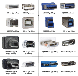
All USB devices have their own version.
The first version of USB connections (1.1). Its characteristic feature is a very small speed at which all information is transmitted with a large delay.
The transfer rate is 12 Mbps. Its main purpose is the application for the interconnection of devices.
Second USB connector version (2.0).
It is characterized by a data rate of 480 Mbps. This corresponds to a speed of 48 MB / s.
The main part of all modern technical devices and devices are adapted to the application of this particular version. It is most popular and known, and therefore everything else is in demand in the electrical engineering market.
True, due to many factors, the current speed of this standard does not have more than 30 - 33 MB / s.
Third USB version (3.0).
This version is characterized by speed transmission rate - 5
Gb / C - what is considered a rather high indicator.
Such speed corresponds 500
MB / s. This is much higher than the speed of the latter generation hard drives (150-170 MB / s).
USB 3.0 connectors for their recognition (sometimes) are specifically marked with blue.

USB power connector
The power to which connected devices with USB connectors is calculated is 2,5 W, as well as 4,5 W (for the third version). Based on this, the USB connectors of all versions requires voltage 5 V. Toka 0,5 A, and for the third version - 0.9 A..
Micro USB 3.0.
Modern external drivesHigh speed, as well as SSD types, are mainly all equipped with such a connector, which is characterized by a high information exchange rate.

USB 3.1 Type-C
- Data transfer rate up to 10 gbps.
- The ability to power from the port of devices with power consumed up to 100W
- Connector Sizes Comparable with Micro-USB
- The symmetry of the connector - it does not have top and bottom, which means there is no key that often leads to damage to both the connectors themselves and the gadgets connected through them
- Via this interface You can power the devices with voltage up to 20 volts
- No longer exist different types Connectors - A and B. At both ends of the cable, there are absolutely identical connectors. As the data and the supply voltage can be transmitted through the same connector in both directions. Depending on the situation, each connector can act as a lead or slave
- We promise that the design of the connector is able to withstand up to 10,000 connections
- It is possible to use this interface to directly connect instead of some other widespread interfaces for quick data exchange.
- The standard is compatible from top to bottom as a conventional USB 3 interface and with his younger brothers. Of course not on the direct, but using the adapter through it it is possible to connect a USB 2.0 disk
UBS connectors are the most common types of connectors that are used to connect different types of digital electronic devices.
We are sure - each in the house has many cables with such connectors, because they are used to connect peripheral devices to a computer: mouse, joysticks, printers, scanners, external hard drives and more.
In contact with
Also when buying a mobile phone, you get connections with it to connect the gadget to the computer and the charger.
The concept of pinout
Sometimes it happens that due to the breakdown of the connector or the cable break stops working charger device for phone Or something connected to the computer. This is for a person who does not own the skill to work as a soldering iron, - an unpleasant surprise And the problem.
But, for a person familiar with the fundamentals of electronics and able to solder, the task is solved simply - a new connector is soldered or the old one turns out, and our favorite devices function again.
However, before reinforcing repair, you need to know topboard USB Connector - The location of the colors in relation to the contacts of the connector. Incorrect decay will lead to the failure of the connected gadgets.
USB Overview Connectors
 USB (universal sequential tire) - The data transfer standard, which was developed in 1994 to organize an interface between a computer and peripheral devices.
Now it is used both for transmitting data between digital devices, and to charge the passive device batteries from the active, so-called "host". An example is the charging of the phone from the computer.
Connectors are divided into three types:
First type - USB 1.1
Was designed one of the first to expand functionality Computer and made it possible to connect additional devices to a computer, including mobile phones for transmitting speech digital form.
Due to the fact that the data transfer rate was low, USB 2.0 came to shift. Currently, USB 1.1 is considered obsolete and practically does not apply.
Second Type - USB 2.0
The most common this moment And widely used. Most electronic devices sold in electronics stores have USB 2.0 connectors, despite the fact that they are no longer quite satisfying the latest transmission rate requirements. In particular, the hard drives can read information at a speed of 3-4 times greater than the speed provided by this type of devices. However, they remain common due to the fact that for the operation of mice, keyboards and other devices, this speed is quite suitable.
Third Type - USB 3.0
It is a new generation of devices, whose transmission rate satisfies the most high-speed hard drive and provides a speed reserve for the future. Connectors this type Specially designated in blue.
All Connectors considered types have constructive differenceswhich can be determined by designation:

Letters F and M in USB marking Connectors mean:
- F (Female) - a slot connector (mother);
- M (MALE) - plug connector (dad).
To connect to portable and mobile devices MINI - USB are developed, and later - Micro - USB.
MINI-AB and Micro-AB connectors are used as transitiones for MINI A and MINI B, Micro-A and Micro-B, Micro-A and Micro-in each other.
Pinout connector
Spacking USB 2.0 connector is:
- Red wire Shipping to contact 1 connector: Food is served + 5V;
- White wire - to contact 2: information (D -);
- Green wire - to contact 3: information (D +);
- Black wire - To contact 4: Common.
Mini and micro USB cables have five wires of different colors and a five-pin connector. The difference of the splitting of such micro connections from the splitting of USB 2.0 connectors lies in the following:
- the decay of the first three contacts is similar to USB 2.0;
- the lilac wire goes to contact 4 - this is id; In connectors A - not used, in connectors B - connected with the case;
- black wire goes to contact 5 - common.
Spacking USB 3.0 connectors It is made as follows:
- the decay of the first 4-contacts is identical to the disintegration of USB 2.0 connector;
- blue wire comes up to contact 5 - transmission of information with a plus sign;
- yellow wire - to contact 6 - transfer information with a minus sign;
- additional case - to contact 7;
- purple wire - to contact 8 - transmission of information with a minus sign;
- orange wire - to contact 9 - transmission of information with a plus sign.
Micro and mini USB for mobile phones
 All modern cell phones Charged through mini and microconnectors from own charger. The plot of mini and microconnectors were considered above.
Now let's talk about why it happens that it seems that the charger in its parameters (voltage and charging current) is suitable, and the connector from your phone is good for it, but the charger is not "native" - \u200b\u200band the charging does not go. Why?
The case is in some differences of the plot of mini and micro-indoor phones inserted into the charger.
For example, such gadgets like HTC, Philips, Samsung, as well as Nokia and LG recognize the charger for their own if 2 and 3 contact in the connector is shortened. By connecting these contacts in the AF connector of the charging device, you can easily use it to charge these types of phones.
Motorola devices "will require" the resistor installations, with a rating of 200 kilomes between 4 and 5 contacts. Without him the device is charging very slowly.
Summarizing the said, you can make a conclusion that when repairing cables to your favorite gadgets, it is important to know the pinout connectors to properly cover the cable wires, and then your electronic "friends" will serve you for a long time.
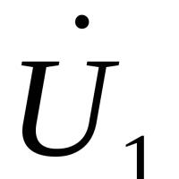 Magnetometry in the simplest version The ferrozond consists of a ferromagnetic core and two coils on it
 Effective job search course search
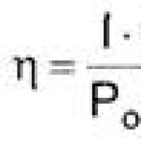 The main characteristics and parameters of the photodiode
 How to edit PDF (five applications to change PDF files) How to delete individual pages from PDF
 Why the fired program window is long unfolded?
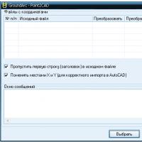 DXF2TXT - export and translation of the text from AutoCAD to display a dwg traffic point in TXT
 What to do if the mouse cursor disappears