USB in a computer where which wire is. Pointing USB in colors. Specifications of each model
In each computer and other similar devices, the most popular is the USB connector. Via yusb wire It became possible to connect more than 100 units of series connected devices. These tires allow you to connect and disconnect any devices even during the operation of the personal computer. Almost all devices can be charged through this connector, so there is no need to apply additional blocks Nutrition. Collecting USB picking helps to accurately determine how the type of devices includes one or another tire.
USB device and assignment
The first ports of this type appeared in the nineties of the last century. After some time, these connectors updated to the USB 2.0 model. The speed of their work has increased more than 40 times. Currently in computers appeared new interface USB 3.0 at a speed, 10 times higher than the previous option.
There are other types of connectors of this type, known as Micro and Mini USB, used in modern phones, smartphones, tablets. Each tire has its own or pinout. It may be necessary if you need to manufacture with your own hands an adapter from one type of connector to another. Knowing all the subtleties of the location of the wires, you can even make charger for mobile phone. However, it should be remembered that in case proper connection The device may be damaged.
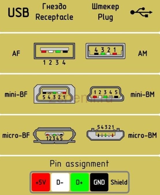
USB 2.0 connector is made in the form of a flat connector in which four contacts are installed. Depending on the purpose, it is marked as AF (BF) and AM (BM), which corresponds to the everyday name "Mom" and "Dad". The mini and micro devices have the same marking. From ordinary tires, they differ in five contacts. USB device 3.0 Externally resembles Model 2.0, with the exception of an inner structure that has nine contacts.
Pickup-decaying connectors USB 2.0 and 3.0
The cutting of the wires in the USB 2.0 model is as follows:

- Red conductor to which the supply is carried out feeding its voltage direct current with + 5V value.
- White explorer used to transfer information data. It is indicated by the label "D-".
- Explorer painted in green color. With it, information is also transmitted. It is marked as "D +".
- Black conductor. On it is made of zero feeding its voltage. It bears the name of its wires and is denoted by its own mark in the form of an inverted T.
The location of the wires in the 3.0 model is performed completely differently. The first four contacting wires fully correspond to the USB 2.0 connector.

The main difference between USB 3.0 lies in the following wires:
- Explorer No. 5 has blue. On it is transferred information with a negative value.
- Explorer No. 6 of yellow color, as well as the previous contact is designed to transmit information that has a positive value.
- Explorer No. 7 is used as an additional grounding.
- Explorer number 8. purple color And Explorer No. 9 orange. They perform the function of receiving data, respectively, with a negative and positive value.
Split-pinboard micro and mini-USB connectors
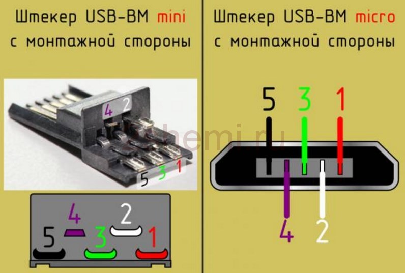
Micro USB connectors are most often used in tablets and smartphones. From standard tires, the Micro USB pinout is characterized by much smaller dimensions and the presence of five contacts. They are marked as Micro-AF (BF) and Micro-AM (Bm), which corresponds to "Mom" and "Pape".

The micro-USB molding is performed in the following order:
- Contact number 1 red. It serves a voltage.
- Contacts Nos. 2 and 3 white and green color are used for transmission.
- Contact number 4 lilac color performs special functions In separate tire models.
- Contact number 5 of black color is zero wire.
Pickup Mini USB Connector for Colors is performed, as well as in micro-yusb connectors.
Connector uSB type It is widely used as an interface connector for domestic appliances, and also actively penetrates the professional sphere. Provides an informational exchange between different modern electronic devices, as well as remote nutrition of low-power terminals.
Interface cables with USB connectors are widely represented on sale. In practice, there is a need for a homemade connecting cord of this species, which is replaced by the failed or simply lost purchased cable, the desired length is provided or the need for an adapter between USB ports of different varieties occurs.
USB connectors features
In total, three main versions of USB interfaces are standardized, each new of them has provided an increase in the speed of information volume and extension of functionality. At the same time, taking into account the expansion of applications, a forms of forks changed.
The ability to connect the cable to the device automatically means compatibility of the connected devices with each other.
USB cord plugs have full, mini and micro form factor. A plug of type A is always activated to the central device, for servicing the peripheral device, the plug of type V. In addition, the forks are divided into the type M (from the English. Male - plug) and F (from the English. Female - nest).
Collecting Cable USB
PlotovkaUSB connector It is distinguished by the fact that in the cables of the version 2, four wires are used (MINI and Micro options - 5 wires), whereas in version 3 the number of wires is increased to nine.
Diacking USB connectorit is facilitated by the fact that the wires of the standard cable are assigned to certain colors shown in the table below.
| Wire number | USB2. | USB3. |
| 1 | red (plus power) | red (plus power) |
| 2 | white (data) | white (data) |
| 3 | green (data) | green (data) |
| 4 | black (zero nutrition or common) | |
| 5 | — | blue (USB3 - Transmission) |
| 6 | — | yellow (USB3 - Transmission) |
| 7 | — | land |
| 8 | — | purple (USB3-Writer) |
| 9 | — | orange (USB3 - Start) |
Fifth wire B. mini connectors And Micro type B is not activated, but in the type A connectors closed on the GND wire.
Drainage wire of the screen (if available), a separate number is not assigned.
USB version 2 Wire Distribution Summary Version 2 Contacts different types shown in the figure below.
collecting Cable USB
Pointing USB 3.0.
For USB version 3, the wire layout over the contacts is shown in the figure below.

spacking USB 3.0 Cable in Colors
In the manufacture of the cable, individual wires and screens are soldered to the corresponding plug contacts.
Right pinout plug and micro-USB socket connector for power and charging a mobile phone or tablet.
Pickup scheme

Purpose of micro-USB contacts connectors - nests and plug
USB connector (Universal Serial Bus) is sequential tire universal destination, the most common wired method Connections external devices to a computer. This connector allows you to organize data exchange between the computer and the camcorder, the card reader, MP3 player, an external hard disk, smartphone.
Battery charge through micro-yusb
In addition, it receives a supply voltage of 5 volts to charge the carrying gadget batteries. Since almost all modern lithium batteries have work voltage 3.7 V, then reaching micro-yusb 5 in suitable for replenishing energy perfectly. True, not directly to the battery, but through the charger converter.
I am glad that the cloak of the connector is the same for all manufacturers of smartphones - Samsung, LG, Huaway and others. Thus, the charging adapter 220V from one phone is most often suitable for the charge of another without changing the basement.
- The main advantage of micro-USB connector in front of other types is the capabilities of connecting plug & Play devices without the need to restart the computer or manual installation Drivers. Devices can be connected during computer operation and are also disconnected, without having to press any buttons.
Difference Micro-USB A and B
Note: Micro connector contains 5 contacts. In connectors like "B" the fourth contact is not used. In connectors like "A", the fourth contact is closed with GND (minus). And for GND - the fifth contact.
The USB interface began to widely apply about 20 years ago, to be accurate, since the spring of 1997. It was then that the universal sequential tire was hardware implemented in many system boards personal computers. Currently, this type of peripheral connection to the PC is the standard, versions were released, which allowed to significantly increase the rate of data exchange, new connectors appeared. Let's try to figure out the specification, pinouts and other USB features.
What are the advantages of a universal serial tire?
Implementation this method Connections made possible:
- Prior to connecting various peripheral devices to a PC, starting from the keyboard and ending with external disk drives.
- To fully use the "Plug & Play" technology, which simplified the connection and configuration of the peripherals.
- Refusal to a number of outdated interfaces, which has positively affected functional opportunities computing systems.
- The bus allows not only to transmit data, but and to power the plug-in devices, with a limit for the load current of 0.5 and 0.9 and for the old and new generation. This made it possible to use USB to charge phones, as well as connecting various gadgets (mini fans, backlight, etc.).
- It became possible to manufacture mobile controllers, such as USB network card RJ-45, electronic keys To enter and exit the system
Types of USB connectors - main differences and features
There are three specifications (versions) this type Connecting partially compatible among themselves:
- The very first option that has received widespread - V 1. is an improved modification previous version (1.0), which practically did not leave the prototype phase due to serious errors in the data transfer protocol. This specification has the following characteristics:
- Dual-mode data transmission at high and low speed (12.0 and 1.50 Mbps per second, respectively).
- The ability to connect more hundreds various devices (taking into account hubs).
- The maximum length of the cord is 3.0 and 5.0 m for high and low metabolism, respectively.
- Rated voltage of the tire - 5.0 V, permissible load current of the plug-in equipment - 0.5 A.
Today, this standard is practically not used due to low bandwidth.
- The second specification dominating today .. This standard is fully compatible with the previous modification. A distinctive feature is the presence of a high-speed data exchange protocol (up to 480.0 Mbps per second).
Due to full hardware compatibility with younger version, peripheral devices this standard Can be connected to the previous modification. True at the same time bandwidth decrease to 35-40 times, and in some cases more.
Since there are full compatibility between these versions, their cables and connectors are identical.
Understanding that, despite the bandwidth specified in the specification, the real rate of data exchange in the second generation is slightly lower (about 30-35 MB in a second). This is due to the feature of the implementation of the protocol, which leads to delays between data packets. Since modern drives have the read speed in four times higher than the bandwidth of the second modification, that is, it did not meet the current requirements.
- The universal tire of the 3rd generation was designed specifically to solve the problems of insufficient bandwidth. According to the specification, this modification is able to exchange information at a speed of 5.0 Gbps per second, which is almost three times higher than the read speed of modern drives. Plugs and nests of the latest modification are taken to label blue to facilitate identification of affiliation to this specification.

Another feature of the third generation is an increase in the rated current to 0.9 A, which allows the power of a number of devices and refuse individual power supplies for them.
As for compatibility with the previous version, it is implemented partially, it will be described in detail below.
Classification and pickling
Connectors are customary to classify by type, there are only two of them:

Note that such convectors are compatible only between early modifications.

In addition, there are extension cords for the ports of this interface. At one of their end, a plug of type A was installed, and on the second nest under it, that is, in fact, the compound "Mom" is "dad". Such cords can be quite useful, for example, to connect a flash drive without climbing the table to the system unit.

Now consider how the contacts are cut for each of the types listed above.
Pointing USB 2.0 Connector (Types A and B)
Since physically plugs and nests of early versions 1.1 and 2.0 do not differ from each other, we bring the latter decay.
 Figure 6. The plug of the plug and the jack of the type A
 Designation:
- A - nest.
- B - plug.
- 1 - Power +5.0 V.
- 2 and 3 signal wires.
- 4 - weight.
In the picture, the contact coloring is shown in the colors of the wire, and corresponds to the adopted specification.
Now consider the decay of the classic nest V.

Designation:
- A - plug connected to the jack on the peripheral devices.
- B is a socket on the peripheral device.
- 1 - Power Contact (+5 V).
- 2 and 3 - signal contacts.
- 4 - Contact Wire "Mass".
The contacts of the contacts correspond to the collapse of the wires in the cord.
Pointing USB 3.0 (Types A and B)
In the third generation, the connection of peripheral devices is carried out at 10 (9, if there is no shielding braid) wires, respectively, the number of contacts is also enlarged. But they are located in such a way that there is an opportunity to connect early generation devices. That is, contacts +5.0 V, GND, D + and D- are also located as in the previous version. Space Socket type A is presented in the figure below.
 Figure 8. Plotting Connector Type A in USB 3.0
 Designation:
- A - plug.
- B - nest.
- 1, 2, 3, 4 - connectors fully correspond to the pinout plug for version 2.0 (see in Fig. 6), the colors of the wires also coincide.
- 5 (SS_TX-) and 6 (SS_TX +) data transmission wire connectors via Super_Speed.
- 7 - Mass (GND) for signal wires.
- 8 (SS_RX-) and 9 (SS_RX +) Connectors for receiving data for the Super_Speed \u200b\u200bprotocol.
The colors in the figure correspond to the generally accepted for this standard.
As mentioned above, you can insert a plug of an earlier sample in this port, respectively, the bandwidth will decrease. As for the plug of the third generation of the universal tire, it is impossible to bust it in the early release nests.
Now consider the split contact for the jack of type B. Unlike the previous species, such a nest is incompatible with any plug of early versions.

Designations:
A and B - plug and nest, respectively.
Digital signatures to contacts correspond to the description of Figure 8.
Color as close as possible to the color marking of wires in the cord.
Pickup micro USB connectivity
To begin with, we give a split for this specification.

As can be seen from the figure, this is a compound by 5 PIN, as in the plug (A) and the nest (c), four contacts are involved. Their appointment and digital and color designation meets the adopted standard that was given above.
Description Micro USB connector for version 3.0.
For this compound The conference of the characteristic form by 10 PIN is used. In fact, it is two parts of 5 PIN each, and one of them fully complies with the previous version of the interface. Such implementation is somewhat incomprehensible, especially considering incompatibility of these types. Probably, the developers planned to make the possibility of working with the connectors of early modifications, but subsequently refused this idea or have not yet implemented it.

The figure shows the pinout plug (A) and appearance nests (c) micro yusb.
Contacts from the 1st to the 5th fully correspond to the micro-second-generation connotor, the appointment of other contacts as follows:
- 6 and 7 - data transmission by speed protocol (SS_TX and SS_TX +, respectively).
- 8 - Mass for high-speed information channels.
- 9 and 10 - receiving data on the high-speed protocol (SS_RX- and SS_RX +, respectively).
Pickup Mini USB
This connection option is applied only in early versions Interface, in the third generation, this type is not used.

As you can see, the plug of the plug and the socket is almost identical to the micro yusb, respectively, the color scheme of the wires and the contact numbers also coincide. Actually, differences are concluded only in form and sizes.
In this article, we only led the standard types of compounds, many of the manufacturers of digital technology practices the introduction of their standards, there you can meet connectors on 7 PIN, 8 PIN, etc. This makes certain difficulties, especially when the search for a charger's search for a mobile phone is up. It should also be noted that manufacturers of such "exclusive" products are in no hurry to tell how the USB pinout is performed in such contacts. But, as a rule, this information is easy to find on thematic forums.
Universal Serial Bus (USB) Waste Scheme
USB connector split circuit
USB connector split circuit (cable and device)

USB connector split circuit (cable and device)
USB signals are transmitted over two wires ( twisted para) Shielded four-core cable.
VBUS - Voltage +5 volts Power chains, GND - contact for connecting the "case" of the power chain. The maximum current power consumed by the USB bus supply lines should not exceed 500 mA. The data is transmitted through the contacts D- and D + USB connector. Differential data transfer method is the main for USB.
USB cable connectors
Special USB connectors are used for USB cable. USB cable is directed, therefore, for the correct connection, USB connectors have a different configuration. There are two types of USB connections: type A (see Fig. 7. and Fig. 8.) and type B (see Fig. 9., Fig.10. And Fig.11).

Fig.7. Normal connector USB cable Type A.
In accordance with the 1.0 USB specification, the Type A connectors are used to connect "to the host" i.e. Installed on the side of the controller or USB concentrator.

Fig.8. "Corporate" cable USB connector type A
In accordance with the 1.0 USB Specification, the Type B connectors are used to connect "to the device" i.e. To connect peripheral devices.

Fig.9. The usual USB connector of the cable type B. This connector is suitable, for example,
To connect printer

Fig.10. The usual USB mini cable connector type B

Fig.11. Connector Micro USB Cable Type B. The figure below the USB symbol is clearly visible. Type B
In Fig.12. and Fig.13. Showing USB cables. These USB cables are equipped with a conventional USB Type A Cable Connector and MINI Cable MINI Type B.

Fig.12. USB cables are equipped with a conventional USB cable connector Type A (in the figure on the left) and USB MINI connector type B (in the figure on the right). Type B is indicated as B.

Fig.13. USB cables are equipped with a conventional USB cable connector Type A (in the figure on the left) and USB MINI connector type B (in the figure on the right). Type B is indicated as b.

Fig.14. USB cable equipped with a miniature connector called Micro USB
USB supports "hot" (with power on) Connecting and disabling devices. This has been achieved in the increased length of the undergoing contact of the connector with respect to signal contacts, see Fig. 15. When connecting the USB connector, grounding contacts are first closed, the potentials of the two devices of the device are aligned and the further connection of the signaling conductors does not lead to overvoltages, even if the devices are powered by different phases of the power three-phase network.

Fig.15. The length of the grounding contact (in the figure of contact 4 GND at the top) of the connector is increased relative to the signal (in the picture the contact 3 D + bottom) contacts. The top contact is longer than the bottom. This allows you to connect and disable the power off devices (the so-called "hot" connection and disconnection)

Fig.15.a. USB Power Contact Length Flash Card connectors (in the figure Extreme contacts) increased relative to the signal (in the figure, medium contacts) contacts. This allows you to connect and disable the power off devices (the so-called "hot" connection and disconnection)
The response parts of the USB connector are located on the peripheral devices connected via USB, see Fig.16. and Fig.17.

Fig.16. Connector for connecting the USB cable connector. Well visible usb symbol

Fig.17. Connector for connecting the USB MINI cable connector type B

Fig.18. Comparison of USB connector sizes. The usual USB connector of the cable type A (in the picture on the left), the USB MINI connector type B (in the figure in the center) and the USB cable cable connector type B (in the picture on the right). Type B is indicated as B.
 Cellular - what it is on the iPad and what's the difference
 Go to digital television: What to do and how to prepare?
 Social polls work on the Internet
 Sending mail is blocked, how to unlock?
 Savin recorded a video message to the Tyuments
 Menu of Soviet tables What was the name of Thursday in Soviet canteens
 How to make in the "Word" list alphabetically: useful tips