8 pin. Speed \u200b\u200bof the computer power supply connectors. Additional power connector PCI-E video cards
Besides connector for motherboard, all power supplies Also equipped with various additional connectors, most of which are intended for powering disk drives and other peripheral devices, such as a powerful video card. Most peripheral connectors, in turn, comply with industry standards for one or another form factor. In this part of our material, we will look at what additional connectors you can meet in your PC.
Power connector peripheral devices
Perhaps the most common type of connectivity that can be found on all BP is the power connector of the peripheral devices, which is also often called the power connector of disk drives. What we understand under this type of connectivity, first appeared in the AMP power blocks in the BP series and was called the Mate-N-Lok connector, but since it began to be made and sold by Molex, he also began to be called "Molex connector", What is not entirely correct.
To determine the location of the contacts, look carefully on the connector. As a rule, in the right side of the plug, there is a plastic protrusion and the key that is necessary for properly fixing the connector in the nest. The following diagram shows a standard connector with a key on a fork. It is such a connector that is used to power the disk drives (and not only):
Power connector peripheral devices
This connector was used on all PCs, starting with the original IBM PC model and ending with modern systems. It is most famous as a connector for disk drives, however, is also used in some systems for additional nutrition of the motherboard, video cards, cooling fans and any other PC components that can use voltage +5 V or +12 V.
This is a 4-pin connector having four round-shaped contacts located at a distance of 5 mm from each other and designed for the current up to 11 and each. Since the connector includes one pin +12 V and one +5 V (two others - grounding), the maximum power of the current through the connector reaches 187 W. The plug of the connector has about 2 cm in width and it can be connected to most disk drives and some other components of the PC. On the following table, we give the purpose of contacts on this connectivity:
| Contacts on the power connector for peripheral devices | |||||
| Contact | Signal | Color | Contact | Signal | Color |
| 1 | +12 V. | Yellow | 3 | GND. | The black |
| 2 | GND. | The black | 4 | +5 V. | Red |
Power connector floppy disk drives
In the middle of the 1980s, for the first time, drives for magnetic disks 3.5 inches and then it became clear that they need a more compact power connector. The answer was that today is known as a power connector of floppy drives, which was developed by AMP as part of the EI-series (Economy InterConnection - economical connection). These connectors are used to feed small disk drives and devices, and have the same contacts +12 V, +5 V and ground, as well as a large peripheral connector. The distance between the contacts in this type of fork is 2.5 mm, and the fork itself is about half less than the large connector. All contacts are calculated by 2 and each, so that the maximum power of the current on this connector is only 34 W.
The following table provides configuration of contacts on the power connector of floppy drives:
| Contacts on Floppy Disk Power Connector | |||||
| Contact | Signal | Color | Contact | Signal | Color |
| 1 | +5 V. | Red | 3 | GND. | The black |
| 2 | GND. | The black | 4 | +12 V. | Yellow |
The power connector of the peripheral devices and its younger fellow have a universal contact layout, in what can be seen in the following scheme:
Power connector of peripheral devices and a connector for floppy disk drive
The location of the contacts on the floppy connector is mirror, compared with the large connector for peripheral devices. When using an adapter from one type of connectivity to another, caution should be caution and do not forget that in this case the red and yellow wires are changed in places.
First power supplies Equipped with only two connectors for the periphery, while modern BPs have four or larger connections and one or two connectors for floppy drives. Depending on the power and destination, some of the BP have eight and even more connectors for peripheral devices.
If you use a lot of hard drives or other devices that need additional power, you can use a Y-shaped splitter, as well as an adapter with a large connector to small. The splitter allows you to transform one power connector of peripheral devices to connect to it at once two drives, and you can use a large connector to power the floppy disk drive. If you use several adapters, make sure that the total capacity power supply It is sufficient. The connectors connected to the splitter should not exceed the capabilities of one connector.
SERIAL ATA power connector
The overwhelming majority of modern rigid disks and all SSD are equipped with a SATA power connector. So, if a few years ago, SATA connectors on BP were a kind of pleasant option, then on new power blocks they are provided in mandatory. The SATA power connector (Serial ATA) is a special 15-pin connector that uses only five wires, which means that three contacts on the connector are connected to one wire. The total power supply for such a connector is exactly the same as the conventional peripheral connector, but the SATA cable is noticeably thinner.

SATA power connector
In the SATA power connector, each wire is connected to three contacts, and the numbering of wires does not correspond to the numbering of contacts. If your power supply is not equipped with SATA power connections, you can use an adapter with a conventional connectivity for peripheral devices. However, such adapters do not provide voltage over the line +3.3 V. Fortunately, this is not a problem for most SATA devices, as they do not use the line +3.3 V and use only voltages +12 V and +5 V.

Adapter with connector for peripheral devices on SATA
Additional power connector PCI-E video cards
The ATX12V 2.x specification implies the use of a new 24-pin motherboard power connector that provides more energy to power various controllers on the board and PCI-E cards. The specification is calculated for an additional power of 75 W directly for the PCI-E x16 slot and such power, in principle, enough for many video cards with an average performance. But productive graphics cards usually need a higher nutritional level. For this reason, the PCI-SIG development team (Special Interest Group) presented two standards to provide additional power to PCI-E video cards, which involve the use of the following connectors:
- PCI Express X16 Graphics 150 W-ATX - Specification Published in October 2004. An additional 6-pin (2x3) connector is used, which provides an additional power of 75 W. The total power in the PCI-E X16 slot reaches 150 W.
- PCI EXPRESS 225 W / 300 W HIGH POWER CARD ELECTROMECHANICAL - Specification published in March 2008. It assumes the use of 8-pin (2x4) additional power connections, providing an additional power of 150 W. The total capacity is 225 W (75 + 150) or 300 W (75 + 150 + 75).
Multiple connectors can be connected to video cards requiring even more energy:
| PCI-E Power Connectors Configurations | |
| Maximum power | Additional configuration. Nutrition |
| 75 W. | Not used |
| 150 W. | 1 x 6-Pin |
| 225 W. | 2 x 6-Pin or 1 x 8-Pin |
| 300 W. | 1 x 8-pin + 1 x 6-Pin |
| 375 W. | 2 x 8-pin |
| 450 W. | 2 x 8-pin + 1 x 6-Pin |
PCI Express cards are provided using 6-pin connectors (2x3) or 8-pin (2x4) Molex mini-fit equipped with a fork of the "Mom" type, which is connected directly to the video card. For reference, these connectors are similar to Molex 39-01-2060 (6-pin) and 39-01-2080 (8-pin), but in both other keys are used to prevent the possibility of their erroneous installation in the +12 connector in the maternal board. The following scheme presents the layout of the connector, including the fork. Pay attention to the "SENSE" signal on PIN 5 - it allows the graphics card to determine if the connector is connected. Without proper power level, the card may turn off or operate in limited functionality mode. Also note that PIN 2 contact is designated in the table as N / C (NO Connection) according to the standard specification, but in most power supplies, apparently, the voltage is also supplied to it +12 V.

6-pin PCI-E 6 PIN connector (2x3), calculated for power 75 W
| Pin connector 6 (2x3) additional 75-W connector for power card PCI-E | |||||
| Color | Signal | Contact | Contact | Signal | Color |
| The black | GND. | 4 | 1 | +12 V. | Yellow |
| The black | Sense. | 5 | 2 | N / C. | - |
| The black | GND. | 6 | 3 | +12 V. | Yellow |
Configuration of contacts on the 8-pin PCI-E Power Connector is shown in the diagram below. Pay attention to the presence of additional voltage +12 V on PIN 2 contacts and as many as two SENSE signals along PIN 4 and PIN 6 contacts, which allows the map to determine which connector is connected - 6-pin or 8-pin - or there is no connection.

8-pin PCI-E 8 PIN connector (2x4), calculated for power 150 W
| Pin connector 8 PIN (2x4) additional 150-W connector for power card PCI-E | |||||
| Color | Signal | Contact | Contact | Signal | Color |
| The black | GND. | 5 | 1 | +12 V. | Yellow |
| The black | SENSE0. | 6 | 2 | 12 V. | Yellow |
| The black | GND. | 7 | 3 | +12 V. | Yellow |
| The black | GND. | 8 | 4 | SENSE1 | Yellow |
The design of both connectors provides backward compatibility: PIN connector can be connected to an 8 PIN jack. Thus, if your graphic card has a slot for an 8-pin connector, but the power supply is equipped with only 6 PIN connector, it can be connected to the map, simply shifting the socket, as shown in the figure. The plug has a key design that prevents the installation in incorrect position, but when connecting the connector, excessive effort should be avoided, which can damage the card.

Connecting 6-pin connector to 8 PIN socket on a graphics card
Signal contacts are located in such a way that the video card itself recognizes which type the connector is connected to the nest and, thus, what power is available to it. For example, if the video card is required full of 300 W and it is equipped with two 4 PIN sockets (or 8 PIN + 6 PIN), but you use two six-tie connectors, the card will determine what can only be used 225 W and, depending on the design and firmware, may Or disconnect, or will work in limited functionality mode.
Thanks to the special key on the fork, the 8-pin connector cannot be installed in the 6 PIN socket. For this reason, many manufacturers of power supplies equip their products with forks of type "6 + 2", which allow you to disconnect additional two if necessary, resulting in the usual 6-pin connector instead of 8-pin. Such a connector, of course, will be installed in the 6 PIN slot on the board.
Attention! 8-pin PCI-E card connector and 8-pin EPS12V CPU power connector use close-up Molex MINI-FIT JR fork design These plugs have different keys, but at a certain effort it may turn out to connect the EPS12V connector to the jack on the video card, or vice versa, connect the PCI-E power connector to the EPS12V motherboard jack. In any of these scenarios, the +12 V contact will be connected directly to grounding, which can lead to the failure of the motherboard, video card or power supply.
The 6-pin connector uses two contacts +12 B to provide power up to 75 W, while the 8 PIN connector uses three contacts +12 V, providing up to 150 W. But according to the specification for Molex connectors, such a set of contacts allows you to provide greater power. Each contact on the PCI EXPRESS power connector can keep the current up to 8 A when using standard contacts - or more if the HCS or Plus HCS contacts are applied. If you multiply the limits of the power of contacts by specifications on their number, you can determine the capabilities of keeping the current of certain power:
| Maximum current power supply PCI-E card | ||||
| Type of connector | Number of contacts + 12V | When using contact contacts | When using HCS contacts | When using Plus HCS contacts |
| 6-PIN | 2 | 192 W. | 264 W. | 288 W. |
| 8-PIN | 3 | 288 W. | 396 W. | 432 W. |
In a 6-axle current connector, the current is designed for two contacts +12 V, although most of the BP have three such contacts.
Standard Molex contacts are designed for current 8 A.
Contacts Molex HCS designed for current 11 A.
Contacts Molex Plus HCS Detached 12 A.
All values \u200b\u200bare indicated for a bunch of 4-6 contacts Mini-Fit Jr. When using wires of the 18th caliber and standard temperature.
Thus, although according to the specification, the connectors are calculated on the power 75 (6 PIN) and 150 W (8 PIN), when using standard contacts, the power can reach, respectively, 192 and 288 watts. When using HCS and Plus HCS contacts, you can get even greater power.
Two additional power connectors about which we are talking may appear in the documentation under the names of PCI Express Graphics (PEG), Scalable Link Interface (SLI) or Crossfire Power Connectors, as they are used by productive graphics cards with PCI-E x16 interface, which can Work in SLI or Crossfire bundle. SLI and CrossFire are the modes of using NVIDIA and AMD cards that allow you to combine cards into bundles using the computational resources of each of them to increase the performance of the graphics subsystem. Each card can consume hundreds of watts, so many Hi-End video cards have two or three additional power connections. This means most powerful
It is no secret that modern video card models consume a large amount of energy. Depending on the manufacturer, series, destination and even a specific instance, power consumed may vary from several tens, to several hundred watts. Where to take such an amount of energy and do not wait for the other components of your system? Now we will tell about everything.Power for a quick modern video card can come from 3 sources:
| Power Connector Type | Provided by them power |
| PCIE X16. | 75 W. |
| 6-PIN | 75 W. |
| 8-PIN | 150 W. |
First, modern connected to the PCIE X16 extension connector, which is powered by a 24-pin connector and provides video cards with a power up to 75 W. This turns out to be enough for the initial and mid-level. Such cards do not have additional power connectors and are not strongly demanding to the power supply, and, as a rule, provide relatively low performance.
PCIE X16 connector

Secondly, more powerful versions of video cards can have 2 types of power connectors: 6-pin and 8-pin, or both at once. The 6-PIN connector provides a video card with an additional power of 75 W, and 8-pin - 150 W. Thus, the maximum power consumption of the video card with 1 connector of 8-pin and 1 connector of 6-pin can reach the values: 75 + 150 + 75 \u003d 300W (connectors configurations may differ, including to the most side). Attention should be paid to the following fact: For each additional power connector, the video card must have a separate power connector. The presence of additional power connectors indicates both increased energy consumption of the video card and more performance (relative to video cards without additional power connectors and within one or two generations). In addition, according to the presence of additional power connectors, it is possible to approximately determine the power consumption for which it is designed. It is important to remember that if you have multiple power connectors on the video card, it is necessary to connect the power cord to each connector. Otherwise, the computer will not turn on, or the video card will not work with its maximum performance.

In this regard, it is necessary to mention that there are 12V-separated power lines. This means that each connector (6-pin and 8-pin) will serve its own power line. You can read more about this.
Summing up - For the appropriate power, your video card must be understood which power connectors it requires and which maximum power consumes. Accounting for these factors will allow you to avoid an unpleasant situation in which your system will not be able to start due to lack of power or lack of necessary connector. Enjoy the shopping!
If there is such a multiple on the video card, it is required to connect additional power from the BP to it.
Additional power is connected by a special adapter cable:

The 6-pin multiple is connected to the video card, and two times, such as Molex, connect to the power supply.
Both switches are connected to the BP.
Black and brown earth, yellow +12 volts.
It is necessary to consider that such video cards require increased power of BP and it must be at least 350 W.

In modern power supplies, there are already a single-supply video card, in this case there is no need for adapters.

Recently, video cards have appeared to which it is necessary to connect not 6-PIN by power, and 8-pin.
This is due to the increase in power consumption by video cards.
These sections are two more contacts "Earth" more than 6-pin times.
If your BP has no such output connector, then you need to purchase a 6-pin adapter -\u003e 8-pin, but usually such an adapter comes with a video card.

Connecting a 6-pin time instead of an 8-pin without an adapter.
For video cards that have two reciprocates, you need to connect both times.
1.65 million hacked home computers are engaged by mining
The Kaspersky Lab published the results of its research, according to which there are 1.65 million hacked PCs in the world, which are occupied by cryptocurrency mining for hackers.
It is noted that it is not only about domestic machines, but also about corporate servers.
The laboratory noted that ZCash and Monero are the most popular malicious rates.
The most popular currency is Bitcoin, but its prey is too inefficient on ordinary computers, in contrast to alternative currencies.
"The main effect for home computers or infrastructure is to reduce productivity," said Anton Ivanov's security expert, "also some miners can load modules from the danger infrastructure, and these modules may contain another malicious code, such as Trojans.
In most cases, Mainer falls on a computer using a specially created malicious program, the so-called dropper, the main function of which is to secretly install another software.
Such programs are usually masked under pirated versions of licensed products or under the generators of activation keys to them - something in such a spirit, users are looking for, for example, on file sharing and deliberately download. That's just sometimes what they downloaded, it turns out not exactly what they wanted to download.
After starting the downloaded file, the sacrifice itself is set by the installer itself, and it already downloads the miners and a special utility masking it in the system.
Also included with the program can commercials that provide its autorun and set it up.
From harmful dropper programs Kaspersky Internet Security Protects you by default - just make sure the antivirus is always enabled, and such a malware simply does not hit your computer.
But the miners, unlike the droppers - programs are not malicious.
Because they enter the selected category RiskWare. - The software itself is legally, but it can be used in malicious purposes.
By default, Kaspersky Internet Security does not block and does not delete such programs, as the user could install them consciously.
But if you want to progress and confident that you are not going to use the maneers and other software that is included in the RiskWare category, then you can always go to the settings of the protective solution, find a section there Threats and detection and put a tick opposite item Other programs.
If you are busy with mining for someone else, you can get huge bills for electricity, a noticeable slowdown in PC and components.
Processor connector LGA 1151 for Intel Coffee Lake has differences
The Intel Coffee Lake processor output caused a storm of emotions from users and a squall of discussions on various thematic resources, mainly due to the fact that they will work only with new motherboards, despite the long-term execution of LGA 1151.
It turned out the real reason for incompatibility.
The thing is that contactors on the new Intel processors are located on another scheme, rather than the Skylake and Kaby Lake processors, reports Videocardz.
Intel added new VSS (Earth) and VCC (Nutrition) to new processors.
The first was previously 377, and now it was 391.
The second is 128 and 146, respectively.
The total number of contacts has not changed, and remains equal to 1151, and all due to a decrease in the number of backup contacts (RSVD) from 46 to 25.
The company reported to the Core processors of the eighth generation, it was necessary to organize an additional and / or more stable nutrition.
Although companies were enough to change the name on LGA 1151V2 to avoid "righteous anger" by some users, but she did not.
Access points Wi-Fi in rural settlements
Rostelecom reports a sharp increase in the demand for wireless Internet access points built on the draft elimination of digital inequality in Russia.
The project, which is talking about, provides for the creation of Wi-Fi points in settlements with a number of 250 to 500 people.
Access to the network is provided at a speed of at least 10 Mbps.
At the end of July, Rostelecom announced the cancellation of the board for connecting to the Internet through such hot spots.
Immediately after this, the demand for the service has grown noticeably.
The number of Internet sessions at the access points jumped by 35%.
The total volume of Internet traffic at Wi-Fi points in August exceeded 1 PBB, which is 27% more than a month earlier.
As of June 30, 2017, universal communication services using Wi-Fi access points were 3,690 settlements, which is 34% of the total plan (almost 14 thousand points should be built before the end of 2019).
35 thousand kilometers of fiber-optic communication lines have already been laid.
Power connectors for peripheral devices except connections for motherboard, all power supplies are also equipped with various additional connector, most of which are intended for ...
Power connectors for peripheral devices except connections for motherboard, all power supplies are also equipped with various additional connector, most of which are intended for ...
Standard power sources running from 220V, and may also have a mechanical input voltage switch 110V or 220V AC (alternating current). A computer power supply is designed to convert the variable tension of 220 volts DC to a constant current +12 volt, + 5 volt, + 3.3 volt, then the direct current goes on the power components of the computer. 3.3 and 5 volts are usually used in digital circuits, and 12 volts are used to start the drive engines and fans.
ATX 20 and 24 Contact Main Power Cable Connector
A 24-pin 12-volt ATX power connector can only be connected in one direction in the motherboard slot. If you carefully look at the image at the top of this page, you will see that contacts have a unique form that corresponds to only one direction on the motherboard. The initial ATX standard supported a 20-pin connector with a very similar pinout, which is a 24-pin connector, but the conclusions 11, 12, 23 and 24 are missed. This means that a newer 24-pin power supply is useful for system boards that require more power. On the modern motherboards can stand only 2 types of connectors 20-pin main power connector or 24-pin main power connector.
 Many power supplies are supplied with 20 + 4 contact chips, which is compatible with 20 and 24-pin PET Slots of motherboards. In 20 + 4, the power cable consists of two parts: 20-pin, and 4-pin chips. If you disconnect the two parts separately, then you can connect a 20-pin connector, and if you connect two chips 20 + 4 power cables together, you will have a 24-pin power cable that can be connected to a 24-pin motherboard power slot. .
ATX 4-pin power connector

Molex 4-pin peripheral power cable connector

Four contact peripheral power cable. It was used for floppy disks and hard drives and is still very widely used. You do not have to worry about installing this connector, it cannot be installed incorrect. People often use the term "4-pin Molex power cable" or "4-pin Molex" to designate.
SATA 15.- Contact K. abel nutrition

SATA was entered to update the ATA interface (also called IDE) for a more advanced design. The SATA interface includes as a data cable and a power cable. The power cable replaces the old 4-pin peripheral cable and adds support for 3.3 volts (if fully implemented).
8-pin EPS and +12 volt power connector
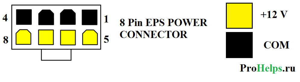
This cable was originally created for workstations to provide 12 volts of repeated power. But since many times have passed many processors require more nutrition and 8-pin cable is often used instead of a 4-pin 12 volt cable. It is often referred to as "EPѕ12V" cable.
4 + 4 pin EPS +12 volt power connector

 Motherboards can be with a 4-pin connector or a 8-pin 12 volt connector. Many food sources are equipped with 4 + 4-pin 12 volts cable, which is compatible with 4 and 8 continent contacts. A 4 + 4 Power cable has two separate pins 4 pieces. If you connect them together, 4 + 4 power cable, then you will have an 8-pin power cable that can be connected to an 8-pin connector. If you leave two parts separately, then you can connect one of the plugs of the 4-pin Motherboard connector.
6-pin PCI Express (PCIE) power cable connector

This cable is used to provide additional 12 volts for PCI Express Expansion Cards. This connector can provide up to 75 W PCI Express.
8-pin PCI Express (PCIE) power cable connector

PCI Express Specifications 2.0 released in January 2007 Added 8 pin PCI Express with power cable. It is just an 8-pin version of the 6-pin PCI Express with a power cable. Both are used mainly to provide additional video cards. The senior 6-pin version officially provides no more than 75 W (although it is unofficially, as a rule, can give much more), and the new 8-pin option provides a maximum of 150 W.
6 + 2 (8) PIN PCI Express (PCIE) power cable connector

Some graphics cards have a 6-pin PCI Express with power connectors and other 8-pin PCI Express connectors. Many power supplies are supplied with 6 + 2 PCI express power cable, which is compatible with both types of video cards. In 6 + 2 PCI Express, the power cable consists of two parts: 6-pin, and 2-plug. If you fold together these two parts, then you will have a full-fledged 8-pin PCI-Express connector. But if you split the connector into two parts, then you can only connect 6-pin.
CPU power connectors
CPU power comes from a device called Voltage Regulator Module (VRM), which is available in most motherboards. This device provides power to the processor (as a rule, through contacts on the processor socket) and produces self-calibration to suppress proper voltage to the processor. The design of the VRM module allows it to be powered by both from the incoming voltage +5 V and from voltage +12 V.
For many years, only +5 B is used, but since 2000, most VRM moved to +12 in due to lower requirements for working with such a voltage at the input. In addition, other components of the PC can also use a voltage of +5 V, which comes through a common contact on the nest of the motherboard, while only disk drives (in any case, it was up to 2000). Does VRM use on your board voltage +5 V or +12 B depends on the specific model board and the stress controller design. Many modern VRM are arranged in such a way as to receive at the voltage input from +4 V to +26 V, so the final configuration determines the manufacturer of the motherboard.
For example, someone in our hands got a FIC motherboard (First International Computer) SD-11, equipped with a regulator of SEMTECH SC114ABCSW voltage. This fee uses the +5 V voltage, converting it to lower in accordance with the needs of the CPU. Most motherboards use VRM two manufacturers - Semtech or Linear Technology. You can visit the sites of these companies and study the specifications of their chips in more detail.
The motherboard, which is spent on, used the Athlon processor 1 GHz Model 2 in the version with a slotted slot (Slot A) and according to the specification, required 65 W, at a nominal voltage of 1.8 V. 65 W at a voltage of 1.8 B corresponded to the current 36 , 1 A. When using VRM with an incoming voltage +5 in power 65 W corresponds to the current of total 13 A. But this alignment is obtained only under the condition of 100% of the voltage controller, which is impossible. Usually, the effectiveness of VRM is about 80%, thus, to ensure the operation of the processor, together with the voltage regulator, the current will be approximately equal to 16.25 A.
If we consider that other energy consumers on the motherboard are also used by the line +5 V - remember that the ISA or PCI cards also use this voltage - you can make sure how easy it is possible to overload the +5 in the power supply.
Although most of the VRM design solutions on motherboards are inherited from Pentium III and Athlon / Duron processors using +5 B regulators, most modern systems are used by VRM, designed to voltage +12 V. This is due to the fact that higher voltages reduce the current level. We can make sure that the example of AMD Athlon 1 GHz, about which already mentioned above:
| Current level depending on the incoming voltage | |||
| Power | Voltage | Tok Power | Current strength in Ampere taking into account the efficiency of the voltage regulator 80% |
| 65 W. | 1.8 B. | 36.1 A. | - |
| 65 W. | 3.3 B. | 19.7 A. | 24.6 A. |
| 65 W. | 5.0 B. | 13.0 A. | 16.3 A. |
| 65 W. | 12.0 B. | 5.4 A. | 6.8 A. |
As you can see, the use of the +12 in to power the chip requires a current of the force of only 5.4 or or 6.8 A, taking into account the effectiveness of VRM.
Thus, by connecting the VRM module on the motherboard to the power line +12 V, we could extract a lot of benefit. But, as you already know, the ATX 2.03 specification assumes only one +12 V line, which is transmitted through the main motherboard power cable. Even who lived a brief life, the auxiliary 6-pin connector was devoid of contact with the tension +12 V, so he could not help us. The current by force is more than 8 A by one wire of the 18th caliber from the line +12 in the power supply is a very effective way to melt the contacts of the ATX connector, which according to the specifications are designed for current not higher than 6 A when using standard Molex contacts. Thus, a fundamentally different solution was required.
Platform Compatibility Guide (PCG)
The processor directly controls the power of the current passing through the contact +12 V. Modern motherboards are designed to provide support for as many processors as possible, however, VRM circuits some boards may not provide sufficient food for all processors that can be installed in socket on the motherboard. To eliminate potential compatibility issues that can lead to an unstable PC work or even failure of individual components, Intel has developed a power standard called Platform Compatibility Guide (PCG). PCG is mentioned on most intel boxing processors and motherboards manufactured from 2004 to 2009. It was created for PC and system integrators to convey to them information about which requirements makes a power processor, as well as the motherboard compliance with these requirements.
PCG is a double-digit or three-digit designation (for example, 05a), where the first two digits mean the year when the product was presented, and the additional third letter corresponds to the market segment. PCG marking, including the third mark A, correspond to processors and motherboards related to low-end solutions (require less energy), while the letter B refers to processors and motherboards relating to the high-end market segment (require more energy ).
Motherboards that support High-End Class processors, by default, can also work with less productive processors, but not vice versa. For example, you can set the processor with PCG marking 05A in the motherboard having a 05B marking, but if you try to install the 05B processor in a fee having a 05A marking, you may easily encounter unstable operation of the system or other, more severe consequences. In other words, there is always the opportunity to establish a less productive processor in an expensive motherboard, but not vice versa.
| Recommendations for the power level along the line +12 V in accordance with the Intel Platform Compatibility GUIDE (PCG) labeling | |||||
| PCG code | Year | Market segment | CPU energy consumption | Permanent current over the line +12 in | Peak power over the line +12 in |
| 04A. | 2004 | Low-End. | 84 W. | 13 A. | 16.5 A. |
| 04b. | 2004 | High-End. | 115 W. | 13 A. | 16.5 A. |
| 05A. | 2005 | Low-End. | 95 W. | 13 A. | 16.5 A. |
| 05b. | 2005 | High-End. | 130 W. | 16 A. | 19 A. |
| 06 | 2006 | Everything | 65 W. | 8 A. | 13 A. |
| 08 | 2008 | High-End. | 130 W. | 16 A. | 19 A. |
| 09A | 2009 | Low-End. | 65 W. | 8 A. | 13 A. |
| 09B. | 2009 | High-End. | 95 W. | 13 A. | 16.5 A. |
The power supply must be able to withstand the peak load at least for 10 ms.
The power supply that corresponds to the required minimum on the +12 V line can provide stable operation of the system.
4-pin CPU power connector +12 V
To increase the current over the +12 V line, Intel has created a new ATX12V BP Specification. This led to the appearance of the third power connector, which was called ATX +12 V and was used to sum up the additional voltage +12 V to the motherboard. This 4-pin power connector is standard for all motherboards corresponding to ATX12V specifications, and contains contacts Molex Mini-Fit Jr. With forks such as "Mom". According to the specification, the connector complies with the standard Molex 39-01-2040, the type of the context - Molex 5556. This is the same type of contacts that is used mainly to power the ATX motherboard.
This connector has two contacts +12 V, each of which is designed for current to 8 A (or up to 11 A when using HCS contacts). This ensures the strength of the current 16 and in addition to the contact on the motherboard, and in the amount both connectors provide a current to 22 A along line +12 V. The location of the contacts of this connector is shown in the following scheme:
Connector +12 in processor power, frontal view and layout of contacts
Appointment of contacts on the +12 connector B is presented in the following table:
| 4-pin connector +12 B to power CPU | |||||
| Contact | Signal | Color | Contact | Signal | Color |
| 3 | +12 V. | Yellow | 1 | GND. | The black |
| 4 | +12 V. | Yellow | 2 | GND. | The black |
Using standard Molex contacts, each contact in the +12 B connector can be carried out with a strength of up to 8 A, 11 A with HCS contacts, or up to 12 A with Plus HCS contacts. Even though in this connectivity, the same contacts are used as mainly the current on this connector can reach higher values, since fewer contacts are used. By multiplying the number of contacts for the voltage, you can determine the limit power of the current according to this connector:
Standard Molex contacts are designed for current 8 A.
Contacts Molex HCS designed for current 11 A.
Contacts Molex Plus HCS Detached 12 A.
All values \u200b\u200bare indicated for a bunch of 4-6 contacts Mini-Fit Jr. When using wires of the 18th caliber and standard temperature.
Thus, in the case of using standard contacts, power can reach 192 W, which, in most cases, is sufficient even for modern productive CPUs. Consumption of greater power can lead to overheating and placing contacts, so in the case of the use of more "voracious" models of processors fork +12 B to power the processor should include Molex HCS contacts or Plus HCS.
The 20-pin main power connector and the processor power connector +12 into together provide the maximum current power level of 443 W (when using standard contacts). It is important to note that adding the connector +12 in allows you to use the full power of the power supply of 500 W, without risking to encounter overheating or melting contacts.
Adapter on the +12 connector in processor power
If a power Supply It does not have a standard connector +12 B to power the processor, and on the motherboard there is a corresponding socket, there is a simple way out of the problem - use the adapter. What nuances can we face in this case?
The adapter connects to the connector for peripheral devices, which is available in almost all of the BP. The problem in this case is that the connector for peripheral devices is only one contact +12 V, and the 4-pin CPU power connector is two such contacts. Thus, if the adapter assumes the use of only one connector for peripheral devices using it to ensure the voltage immediately on two contacts of the connector +12 B for the processor, then in this case we see a serious inconsistency between current requirements. Since the contacts on the peripheral devices are calculated on the current only at 11 A, the load exceeding this value can lead to overheating and placing contacts on this connectivity. But 11 A is below the peak current values \u200b\u200bto which the contacts should be calculated in accordance with the Intel PCG recommendations. This means that such adapters do not comply with the latest standards.
We made the following calculations: Given the effectiveness of VRM at the level of 80%, for the average of the processor consuming 105 W, the current level will be approximately 11 A, which is maxima for the peripheral power connector. Many modern processors have TDP over 105 W. But we would not recommend using adapters that use only one connector for peripheral devices, with processors having a TDP above 75 W. An example of such an adapter is shown in the following figure:

Adapter on the power connector CPU +12 V with connector for powering peripheral devices
8-pin CPU power connector +12 V
In the High-End Class Motherboards, several VRMs are often used to power the processor. To distribute the load between the additional voltage regulators, such boards are equipped with two sockets for the 4-pin connector +12 V, but physically they are combined into one 8-pin connector, as shown in the figure below. This type of connectivity was first presented in the EPS12V version 1.6 specification, released in 2000. Although initially this specification was focused on file-servers, the increased power requests for some high-performance processors for desktop PCs led to the fact that this 8-pin connector appeared in the PC world.

8-pin CPU power connector +12 V. Front view and contact configuration
Purpose of contacts of the 8-PIN CPU connector +12 B is provided in the following table:
| 8-pin CPU +12 power connector in | |||||
| Color | Signal | Contact | Contact | Signal | Color |
| Yellow | +12 V. | 5 | 1 | GND. | The black |
| Yellow | +12 V. | 6 | 2 | GND. | The black |
| Yellow | +12 V. | 7 | 3 | GND. | The black |
| Yellow | +12 V. | 8 | 4 | GND. | The black |
Some motherboards where 8-pin CPU power connector is used to ensure correct operation should receive voltage to all connectivity contacts, while most of the motherboards of this type can work, even if you use only one 4-pin power connector. In the latter case, four free contact will remain on the nest of the motherboard. But before running a computer with such a configuration of connectors, you need to read the manual of the motherboard user - most likely, it will be reflected, it is possible to connect one 4-pin power connector to the 8-housing socket on the board, or not. If you are using a processor that consumes more energy than one 4-pin power connector can provide, however, you will have to find a BP equipped with an 8-pin connector.
 Causes of why Flash Player does not work, and troubleshooting
 The laptop itself turns off, what to do?
 HP Pavilion DV6: Characteristics and Reviews
 Format representation of a floating point numbers How negative numbers are stored in the computer's memory
 Computer fries and does not turn on what to do?
 Why does not work mouse on a laptop or mouse?
 How to increase or decrease the scale of the page (font) in classmates?