Clock frequency. How to overclock the processor: the practical side of the question
"- In this train, no one knows anything!
- What else to expect foreigners from these loafers? "
Agatha Christie, Eastern Express.
So, gentlemen, it's time to change the tire, for 10 years the former generally accepted industrial standard. PCI, the first version of the standard of which was developed back in 1991, lived a long and happy life, in various hypostasses, as the basis for small and large servers, industrial computers, laptops and graphic solutions (we recall that AGP also leads its pedigree from PCI and It is a specialized and advanced option of the latter). But before talking about a novelty, like historic grandmothers, remembering the development of PCI. For, it was not once observed that, speaking of future prospects, it is always helpful to find historical analogies: PCI history
In 1991, Intel offers the basic version (1.0) of the PCI bus standard (Peripheral Component InterConnect - connection of the peripheral components). PCI is designed to replace the ISA (and later it is not very successful and expensive server extended EISA modification). In addition to significantly increased bandwidth, the new bus characterizes the possibility of dynamic configuration of the resources allocated by the attached devices (interrupts).
In 1993, the PCI Special Interest Group (PCISIG, a special PCI interest group, the organization that took care of the development and adoption of various standards related to PCI) publishes the updated 2.0 audit of the standard that has become the basis for the wide expansion of PCI (and its various modifications) In industry information technologies. Many well-known companies are involved in PCISIG activity, including the PCI generic team - Intel, who has presented the industry many long-playing, historically successful standards. So, the basic version of PCI (IEEE P1386.1):
- The clock frequency of the tire 33 MHz, uses synchronous data transmission;
- Peak bandwidth 133 MB per second;
- Parallel data bus with a 32-bit width;
- Address space of a 32-bit (4 GB);
- Signal level 3.3 or 5 volts.
Later the following key bus modifications appear:
- PCI 2.2 - 64-bit bus width and / or clock frequency 66 MHz are allowed, i.e. Peak bandwidth up to 533 MB / s.;
- PCI-X, 64-bit Version PCI 2.2 with increased to 133 MHz frequency (peak bandwidth 1066 MB / s.);
- Pci-x 266 (PCI-X DDR), DDR version PCI-X (effective frequency 266 MHz, real 133 MHz with transmission on both fronts of the clock signal, peak bandwidth 2.1 GB / s);
- PCI-X 533 (PCI-X QDR), QDR version PCI-X (effective frequency 533 MHz, peak bandwidth 4.3 GB / s.);
- MINI PCI - PCI with SO-DIMM style connector, is used mainly for miniature network, modem and other cards in laptops;
- Compact PCI - standard on the forms factor (modules are inserted from the end to the cabinet with a common tire on the rear plane) and the connector intended primarily for industrial computers and other critical applications;
- Accelerated Graphics Port (AGP) - high-speed PCI version optimized for graphic accelerators. There is no bus arbitration (i.e., only one device is permissible, except for the last, 3.0 version of the AGP standard, where devices and slots can be two). The transmission towards the accelerator is optimized, there is a set of special additional features specific for graphics. For the first time this tire appeared along with the first system sets for pentium processor II. There are three basic versions of the AGP protocol, an additional power specification (AGP Pro) and 4 data transfer rates - from 1x (266 MB / s) to 8x (2GB / s), including allowing signal levels 1.5, 1.0 and 0.8 volts.
We also mention the Cardbus - 32-bit version of the tire for PCMCIA cards, with a hot connection and some additional features, nevertheless having a lot of common with base version PCI.
As we can see, the main development of the tire goes in the following directions:
- Creating specialized modifications (AGP);
- Creating specialized forms of factors (Mini PCI, Compact PCI, Cardbus);
- Increasing bit;
- Increasing the clock frequency and the application of DDR / QDR data transmission schemes.
All this is quite logical, given the huge life of a similar universal standard. Moreover, items 1 and 2 do not work as to maintain compatibility with basic PCI cards, but items 3 and 4 are performed by increasing the original PCI connector, and allow the installation of conventional 32x discharge PCI cards. For example, we note that during the evolution of the tire there were also conscious loss of compatibility with old maps, even for the basic version of the PCI connector - for example, in Specifications 2.3 disappeared reference to support 5 volts of the signal level and supply voltage. As a result, server boards equipped with this modification of the tire can be injured when it is installed in them old, pasty-headed cards, although, from the point of view of the geometry of the connector, these cards are suitable for them.
However, like any other technology (for example, processor nuclei architecture), the tire technology has its reasonable scaling limits, when approaching which the throughput increase is increasingly and greater than the price. The increased clock frequency requires a more expensive wiring and imposes significant limitations on the length of the signal lines, the increase in the bit or the use of DDR solutions also entails a variety of problems that are eventually trimmed into the cost growth. And if in the server segment, solutions like PCI-X 266/533 will still be economically justified, then in consumer PC we did not see them, and I will not see them. Why? Obviously, ideally the bandwidth of the tires should grow synchronously with an increase in processor performance, while the price of the implementation should not only be maintained by the same, but also ideally decrease. On the this moment This is only possible when using new tire technology. About them today and let's talk: the era of serial tires
So, it's no secret that in our time, the perfect external interface, one way or another, is consistent. The times of stranded centeronixes were passed, and Tolstny (not overpowed) SCSI hoses - in fact, heritage before PCs. The transition occurred slowly, but correctly: first the keyboard and mouse, then the modem, then, after years and years - scanners and printers, camcorders, digital cameras. USB, IEE1394, USB 2. At the moment, all consumer external peripherals moved to consecutive connections. Not around the corner and wireless solutions. The mechanism is obvious - in our time it is more profitable to lay maximum functionality in the chip (hot connection, sequential coding, transmission and reception, data decoding, routing protocols, and error protocols, etc. necessary for squeezing the necessary topological flexibility and essential bandwidth from a pair of wires rather than deal with excess contacts, hoses with hundreds of wires inside, cheap soldering, shielding, wiring and copper. Nowadays, consistent tires become more convenient not only from the point of view of the end user, but from the point of view of the banal benefit - a bandwidth to multiply to the distance to divide the bucks. Of course, over time, this trend could not not spread on the inside of the computer - we already observe the first fruit of this approach - Serial ATA. Moreover, it is possible to extrapolate this trend not only on system tires (the main topic of this article) but also on the memory bus (it is rightly noted that a similar example was already - Rambus, but the industry fairly found it prematurely) and even the processor tire (potentially more good example - HT). Who knows how many contacts will be at Pentium X - perhaps less than a hundred, provided that half of them are land and nutrition. Time to slow down and clearly formulate the benefits of serial tires and interfaces:
- Favorable transfer of an increasing part of the practical implementation of the tire on silicon, which makes it easier to debug, increases flexibility and reduces development time;
- The prospect is organically used in the future other carriers of the signal, such as optical;
- Saving space (non-pocket miniaturization) and decrease in the complexity of the installation;
- It is easier to implement hot connections and dynamic configuration in any sense;
- The ability to highlight guaranteed and isochrony channels;
- Transition from shared tires with arbitration and unpredictable interrupts uncomfortable for reliable / critical systems to more predictable point-to-point connections;
- Best in terms of costs and more flexible from the point of view of topology scalability;
- This is not enough ??? ;-).
In the future, you should expect the transition to wireless tires, technologies similar to UWB (Ultra Wide Band) However, this is a matter of not the next year and not even five years.
And now, it's time to discuss all the advantages on specific example - new standard system bus PCI EXPRESS.The mass distribution of which on the PC segment and medium / small servers is expected in the middle of the next year. PCI Express - Only Facts
PCI Express - key differences
Let us detach the key differences of PCI Express from PCI:
- As repeatedly mentioned - the new tire is consistent, not parallel. Main advantages - cost reduction, miniaturization, better scaling, more favorable electrical and frequency parameters (no need to synchronize all signal lines);
- The specification is divided into a whole stack of protocols, each level of which can be enhanced, simplified or replaced without affecting the rest. For example, a different signal carrier can be used or routing can be abolished in the case of a selected channel only for one device. Additional control capabilities can be added. The development of such a tire will occur much less painful - an increase in bandwidth will not require changing the control protocol and vice versa. Quickly and conveniently develop adapted special purpose options;
- In the original specification, the possibilities of hot swaps of cards are laid;
- In the original specification, the creation of virtual channels is laid, ensuring the bandwidth and response time, QoS statistics collection (Quality of Service - quality of service);
- In the original specification, the possibilities of monitoring the integrity of the transmitted data (CRC) are laid;
- In the original specification, the capabilities of power management are laid.
So, more wide ranges Applicability, more comfortable scaling and adaptation, rich set of initially embossed capabilities. Everything is so good that I just can not believe. However, in relation to this tire, even the avid pessimists speak more likely rather than negatively. And this is not surprising - a candidate for a ten-year TRON of the general standard for a large number of different applications (starting from mobile and embedded and ending with the "Enterprise" servers or critical applications) is simply obliged to look impeccable from all sides, at least on paper :-). How it will be in the case - we will see them soon. PCI Express - how it will look
The easiest way to go to PCI-Express for standard architecture desktop systems looks like that:

However, in the future it is logical to expect the appearance of a certain PCI Express splitter. Then the union of the northern southern bridges will become quite justified. We give examples of possible system topologies. Classic PC with two bridges:
As mentioned, Mini PCI Express Slot is provided and standardized:

And the new slot for external replaceable cards, on the like cardbus, which is made not only by PCI Express but also USB 2.0:

It is interesting that there are two forms of factor of cards, but they differ not to thick as before, but width:

The solution is very convenient - first to make a two-storey installation inside the card much more expensive and more uncomfortable than to make a card with a rapid area inside, secondly, a full width map will eventually double the bandwidth, i.e. The second connector will not stand idle. From an electric or protocol point of view, the newcard bus does not carry anything new, all the functions needed for hot replacement or energy saving are already laid in the PCI Express.pci Express base specification - transition
To facilitate the transition, provides a compatibility mechanism with softwarewritten for PCI (devices, OS drivers). In addition, PCI Express connectors unlike the PCI are located on the other side of the section expansion card, i.e. Can coexist in one place with PCI connectors. The user will only have to choose which card he wants to insert. First of all, the appearance of PCI EXPRESS is expected in the initial server (two-processor) Intel platforms in the first half of 2004, then in the enthusiast class desktop platforms and workstations (in the same year). How quickly the PCI Express will be supported by other manufacturers of chipsets is not clear, however, NVIDIA and SIS respond to the question of applying, although they do not call specific deadlines. It has long been planned and prepared for the exit in the first half of 2004, graphic solutions (accelerators) from NVIDIA and ATI, equipped with built-in support for PCI Express X16. Many other manufacturers are active participants in the development and testing of PCI Express and also intend to submit their products until the end of 2004.
We'll see! There is a suspicion that the baby came out good.
In good way, PCI Express: Departure 2004, arrival 2014.
In this article we will talk about the causes of the success of the Tire PCI and give a description of high-performance technology that comes to shift - PCI Express tires. We will also consider the development history, hardware and software levels of the PCI Express tires, the features of its implementation and list its advantages.
When in the early 1990s. It appeared, then in terms of its technical characteristics, all the tires such as ISA, EISA, MCA and VL-BUS have significantly exceeded. At that time, the PCI bus (Peripheral Component InterConnect - the interaction of peripheral components), operating at 33 MHz, was well suited for most peripheral devices. But today the situation has changed in many ways. First of all, the clock frequencies of the processor and memory increased significantly. For example, the processors' clock frequency increased from 33 MHz to several GHz, while the PCI operating frequency increased only to 66 MHz. The emergence of technologies such as Gigabit Ethernet and IEEE 1394B threatened the fact that the entire PCI bus bandwidth can go to maintain a single device based on data technology.
At the same time, the PCI architecture has a number of advantages compared to predecessors, so it was completely irrational to be fully reviewed. First of all, it does not depend on the type of processor, supports buffer insulation, BUS Mastering technology (tire capture) and PNP technology in full. Buffer isolation means that the PCI bus is operating independently of the internal processor bus, which allows the processor bus items to function regardless of speed and load system Tire. Thanks to the tire capture technology, the peripheral devices were able to directly control the data transmission process over the bus, instead of expecting help from central processorWhat would affect system performance. Finally, Plug and Play support allows you to automatically configure and configure devices using it and avoid changing with jumpers and switches, which is pretty ported the life of ISA devices to the owners.
Despite the undoubted success of the PCI, this time it faces serious problems. Among them are limited throughput, lack of real-time data transfer functions and lack of support network technologies new generation.
Comparative characteristics of various PCI standards
It should be noted that the real bandwidth may be less theoretical due to the principle of operation of the protocol and the features of the tire topology. In addition, the total bandwidth is distributed between all devices connected to it, therefore, the more devices sits on the bus, the less bandwidth gets to each of them.
Such standard improvements as PCI-X and AGP were designed to eliminate its main drawback - a low clock frequency. However, the increase in clock frequency in these implementations led to a decrease in the effective bus length and the number of connectors.
The new generation of tires - PCI Express (or abbreviated PCI-E) was first represented in 2004 and was intended to solve all the problems that its predecessor faced. Today, most of the new computers is supplied with a PCI Express bus. Although the standard PCI slots in them are also present, but not far from the mountain is the time when the tire becomes the property of history.
Architecture PCI EXPRESS.
The bus architecture has a multi-level structure, as shown in the figure.
The tire supports the PCI addressing model, which allows you to work with it to all currently existing drivers and applications. In addition, the PCI Express bus uses the standard PNP mechanism provided for by the previous standard.
Consider the purpose of various levels of the organization PCI-E. At the bus level, the read / write requests are formed, which are transmitted at the transport level using a special batch protocol. The data level is responsible for noise-resistant encoding and ensures data integrity. The basic hardware level consists of a double simplex channel consisting of a transmitting and receiving pair, which together are called the line. The total speed of the tire of 2.5 GB / s means that the bandwidth for each PCI Express line is 250 MB / s in each direction. If you take into account the losses on the overhead of the protocol, then for each device about 200 MB / c. This bandwidth is 2-4 times higher than that that was available for PCI devices. And, unlike PCI, in the event that the bandwidth is distributed between all devices, it is fully in each device.
To date, there are several versions of the PCI Express standard that differ in their bandwidth.
PCI Express X16 bus bandwidth for different versions PCI-E, GB / C:
- 32/64
- 64/128
- 128/256
PCI-E tire formats
At the moment, various options for PCI Express formats are available, depending on the purpose of the platform - a desktop computer, a laptop or server. Servers that require greater bandwidth have more PCI-E slots, and these slots have a larger number of connecting lines. In contrast, laptops can have only one line for medium-speed devices.
Video card with PCI Express X16 interface.
The PCI Express extension boards are very similar to PCI boards, but PCI-E connectors are distinguished by increased clutch, which makes it confident that the fee will not slip out of the slot due to vibration or during transportation. There are several form factors of PCI Express slots, the size of which depends on the number of lines used. For example, a tire having 16 lines is indicated as PCI Express X16. Although the total number of lines can reach 32, in practice, most motherboards are currently equipped with a PCI Express X16 bus.
Maps of smaller form factors can be connected to the connectors for large without prejudice to performance. For example, the PCI Express X1 card can be connected to the PCI Express X16 connector. As in the case of the PCI bus, you can use the RCI Express extension to connect devices if necessary.
Exterior of connectors different types on the motherboard. From top to bottom: PCI-X slot, PCI Express x8 slot, PCI slot, PCI Express X16 slot.
Express Card
Express Card Standard offers a very simple way to add equipment to the system. The target market for the Express Card modules are laptops and small PCs. Unlike traditional extension boards desktop computersThe Express card can be connected to the system at any time while the computer is running.
One of the popular varieties of Express Card is the PCI Express Mini Card map, designed as a replacement of MINI PCI form factor. The card created in this format supports both PCI Express and USB 2.0. The dimensions of the PCI Express Mini Card are 30 × 56 mm. Map PCI Express Mini Card can be connected to PCI Express X1.
Advantages of PCI-E
The PCI Express technology allowed to obtain an advantage compared to the PCI in the following five regions:
- Higher performance. If you have only one line, the PCI Express bandwidth is twice as high as PCI. In this case, the bandwidth increases in proportion to the number of lines in the bus, the maximum number of which can reach 32. Additional advantage It is that tire information can be transmitted simultaneously in both directions.
- Simplify I / O. PCI Express uses the advantages of tires such as AGP and PCI-X and has less complex architecture, as well as comparative simplicity of implementation.
- Multi-level architecture. PCI Express offers an architecture that can adapt to new technologies and does not require a significant update of software.
- New generation I / O technology. PCI Express gives new features of data acquisition using simultaneous data transmissions technology providing timely receiving information.
- Easy use. PCI-E greatly simplifies the update and expansion of the system by the user. Additional formats Express boards, such as ExpressCard, significantly increase the possibility of adding high-speed peripherals to servers and laptops.
Conclusion
PCI Express is a tire technology for connecting peripheral devices that have replaced such technologies as ISA, AGP and PCI. Its application significantly increases the performance of the computer, as well as the user's ability to expand and update the system.
When overclocking the processor in manual mode You can manually set the desired system bus frequency, processor power supply, and select other overclocking parameters. This mode allows you to significantly increase the frequency of the processor.
Modern motherboards allow you to overclock the processor in manual mode using special utilities from Windows. However, this overclocking mode does not give all the features that there are BIOS motherboard. Therefore, the most appropriate will be the acceleration of the central processor by BIOS.
Consider the manual acceleration of the central processor on the example of a typical Bios maternal ASUS cards.
After entering the BIOS, you must select the Advanced tab (optional) of the main menu, and in it - the JumperFree Configuration item (JumperFree configuration) ( fig. 17.3). As a result, the processor acceleration menu opens ( fig. 17.4).
Fig. 17.3. Advanced Tab (optional) BIOS Main Menu
In order to access manual settings System bus frequencies, you need to select the MANUAL value (manual) parameter AI OVER-Clocking (intelligent acceleration) ( fig. 17.5). As a result, two new parameters will appear:
CPU Frequency (processor frequency) - allows in manual mode to adjust the frequency of the system bus with a step in 1 MHz (this frequency bonds to the frequency of the processor - increasing it, thereby increasing the CPU frequency);
Fig. 17.4. Advanced Tab (Advanced), JumperFree Configuration Item (JumperFree Configuration) Menu BIOS
PCI EXPRESS FREQUENCY pCI-Express Tires) - Used to set the PCI-Express tire frequency.
Fig. 17.5. Setting the AI \u200b\u200bOverclocking parameter (intelligent acceleration) to MANUAL (manual)
Before you begin overclocking, it is necessary to manually fix the PCI-Express bus frequency at 101 MHz, for this you need to set the PCI-Express Frequency parameter value (PCI-Express bus frequency) equal to 101.
After that, you can proceed to the processor acceleration procedure. To do this, it is necessary to gradually increase the value cPU parameter Frequency (processor frequency) ( fig. 17.6). The frequency of the process should be increased gradually, in 10 MHz increments.
After increasing the frequency, save all BIOS parameters and restart the system. If the OS load occurs, then it is necessary to test the stability of the system (see chapter 19). The system has been running stable, then you can quickly increase the processor frequency, if the system is unstable, then the frequency of the processor operation should be reduced in 1 MHz until the stable value is reached.
Fig. 17.6. Set the CPU Frequency parameter (processor frequency)
Processor acceleration is a long time-consuming process. Achieving the maximum stable frequency of the processor can take from several tens of minutes to several hours. It should also be said that each copy of the processor is accelerated in different ways, therefore even two identical processors used with the same motherboard and memory may have different maximum work frequencies.
The above example of manual overclocking does not allow to achieve the maximum possible frequency of the processor, but it will help to significantly disperse the CPU. To achieve higher overclocking frequencies, it is also necessary to change the system operation parameters such as a processor power supply voltage, a system bus multiplier, memory power supply. However, not all of the above parameters are available for adjusting in the BIOS of most system boards, so it is not always possible to dispersed the processor with these parameters.
The operation of any digital computer depends on the clock frequency that the quartz resonator determines. It is a tin container in which a quartz crystal is placed. Under the influence of electrical voltage in the crystal, electrical current fluctuations occur. This is the most frequency of oscillation and is called a clock frequency. All changes in logical signals in any computers chip occur after certain intervals called tactics. From here, we conclude that the smallest unit of time measurement for most of the computer's logic devices has a clock or another - a period of clock frequency. Simply put, at least one beat is required for each operation (although some modern devices have time to perform several operations for one clock). The clock frequency, in relation to personal computers, is measured in MHz, where Hertz is one oscillation per second, respectively, 1 MHz is a million oscillation per second. Theoretically, if your computer bus operates at 100 MHz, then it can perform up to 100,000,000 operations per second. By the way, it is not at all necessary that every component of the system must have done anything with each tact. There are so-called empty clocks (waiting cycles) when the device is in the process of waiting for an answer from any other device. For example, the operation of RAM and processor (CPU) is organized, the clock frequency of which is significantly higher than the RAM clock frequency.
Bigness
The tire consists of several channels for transmitting electrical signals. If it is said that the tire is thirty-dwinched, this means that it is capable of transmitting electrical signals by thirty two channels at the same time. There is one chip here. The fact is that the tire of any declared bit (8, 16, 32, 64) has, in fact, more channels. That is, if you take the same thirty-disconnect bus, then 32 channels are allocated to transmit the data itself, and the additional channels are intended for transmitting specific information.
Data transfer rate
The name of this parameter speaks for itself. It is calculated by the formula:
clock frequency * bit \u003d data rate
We will calculate the data rate for a 64 discharge system tire operating on a clock frequency of 100 MHz.
100 * 64 \u003d 6400 Mbps sec6400 / 8 \u003d 800 MB / s
But the resulting number is not real. A bunch of all kinds of factors affects the tires: inefficient conductivity of materials, interference, disadvantages of construction and assembly as well as much more. According to some data, the difference between the theoretical data transfer rate and the practical can be up to 25%.
The work of each tire is monitored specifically for this designed controllers. They are part of a set of system logic ( chipset).
Tire isa.
The ISA system tire (Industry Standard Architecture) is used since the I80286 processor. The extension boards socket includes the main 64-pin and optional 36-pin connectors. The tire is 16-bit, has 24 address lines, provides a direct appeal to 16 MB of RAM. The number of hardware interrupts - 16, DMA channels - 7. It is possible to synchronize the operation of the tire and processor with different clock frequencies. Clock frequency - 8 MHz. Maximum data transfer rate - 16 MB / s.
PCI. PERIPHERAL COMPONENT INTERCONNECT BUS - Tire connection of peripheral components)

In June 1992, appeared on the stage new standard - PCI, whose parent was Intel, and more accurately organized by the Special Interest Group. By the beginning of 1993, an upgraded PCI version appeared. In essence, this tire is not local. Let me remind you that the local bus is called the tire that is connected to the system bus directly. The PCI also uses the Host Bridge to connect to it, as well as the peer-to-peer bridge (peer-to-peer bridge) that is designed to connect two PCI tires. Among other things, PCI is the bridge itself between the ISA and the processor bus.
PCI clock frequency can be equal to or 33 MHz or 66 MHz. Bigness - 32 or 64. Data transfer rate - 132 MB / s or 264 MB / s.
The PCI standard provides three types of boards depending on the supply:
1. 5 volts - for stationary computers
2. 3.3 volts - for laptop computers
3. Universal boards that can work in both types of computers.
The large plus of the PCI tire is to satisfy the Plug and Play specification. In addition, in the PCI bus, any transmission of signals occurs packetwise where each packet is divided into phases. A package from the address phase begins, followed by one or several phases of data. The amount of phases of data in the package may be vague, but limited to the timer, which determines the maximum time during which the device can be used. Such a timer has each connected device, and its value can be set when configuring. An arbitrator is used to organize data on data transfer. The fact is that two types of devices can be on the tire - the master (initiator, master, leading) tires and subordinate. The master assumes control over the tire and initiates the transfer of data to the addressee, i.e. the subordinate device. A wizard or subordinate can be any device connected to the bus and the hierarchy this is constantly changing depending on which the device requested a data transfer on the transmission tire and to whom. For confonflial operation, the PCI tire responds the chipset, or rather North Bridge. But the PCI life did not stop his current. The constant improvement of video cards led to the fact that the physical parameters of the PCI tire began to be lacking, which led to the appearance of AGP.
Greetings dear friends, acquaintances, readers, admirers and other individuals. If you remember, we have raised a long time ago, but purely in theoretical cut, and after promised to make an article practical.
Given that overclocking the thing is quite difficult and ambiguous, then the articles in this cycle will be a pretty decent amount, and we have subsected it for one simple reason, it is simply impossible everywhere for writing, in addition to it, it is simply impossible everywhere.
Today we consider the most basic and typical side of overclocking, but with all this, at the same time, we will raise the most important and key nuances, ie, we will give an understanding how it works on the example.
Let's proceed.
Acceleration of the processor in the context [on the example of the P5E DELUXE card].
Actually, it can be said that overclocking is two: using programs or directly from Bios..
We will not consider program methods now on many reasons, one (and key) of which is the absence of stable adequate protection of the system (and, in general, iron, unless of course, cannot be considered) in case of installation of incorrect settings being directly in Windows. With acceleration directly from Bios. Everything looks much more reasonable, and therefore we will consider this particular option (besides, it allows you to set more settings and achieve greater stability and performance).
Options Bios."And there is quite a large number (and with the arrival UEFI They were even more), but the foundations and concept of overclocking retain their principles from year to year, that is, the approach to it does not change, except for the interfaces, in places the settings name and a number of technologies of this very acceleration.
I will consider here an example based on my old mat. Payment (about which I once told a long time ago) and the processor Core Quad Q6600.. The latter, actually, serves me faith and the truth already knows how many years (like a mat. Payment) and disinterested with me initially 2.4 Ghz.before 3.6 Ghz.What you can see in the screenshot of: 
By the way, who wondered how to choose such good and reliable mats. Payment we wrote, but about processors. I will proceed to directly the acceleration process, pre-removing the following:
A warning! Ahtung! Alarm! Hehnde Hech!
All responsibility for your subsequent (as well as previous) actions carry only you. The author only provides information, enjoy or not, you decide on your own. Everything written is checked by the author on a personal example (and repeatedly) and in different configurations, but this does not guarantee stable work everywhere, as well as does not protect you from possible errors In the course of the actions you have done, as well as any consequences that they can come for them. Be careful and think your head.
Actually, what do we need for successful overclocking? Yes, in general, nothing special is not counting the second item:
- First, first of all, of course, a computer with everything necessary, that is, the mat. Pay, processor and TP. Find out what the filling you have, you can download the aforementioned;
- Secondly, it is necessary, it is good cooling, for the acceleration directly affects the heat dissipation of the processor and the elements of the motherboard, i.e. without a good blowing, at best, acceleration will lead to instability of work or will not have his own strength, and in the worst case, something simply burns;
- Thirdly, by itself, knowledge is needed, to give which this article is designed, from this cycle, as well as the whole site ".
Queue of cooling, I would like to note the following articles: "", "", as well as ". Everything else can be found like this. We go further.
Since all the necessary theory, we have already disassembled in detail in detail, then I will immediately go to the practical side of the issue. I apologize in advance for the quality of the photo, but the glossy monitor, and on the street, in spite of the blinds, the same light.
That looks like Bios. On board my mat. payments (get into Bios., remind, on a stationary computer, can be button Del. At the earliest load stage, i.e, immediately after switching on or restarting):

Here we will be interested in the tab " Ai Tweaker"In this case, it is she who is responsible for overclocking and initially looks like a list of parameters with exhibited opposite the values" AUTO.". In my case, she looks like this:


Here we will be interested in the following parameters (I immediately give a description + my value with the comment why):
- Ai Overclock Tuner - Engaged in the autonomagon, allegedly with the mind.
In meaning " Standard " Everything works as it is, in the case of " Overclock 5%, Overclock 10%, Overclock 20%, Overclock 30%"Automatically increases the frequency to the appropriate percentage (and without warranties of stability). Then is interested in value ManualFor it will allow you to put everything with handles. Actually, it cost me. - CPU Ratio Setting. - Specifies the processor multiplier. You can set your value, when registering that the processor multiplier is unlocked. I put up here 9.0 Those, the most available from the unlocked multiplier value for my processor. You need to go similarly for your processor.
- FSB Frequency - Specifies the frequency of the system tire of the processor, it is the so-called base frequency. As you remember from the theoretical article, the final frequency of the processor is obtained from the value of this frequency multiplied by the multiplier (as it sounds! :)) Processor. Practice This in our process is the main thing and it is basically, we change to dispersed the processor. The value is selected by an experimental way, by combining with other parameters until the moment when the system works stably and the temperature mode suits you. In my case managed to take the bar in "400 x. 9 = 3600 MHz ". There were moments when I took 3.8 Ghz., But cooling simply did not cope in peak loads with heat dissipation.
- FSB STRAP TO NORTH BRIDGE - The parameter here is nothing more than a set of pre-installed delays, which from the point of view of the manufacturer optimally correspond specific frequency System tire, for a specific range of operating frequencies of the chipset. Here they are set for the northern bridge. Install the value FSB Strap It should be borne in mind that with a smaller value, smaller delays are set and the performance increases, and when the larger value is set, the performance drops slightly, but stability increases. The most relevant option during acceleration to ensure stability at high frequency FSB.. I had to choose a high meaning to achieve stability. In my case it 400
.
- PCIE FREQUENCY. - Indicates the frequency for the tire PCI EXPRESS.. Tire acceleration PCI EXPRESS. It is usually not practiced: meager winnings in speed does not justify possible problems with the stability of the extension cards, therefore fix the standard 100 mhz.in order to increase stability. And in my case, it is significant here 100 . I recommend it too.
- DRAM FREQUENCY. - Allows you to set the frequency of RAM. Parameters for selection are changing depending on the frequency FSB.. It is worth noting that often overclocking "rests" in memory, therefore it is considered to be optimal to set this frequency FSB. In which here you can choose the working (standard) frequency of your RAM, if, of course, you do not strive to overclock the memory. Meaning Auto " Often it is harmful and does not give due results from the point of view of stability. In my case exhibited " 800" In accordance with the characteristics of RAM. In your case, exhibit as you think right, but I recommend to watch your standard frequency through CPU-Z. And put it.
- Dram Command Rate. - Nothing other as a delay when exchanging commands between the memory controller of the chipset and memory. Qualitative memory modules are capable of working with delay in 1 Tact, but in practice it is rare and does not always depends on quality. For stability it is recommended to choose 2T.for speed 1T.So as the threshold of overclocking is big, then I chose here 2T.For in other provisions, it was not possible to achieve full stability.
- DRAM TIMING CONTROL - Specifies the timings of RAM. As a rule, if the goal is not worth overclocking RAM, here we leave the parameter " AUTO."If you catastrophically rested when accelerating into memory and do not break even in frequency, that is, it makes sense to try to overeat the values \u200b\u200bhere manually, refusing an automatic parameter. In my case, this is" Auto "Because in memory did not resume.
- DRAM STATIC READ CONTROL- Value " Enabled "raises the performance of the memory controller, and " Disabled. " - Reduces. Accordingly, stability depends on it. In my case "Disabled.
- Ai Slock Twister- If you take in free translation, this thing is controlled by the number of phases of memory access. Higher value ( Strong.) responsible for improving productivity, and lower ( Light) For stability. I chose " Light"(In order to increase stability).
- AI Transaction Booster - Here I read a lot of Bourgeois forums from which many data contradict each other, as in the Russian-speaking segment. Somewhere they write that this thing allows you to speed up or slow down the memory subsystem, adjusting the parameters of the foundations affecting in turn on the speed of the memory controller. Only, which adequately managed to understand what switches this in " Manual"We can customize" Perfomance Level.", playing with the value in the figure until the moment when you do not catch the stage of stability. I have this parameter stuck on 8- behold, for other values, the system behaved not stable.
- Vcore Voltage. - The function allows you to manually specify the power supply voltage of the processor. Despite the fact that it is this joy often allows you to increase productivity (more precisely to disperse the processor) by increasing the stability (without larger nutrition, you can hardly get a greater increase and quality of work, which is logical) when accepted, this parameter is an extremely dangerous toy in the hands of the non-professional and can lead to the output of the processor failure (if Bios. Of course, the protection function is not sewn, as they say, "from the fool" (c), as is C), and therefore it is not recommended to change the power of the processor, more than on 0.2
from regular. Generally speaking, this parameter should be increased very gradually and very small chambers, conquering all new and new heights of performance, until they are taking anything else (memory, temperature, and TP), or until you reach the limit in + 0.2
.
I would not recommend looking at my value, because it is really overpriced, but playing these games it allows me to be powerful cooling (the photo is not considered above, it is outdated yet in 2008 -th year), good BP, processor and mat. Be in general, careful, especially on budget configurations. My value 1,65 . You can learn your own voltage for your processor from the documentation or through CPU-Z.. - CPU PPL Voltage. - Something from for stability, but I have a very vague definition of what is this voltage. If everything works as needed, it is better not to touch. If not, you can raise small chairs. I mean, - 1.50 because it has been stable when I took the frequency 3.8 Ghz.. Again, it relies on my processor.
- FSB Termination Voltage. - Sometimes it is called the additional voltage of the processor or power supply voltage of the system bus. Its increases can in some cases increase the acceleration potential of the processor. 1.30 . Again, stability at higher frequency.
- Dram Voltage. - Allows you to manually specify the power supply voltage of the memory modules. It makes sense in rare cases to increase stability and conquer higher frequencies when overclocking memory or (rarely) processor. I have a slightly overpriced, - 1.85 with relatives 1.80 .
- North Bridge Voltage. and Soulth Bridge Voltage. - Specifies the supply voltage of the North ( North.) and southern ( Soulh.) Bridges, respectively. Raise with caution in order to increase stability. I am - me - 1.31 and 1.1 . Everything is for the same purposes.
- Loadline Calibration - A sufficiently specific thing that allows you to compensate for the variance of the nucleus nutrition while increasing the load on the processor.
In the case of acceleration you should always exhibit " Enabled "As you see in my screenshot. - CPU Spread Spectrum - The inclusion of this option is able to reduce the electromagnetic emission level of the computer due to the worst shape of the system bus and the central processor. Naturally, not the most optimal form of signals is able to reduce the stability of the computer. By the reduction in the level of radiation slightly and does not justify possible problems with reliability, the option is better to turn off ( Disabled.), especially if you are accelerating, i.e, as in our case.
- PSIE Spread Spectrum - similar to the fact that above, but only in the case of a bus PCI EXPRESS.., In our case - " Disabled.".
If you say quite simplistic, then, first of all, we change the multiplier and frequency FSB., relying on that final processor frequency that we would like to get. Next, we save the changes and try to boot. If everything happened, then check the temperatures and the computer at all, after which, in fact, or leave everything as it is, or we try to take a new frequency. If there is no stability frequency, i.e. Windows It does not load or show blue screens or something else, it is either returning to the past values \u200b\u200b(or slightly calm their appetites), or we select all other values \u200b\u200bas long as the stability is reached.
As for various types Bios., then somewhere functions can be called somehow otherwise, but the meaning is carried by the same, as well as the values \u200b\u200b+ the principle of overclocking remain constant. In general, if desired, we will figure it out.
In two words somehow so. It remains only to go to the afterword.
Afterword.
As you can see from the latest sentences, if you think about it, then quick acceleration in general is not a problem (especially with good cooling). I put up two parameters, several reboots and, - voila!, The cherished megahertz in your pocket.
Careful good acceleration at least 50 %, i.e. how in my case on 1200 MHz. Plus K. 2400 MHz., requires a certain amount of time (on average it is somewhere 1-5 hours, depending on the luckyness and desired final result), most of which takes the grinding of stability and temperatures, as well as a pack of patience, for the most annoying permanent The need to reboot to save and subsequent testing of new parameters.
I suspect that those who want to do a sim process will be a lot of questions (which is logical), and therefore, if they have it (as well as additions, thoughts, thanks, and so on), I will be glad to see them in the comments.
Stay with us! ;)
 Error appearance during program launch
 FRIGATE plugin for Firefox
 How to show hidden folders and files in Windows
 Ways how to make a screen on a laptop brighter or darker
 How to format a flash drive, disk protection
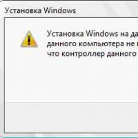 If installing Windows to this disc is not possible
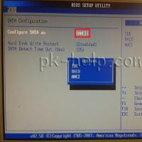 During installation of Windows "Make sure that the controller of this disc is included in the computer's BIOS menu.