How to measure the power of a radio signal of a certain frequency. The main parameters of the radio signal. Options and accessories for the power meters of the ANRITSU ML2490A series
Unfortunately, we have there is no accurate information when concrete goods are expected. It is better not to add to the parcel missing goods, or be ready to expect non-direct goods for several months. There were cases that the missing goods were excluded from the sale.
It makes sense to divide the parcels. One fully equipped, the other missing items.
So that after coming to the warehouse, the missing goods automatically reserved you, it is necessary proceed and pay His order.
IMMERSIONRC and 30DB radio signal power meter (35MHz-5.8GHZ)
The use of receiving-transmitting equipment without prior configuration and inspection on Earth threatens large troubles in the air. Radio power meter Immersionrc. Let you test and configure receiving-transmitting devices, as well as check the specifications of the antenna. Using this device, you can make comparative tests with different types of antennas, construct radiation pattern diagrams, as well as measure the output power of the transmitter using the built-in attenuator (power divider).
The power meter works with both, pulse and non-modulated, signals, and has a wide range of operating frequencies from 35 MHz to 5.8GHz, allowing you to test both video and RC systems.
The device will be an indispensable assistant, ranging from setting up self-made antennas and ending with the testing of the video signal to match the output power after the accident.
Do not hope for avosh! Test equipment!
Features:
Affordable price of the device, much cheaper than other similar equipment
Measurement of the emitted signal levels (for example, the UHF range, audio / video transmitter signal)
Calibration on all the main channels used in models, especially FPV
Dynamic range 50DB (-50DBM -\u003e 0DBM without using an external attenuator)
Output of information in MW or DBM
Included 30DB Attenuator and Adapter
Specification:
Frequency range: 1MHZ THRU 8GHZ, calibrated on the main channels for FPV / UAV
Power level without a benchmark: 50dbm thru 0DBM.
Adjustment: Programmable Attenuator Settings, Data Correction
Power supply: USB or DC source 6-16V
Calibrated equipment test: \u003e 100 in the ratio of frequency / power
Connector: standard high quality SMA
Weakening the coefficient of standing wave: 8GHz (typical)
Dimensions (LXWXH): L \u003d 90mm x w \u003d 52mm x H \u003d 19mm
Weight: 40g
Power supply: 6 - 16V DC
Current consumption: 100mA
Take The Guess Work Out of Your Setups with Proper Testing On The Ground Before Risking Problems in The Air.
The Immersionrc RF Power Meter Lets You Test and Tune Both Your Uplink and Downlink Setups in Power and Antenna Performance. You can Do Compararative Tests on Various Antenna Designs or Plot The Radiation Pattern, Even Test The Direct Output Power Of Your Transmitters using the Included Attenuator.
The Power Meter Works Wave Signals and A Wide Range of Frequencies from 35Mhz to 5.8GHz, Allowing You to Test Both Video and RC Systems.
This is an Invaluable Tool for anything from Hand Tuning a Video TX After A Crash for Proper Output Power. DON'T JUST GUESS WITH YUR INVESTMENT ... TEST IT.
Features:
Affordable RF Power Measurements, A Fraction Of The Cost Of Similar Equipment
Measure Pulsed, and Continuous RF Power Levels (E.G. UHF, and A / V DOWNLINKS)
Calibrated On All Common Bands Used for Modelling, and EsceciLY FPV
50DB of Dynamic Range (-50DBM -\u003e 0DBM Without The External Attenuator)
READOUT IN MW, OR DBM
Included 30DB Attenuator and Adapter
Specs:
Frequency Range: 1MHz Thru 8Ghz, Calibrated on Common Bands Used for FPV / UAV
Power LEVEL WITHOT ATTENUATOR: 50dbm thru 0DBM.
Adjustments: PROGRAMMABLE ATTENUATOR SETTING, READOUT CORRECTED
Power: USB, OR DC POWER JACK POWER SOURCE, 6V-16V
Calibrated AGAINST TRACEABLE TEST EQUIPMENT AT: \u003e 100 Frequency / Power Combinations.
Connector: Standard High-Quality SMA
Un-Attenuated VSWR: 8Ghz.
Attenuated VSWR: 8GHz (Typical)
Dimensions (LXWXH): L \u003d 90mm x w \u003d 52mm x H \u003d 19mm
WEIGHT (Grams): 40G.
Supply Voltage: 6 - 16V DC
Power Consumption: 100mA.
The task. 3.
Theoretical part. four
Basic provisions. four
Units of measurement of radio signals. five
Model Okamura Hat. 7.
Model Cost231-hut. eight
Model Cost 231-Walfish-IkgaGi. eight
Research results. eleven
The task
1. Conduct comparative studies of empirical models of attenuation of radio waves Okamura-Hat, Cost 231-hut and Cost 231 Walphish-IkgaGi at the given characteristics of the communication channel for the option 4 of the methodical instructions;
3. Problem Report Proof by the presence of the following sections: 1) Task, 2) Theoretical part (text is attached) and 3) Research results - two drawings with three graphs each.
Note: Calculation of the Cost231Uuel-Ikega gear models only for the case of direct visibility.
Theoretical part
Basic provisions
Radio wave studies in urban conditions are of great importance in the theory and technology of communication. Indeed, in cities living the largest number of residents (potential subscribers), and the conditions for the propagation of radio waves differ significantly from distribution in free space and semi-free space. In the latter case, the distribution over the regular earth surface is understood when the radiation diagram does not intersect with the earth's surface. In this case, with directional antennas, the impact of radio waves is determined by the formula:
L. = 32,45 + 20(lGD km + lGF MHC) – 10lGG PER - 10LGG PR, dB \u003d.
= L 0 -10lGG PER - 10LGG PR, dB. (one)
where L 0 is the main weakening of free space, dB;
d km - distance between the transmitter and the receiver, km;
f MHz - operating frequency, MHz;
G per and G Pr. - reinforcement coefficients of the transmitting and receiving antennas, respectively, DBI.
Basic weakening L 0. It is determined with isotropic antennas that emit evenly in all directions and are also taken. Therefore, weakening occurs due to dispersion of energy into space and small arrival at the receiving antenna. When using directed antennas, targeted by the main rays towards each other, the attenuation decreases in accordance with equation (1).
The task of the study is the definition of a radio channel, a carrier message (radio signal), which ensures the required quality and reliability of communication. Communication channel in urban environments is not a deterministic value. In addition to the direct channel between the transmitter and the receiver, there are interference interference due to numerous reflections from the ground, walls and roofs of structures, as well as the passage of radio signal through the building. Depending on the mutual position of the transmitter and the receiver, there are cases of lack of direct channel and for the received signal in the receiver you have to read the signal with the highest intensity. In a mobile connection, when the antenna of the subscriber receiver is at an altitude of 1 - 3 meters from the ground, these cases are dominant.
The statistical nature of the received signals require assumptions and restrictions within which decision making is possible. The main assumption is the stationarity of the random process with the independence of interference interference from each other, that is, the absence of mutual correlation. The implementation of such requirements led to
the separation of urban radio channels to the three main types: channels Gauss, Rice and Relay.
Gaussians channel is characterized by the presence of a dominant straight beam and small interference. The mathematical waiting for the weakening of the radio signal is described by normal law. This channel is inherent in television signals from a television bash when taking collective antennas at residential buildings. The Rice Channel is characterized by the presence of direct rays, as well as reflected and the ray buildings and the availability of diffraction on buildings. The mathematical expectation of the weakening of the radio signal is described by the distribution of Rice. This channel is inherent in networks with raised antenna over urban delicate buildings.
The relay channel is characterized by the lack of direct rays and the radio signal to the mobile station falls through the reassembly. The mathematical waiting for the weakening of the radio signal is described by the distribution of the relay. This channel is inherent in cities with high-rise buildings.
Types of channels and their distribution density functions are taken into account when developing signals spreading models in urban conditions. However, generalized statistics is not enough when calculating specific propagation conditions, in which the attenuation of signals depends on the frequency, from the height of the antenna suspension and the design characteristics. Therefore, when introducing cellular communications and the need for frequency-territorial planning, experimental studies of weakening in various cities and distribution conditions were carried out. The first results of research focused on mobile cellular communication appeared in 1989 (W.C.Y.LEE). However, even early, in 1968 (Y.okumura) and in 1980 (M.Hata) published the results of research on radio waveforms in the city, focused on mobile transkings and television.
Further studies were conducted with the support of the International Telecommunications Union (ITU) and were aimed at clarifying the conditions of the applicability of models.
Below are the models that have become the most common in designing communication networks for urban conditions.
Units of measuring radio signals
In practice, two types of measurement units are used to estimate the level of radio signals: 1) based on power units and 2) based on voltage units. Since the power at the output of the transmitter antenna for many orders of magnitude higher power at the input of the receiver antenna, then multiple power and voltage units are used.
The multiplicity of units is expressed in decibels (dB), which are relative units. Power is usually expressed in millivatts or in watts:
P dBmW \u003d 10 lg (P / 1 MW),(2)
R dBW \u003d 10 lg (P / 1 W).(3)
For example, a power equal to 100 W, in the above units will be equal to: 50 dBmW or 20 dBW.
In units of voltage as a basis, 1 μV (microvolt) is accepted:
U dBmKV \u003d 20 lg (u / 1 μV). (4)
For example, voltage equal to 10 mV, in the given relative units is 80 dBmKV.
Relative power units are used, as a rule, to express the radio signal level of the transmitter, relative voltage units - to express the signal level of the receiver. The relationship between the dimensions of relative units can be obtained on the basis of the equation P \u003d U 2 / Ror U 2 \u003d PR, Where R. There is an antenna input resistance, consistent with the line summing up to the antenna. Logarithming the given equations, and, taking into account the equations (2) and (4), we obtain:
1 dBmW \u003d 1 dBmKV - 107 dB with R \u003d.50 ohms; (5a)
1 dBmW \u003d 1 dBmKV - 108.7 dB with R \u003d.75 (5 B)
To express the power of the transmitter often use the characteristic - effective radiated power - EIM. This is the power of the transmitter, taking into account the gain coefficient (ku \u003d G.) Antennas:
EIM (DBW) \u003d P (DBW) + G (DBI). (6)
For example, a 100 W transmitter operates on an antenna with a gain of 12 dBi. Then EIM \u003d 32 DBW, or 1.3 kW.
When calculating the coating zone of the cellular communication station or the range of the broadcasting transmitter of the air television, the gain of the antenna should be taken into account, that is, to use the efficient radiated transmitter power.
The enhancement coefficient of the antenna has two units: dBI (DBI) - amplification coefficient relative to isotropic antenna and dBD (DBD)-Cheffer gain relative to the dipole. They are interconnected by the ratio:
G (DBI) \u003d G (dBD) + 2.15 dB. (7)
It should be taken into account that the reinforcement coefficient of the subscriber station antenna is usually taken equal to zero.
Okamura Hata Model
The primary version of the Okamura model and its co-authors is designed for the following conditions of application: the frequency range (150 - 1500) MHz, the distance between the mobile and base stations is from 1 to 100 km, the height of the base station antenna is from 30 to 1000 m.
The model is built on a comparison of weakening in a city with a weakening in free space, taking into account corrective components depending on the frequency, the height of the antennas of basic and mobile stations. The components are presented in the form of graphs. Large distances and heights of base stations are more suitable for broadcasting than for cellular communication. In addition, the resolving ability of graphs is low and less convenient than an analytical description.
The hut approximated the vacuum graphics by analytical ratios, reduced the frequency range to 1500 MHz (Occamuses it has been overstated and did not respond to the accuracy of the weakening estimate), reduced the range of distances from one to twenty kilometers, and also reduced the height of the base station antenna to 200 meters and addressed the clarification In some components of the valve models. As a result of the modernization of the hut, the model was called Okamura Hut and is popular for assessing the weakening of TV signals and in the cellular range up to 1000 MHz.
For the city weakening power L. In decibels (dB) describes the empirical formula:
L, dB \u003d 69,55 + 26.16 LGF - 13.83LG +(44.9-6,55 lG D- A ( ), (8)
where f. - frequency in MHz,
d. - the size of the basic and subscriber (mobile) station in km,
The height of the suspension of the Basic antenna and subscriber stations.
In formula (8) component a ( ) Defines the effect of the altitude of the subscriber station antenna to attenuate the signal power.
For the middle city and the average building height, this component is determined by the formula:
a ( ) = (1.1 LGF - 0.7) - 0.8, dB. (nine)
For the city with high buildings a ( ) Determined by the formula:
a ( ) = 8,3 (lG 1,54. ) 2 - 1.1 for f.< 400 МГц; (10)
a ( ) = 3,2 (lG 11,75 ) 2 - 5 for f.\u003e 400 MHz. (eleven)
In the suburban area, the loss when the signal propagation is longer dependent on the frequency than from the height of the subscriber station antenna, and, because the component Δ is added to the equation (8), taking into account equation (9) L, dB.Defined by equation:
Δ L, dB. = - 5,4 – (lG (0.036 f)) 2. (12)
In open areas Δ L, dB.with isotropic antennas is described by the equation:
Δ L, dB. = - 41 – 4,8 (lGF.) 2 + 18,33lGF.. (13)
The disadvantage of the Okamura-Hut model is to limit the frequency range to 1500 MHz and the inability to use it for a distance of less than one kilometer.
Within the framework of the Cost 231 of the European Union (Cooperation for Scientificand Technical Research), two models have been developed, which eliminated the noted flaws of the Okamura-Hut model. These models are discussed below.
Model COST231-Hut
1
The model allows you to estimate the weakening by the formula:
L.= 46,3 + 33,9 lG F -13,8 lGH B - A (H a) + (44,9 – 6,55lGH B.) lG D + C, dB, (14)
where FROM\u003d 0 for medium cities and suburban areas and FROM\u003d 3 for centers of large cities.
This model is not suitable for estimating the wavelength of the signal at distances between subscriber and base stations less than 1 km. At short distances, the nature of the development is more strongly manifested. For these cases, the Cost231-Waltich-IkgaGi model has been developed.
The main parameters of the radio signal. Modulation
§ Signal power
§ Specific signal 
§ Signal duration T. determines the time interval during which the signal exists (differing from zero);
§ Dynamic range is the ratio of the greatest instantaneous signal power to the smallest:
§ The width of the signal spectrum F - the frequency band, within which the main signal energy is concentrated;
§ The signal base is a product of the signal duration to the width of its spectrum. It should be noted that between the width of the spectrum and the duration of the signal exists inversely proportional dependence: the shorter the spectrum, the greater the signal duration. Thus, the magnitude of the base remains almost unchanged;
§ Signal / noise ratio equal to the ratio of the power of the useful signal to noise power (S / N or SNR);
§ The volume of the transmitted information characterizes the bandwidth of the communication channel necessary to transmit the signal. It is defined as a product of the spectrum width on its duration and dynamic range.
§ Energy efficiency (potential noise immunity) characterizes the accuracy of the transmitted data when exposed to the signal of additive white Gaussian noise, provided that the sequence of characters is restored by an ideal demodulator. Determined by the minimum signal-to-noise ratio (E b / n 0), which is necessary for transmitting data through the channel with a bug that does not exceed the specified one. Energy efficiency determines the minimum power of the transmitter necessary for acceptable operation. The characteristic of the modulation method is the energy efficiency curve - the dependence of the probability of an ideal demodulator error from the signal-to-noise ratio (E b / n 0).
§ Spectral efficiency - the ratio of the data rate of data to the used bandwidth of the radio channel.
- AMPS: 0,83.
- NMT: 0.46.
- GSM: 1.35
§ Resistance to the effects of the transmission channel characterizes the accuracy of the transmitted data when exposed to a signal of specific distortions: fading due to multipath propagation, the limitation of the band, focused in frequency or time of interference, the Doppler effect, etc.
§ Requirements for the linearity of amplifiers. To enhance signals with some modulation types, nonlinear class C amplifiers can be used, which makes it possible to significantly reduce the power consumption of the transmitter, while the level of uncommon radiation does not exceed the permissible limits. This factor is especially important for mobile systems.
Modulation (Lat. modulatio - dimension, rhythm) - the process of changing one or more parameters of high-frequency carrier vibrations by the law of a low-frequency information signal (messages).
Transmitted information is laid in the control (modulating) signal, and the role of the information carrier performs a high-frequency oscillation called carrier. The modulation, thus, is the process of "landing" of information oscillation on a well-known carrier.
As a result of the modulation, the spectrum of the low-frequency control signal is transferred to the high frequency area. This allows you to configure the functioning of all receiving-transmission devices at different frequencies when organizing the broadcasting device so that they "do not interfere" each other.
The carriage of various shapes (rectangular, triangular, etc.) can be used as a carrier, but harmonic oscillations are most often used. Depending on which of the parameters of the carrier oscillation changes, distinguish the type of modulation (amplitude, frequency, phase, etc.). The modulation of the discrete signal is called digital modulation or manipulation.
7.9. Measurement of the parameters in radio frequency systems Measurement of the function BER (C / N)
In the modern measuring method, BER uses various schemes from which two main ones can be distinguished.
Fig. 7.16. The diagram of the method of a rebuilt attenuator.
In this method, the receiver's radio frequency path includes a rebuilt attenuator, with which additional attenuation is made, and the stability of the reception signal is made constant for the entire measurement time. Signal and noise levels are measured using a power meter, while the noise measurement in the intermediate frequency path of the receiver without filtering gives a value greater than the actual noise power in the path of the path. Therefore, when measuring power, additional filters are used, configured to the frequency working strip.
The BER error parameter is measured by the digital channel analyzer.
The main disadvantage of the method is the assumption of the constant power of the useful signal during the entire measurement period. In real conditions, the level of the useful signal undergoes significant oscillations due to the multipath distribution of radio waves and changes in the distribution conditions. For this reason, the C / N ratio may also change, while even the change in C / N per dB can cause the change of BER by order. Thus, this method does not allow to provide the required measurement accuracy, especially small BER values.
2. Ber measurement interference method (C / AT), the diagram of which is shown in Fig. 7.17, uses a special device - the analyzer / simulator of the C / N parameter, which implements the measurement of the power level of the useful signal C when making a specified noise level n, which ensures high accuracy of determining the C / N parameter. In this method, the analyzer / simulator automatically adjusts the level of the noise made, while the measurement accuracy of the BER characteristics (C / AT) can reach ~ 1SG12 values. In conclusion of this consideration of the BER function (CIN), we note the following.
1. Conditions of theoretical and practical dependences of the substance / n) show that practical dependencies differ from theoretical in that the BER's practical values \u200b\u200brequire a greater relation to C / N. This is due to various causes of the deterioration of the parameter in the paths of intermediate and radio frequency.
2. In practice, the contributions of the radio and intermediate frequency paths are comparable between themselves, with a digital information transmission system at a speed of up to 90 Mbps, the following values \u200b\u200bof the deterioration of the BER parameter are observed.

Fig. 7.17. Ber Measuring Interference Measurement Scheme (C / N)
Deterioration in the intermediate frequency path:
Errors in phase and amplitude of the modulator - one dB;
Intersimalistic interference related to the operation of filters - 1.0 dB;
The presence of phase noise is 0.1 dB;
Differential coding / decoding procedures - 0.3 dB;
Jitter (phase trembling) - 0.1 dB;
An excess of the demodulator noise band - 0.5 dB;
Other reasons (effect of aging, temperature instability) - 0.4 dB.
So, in the amount in the PC tract, the deterioration of the Ber value can reach 2.5 dB. The deterioration of BER in the radio frequency path:
Nonlinearity effects - 1.5 dB;
Deterioration associated with the restriction of channel bandwidth and the delay group time - 0.3 dB;
Interference in adjacent channels - 1.0 dB;
The deteriorations associated with the effects of attenuation and the appearance of an echo signal - 0.2 dB. Total, in the RF radio frequency path, the deterioration of BER will be 3 dB, that is, in the system
Translations The deterioration of BER can reach -5.5 dB.
It should be noted that in the figures. 7.16, 7.17 did not consider the purpose of equalizers in digital radioacts.
Measurement of frequency and power in radio frequency paths.
Measuring the frequency and power of the useful radio signal are implemented in practice the following methods:
1) used frequency meters and power meters,
2) Spectrum analyzers are used with marker measurement functions.
In the second method, the marker is moving along the spectral characteristic while simultaneously displaying the values \u200b\u200bof the frequency and power parameters and the power of the utility radio signal.
To expand the capabilities of measurement of power parameters, modern spectrum analyzers provide smoothing spectral characteristics, noise filtering, etc.
Analysis of the operation of equalizers.
Compared with radio systems, as a radio signal transmission environment, has characteristics, accidentally changed over time. Due to the wide use of digital radio communication systems and increased requirements for the accuracy of their transmission in the receiving devices, equalizers are included, which make it possible to drastically reduce the effect of multipath distribution (signal alignment) and group delay time (auto adjustment). When using digital modulation methods for high-frequency signals, developers have faced the difficulties of accurately configuring modems and other channel-forming devices in the radio frequency path. In this case, equalizers act as elements of compensation of possible nonlinearities in the devices of the radio frequency transmission path. In modern radio frequency information transmission systems, there are two main types of attenuations associated with radio frequency distribution factors.
1) Linear attenuation, which is a frequency-independent uniform decrease in the amplitude of the signal from the signal distribution factors. Linear attenuation is usually due to the natural factors for the spread of electromagnetic waves:
With end-to-end distribution in forest arrays;
When distributed in the atmosphere in the presence of hydrometeors (rain, snow).
2) attenuation due to multipath distribution of radio signals.
These two factors change the amplitude of the useful signal, leading to a change in the value of the C / N ratio, which ultimately affects the BER error parameter. Changes in the structure of the beneficial signal associated with these two attenuations are compensated by equalizers. As you know, the basis of the operation of any equalizer is the use of a narrowband cutter filter to eliminate the nonlinearity of the useful signal. The primary parameter of measurements is the dependence of the depth of filtering from the frequency at a given parameter Ber, obtained in various reviews the name of the curve M or curve W (Fig. 7.18).

Fig. 7.18. Curves m for cases of absence and availability of equalizer.
To obtain a curve m, various conditions of the signal passing are usually simulated, which are compensated by the equalizer and in the compensation process is constructed curve M of the measurement scheme is presented in Fig. 7.19.
As a result of measurements, diagrams are obtained in the form of double-sided curves M, of which one is unhealthy (showing the ability of the equalizer filter to ensure the depth of filtration at a given frequency sufficient to align the structure of the benefit signal) and the other - hysteresis (showing the filter performance when it is necessary if necessary First increase, and then reducing the filtering depth parameter). In practice, both types of curves are essential for analyzing the operation of the equalizer.

Fig. 7.19. Scheme measurement curves m
Measurements of the parameters of the non-uniformity of the phase-frequency characteristics and group delay time.
The non-uniformity of the phase-frequency characteristic (FCH) of the radio frequency path is determined by group time of the delay (GVZ) from the formula:
The direct measurement of the dependence of the phase shift from the frequency F (w) and the subsequent differentiation of the obtained dependence is implemented, as a rule, for systems with a low level of phase noise, however, for radio communication systems, phase noises in the channel are present, which leads to non-uniformity of the FCH and the change in GVZ. Typically, the GVZ measurements are carried out during receiving and trial testing of radio systems and take into account possible deviations in the operation of the transmitter, receiver, the antenna devices and the conditions for the distribution of the radio signal. The paper describes two methods of GVZ measurements based on the use of composite radio signals.
Measurement of resistance parameters to linear damping and attenuation associated with multipath distribution of radio signals
Radio signal parameters are changed due to linear attenuation and attenuation caused by multipath propagation of radio signals. When conducting factory tests, a permissible limit of linear attenuation is introduced, not exceeding 50 dB for Ber \u003d 10 ~ 3. To compensate for linear attenuation, equalizers are used as part of the transmitter / receiver. The operation of the equalizer compensating for linear attenuation can be measured using tunable attenuators.
When measuring the damage resistance parameters associated with the multipath propagation of radio signals, it is possible to use the state chart and eye diagrams, which displays:
Status diagram - cross-interference signals / q are displayed as an ellipse,
The eye chart - the multipath phenomenon is displayed by the displacement of the centers "Eye" from the center to the edges.
However, the status diagram and the eye chart do not provide all the necessary measurement specification. To carry out practical measurements of the effectiveness of compensation of the multipath signaling, methods that are consistent with compensation methods are used. Since it is practically impossible to predict the appearance of a multipathistic propagation factor, consideration of the effects of this factor are carried out by methods of stressful effect, that is, by simulating the phenomenon of multipath signal propagation. As noted in the work, two models of imitation of multipath signal propagation are used.
1. Dvukhavoy model. The modeling principle is reduced to the theoretically reasonable assumption that the attenuation is associated with two-beamistic interference, and the interfering beam has a delay (for the reflected beam) in time. From the characteristics of non-uniformity frequency response (amplitude-frequency characteristics) and GVZ for two-beam radio propagation follows:
Reduction of amplitude with a change in frequency;
Changes in GVZ and ACH in the event of a minimum phase (when the main radar has a greater amplitude);
The change in the frequency response and GVZ in the case of a non-cellular phase (when the resulting beam after interferences two rays exceeds the main signal over the amplitude).
2.Regless model. Since the two-beam model does not describe the phenomenon of amplitude modulation and the occurrence of weak patterns within the working frequency range, as a result of which the amplitude of the useful signal is deflected within the operating range, even if the node of the beats is outside the operating range, the three-beam model is used to take into account The effect of amplitude shift. Usually, the two-beam model is used when conducting quality measurements, and three-beam - for accurate measurements.
Analysis of intermodulation interference.
When distributing radio signals in the path, intermodulation signal interactions occur during multiplexing and demultiplexing, as well as when the nonlinearities of the channel-forming devices are influenced in the path. Typically, intermodulation distortions have a rather low level - less than 40 dB relative to the level of the useful signal. However, control of intermodulation distortion and elimination of their causes ensures in some cases a solution to the problem of interference in adjacent channels. Analyzers of the spectrum use to analyze intermodulation.
Measurements of the characteristics of channel-forming radio frequency paths.
In addition to integrated measurements, in practice, measurements of the characteristics of channel-forming radio frequency tracts are widely used, the knowledge of which is necessary when designing and operating radiotechnical information transmission systems. In addition to measuring frequency and power in the service area, there is a need to measure the antenna systems, the level of thermal noise, the stability of the frequency of the specifying generators, phase jitter, parameters of modems and amplifier paths together with filtering devices.
Measurement of antenna systems.
The antenna-feeder devices in the composition of the radio frequency tract play an extremely important role. Main parameters: radiation power, radiation diagram in appropriate planes, amplification coefficient, impedance, etc., usually calculated and measured at the stage of production of antennas. In the process of operation, important parameters are
Running wave coefficient (CBW): CBW \u003d Umin / Umax, (7.38)
Coefficient of standing wave (CWS): KSV \u003d 1 / KBV, (7.39)
The level of return loss against antenna entrance, where Umin and Umax are minimal and maximum voltage in the feeder line.
In the event of an ideal path negotiation: the output of the transmitter is the feeder - an antenna input, CBW \u003d 1 (since all the energy from the transmitter exit is sent to the antenna and at the same time £ / min \u003d umach), in the case of Umin \u003d O, KSV \u003d oo kbv \u003d 0 - In the feeder, there is a standing wave mode, which is unacceptable.
 In the real case, the KSW can take values \u200b\u200bof 1.1 ... 2, that is, the CBW \u003d 0.5 ... 0.9. In the radioacts of digital information transmission systems with digital modulation types, a small level of return loss is required, that is, the minimum KSV -1.1 value when the mode in the feeder line is close to a high degree of matching.
For example, for radio relay communication lines that use the modulation 64 QAM, the recommended level of suppression of return loss from the antenna is 25 dB and higher. To measure return losses, a diagram shown in fig is typically used. 7.20.
From the microwave oscillation generator, a signal is sent to an antenna through a passive directional dismount. If the wave reflected from the inlet, electromagnetic oscillations through the directional coupler fall into the spectrum analyzer (or to the selective receiver), where the level of reflected power is measured. To reduce the level of reflected power, the analogue of the antenna-feeder tract is implemented. When used in practice, instead of an analyzer of the power meter spectrum, the measurement accuracy drops, since, together with the reflected signal, the power meter takes into account the level of noise associated with external influences on the radio channel in the specified operating frequency range.
Measuring the level of own thermal noise of the elements of the radio frequency path.
As the noise level increases, intersomol distortion of digital signals increases sharply and the BER value increases. In the status diagrams and eye charts, this is expressed in increasing the size of the point of displaying the state and the effect of "eye closing". Measuring noise of various devices in the row path is performed at the operation phase to localize the light noise level. Given that the own noises of various devices of the radio frequency path are small, differential methods use differential methods. To do this, the test signal mixes the interfering single-frequency signal and then measure the noise measurements along the difference in the interfering signal and noise. This method is used when measuring low-power noise. As an example in Fig. 7.21 shows the results of noise measurements against the interphoring single-frequency signal for modulation 16 QAM with a signal / interference with / i \u003d 15 dB, while, as can be seen from the figure, the noise level growth leads to an increase in the dimensions of the points on the state chart and the effect of the eye closing »On the eye chart.

Fig. 7.21. Examples of the state diagram and eye diagram when measuring noise with C / 1 \u003d 15 dB.
Measurements of phase jitter.
 An important parameter for measuring radiofrequency sections with digital modulation is a phase trembling signal of the parameter generators / transmitter, the so-called jitter (Jitter). For the analysis of the jitter, the state diagram is effective, since the eye chart is not sensitive to it. If the path appears a phase shivery signal, then
Fig. 7.22, an increase in the dimensions of the states of states occurs. To eliminate problems, connections when measuring the jitter with the presence of jitter, additional measurements of the parameters of the operating generators are used and eliminated faults.
Measurement of modem parameters.
To measure the modem parameters, analyzers are usually used to measure signals in the form of status diagrams and eye diagrams, which give the most complete information about the structure and changes in the digital modulation parameters. In fig. 7.23 As an example, the state diagrams and the eye chart for the case of quadrature amplitude modulation with 16 QAM 16 states are shown, of which:
The erosion of the points of the state chart indicates the effects of noise;
Distortion of the size "Eyes" indicates possible disorders in the operation of the digital channel (for example, the emergence of intersomol distortion).

Fig. 7.23. An example of a state chart and eye chart for the case of AM with 16 QAM states
Consider the following types of modem disorders and the corresponding diagrams.
1. The synchronization in the digital channel.
Global fault / disabling demodulator or phase synchronization violation can lead to a violation of the matching between the modulator and the demodulator and the signal disappearance in the transmission system. In this case, the status diagram is a random distribution of signals at the corresponding levels of modulation, the "eye" of the eye chart is completely closed (Fig. 7.24).

Fig. 7.24. An example of a synchronization loss in a digital channel: The status diagrams is a random distribution of signals at the corresponding levels of modulation, the "eye" of the eye chart completely closes.
2. Activation of the modulation / demodulation level parameters.
In fig. 7.25 shows a status diagram from which it follows that when modulating / demodulation levels are unbalanced by the signal amplitude. Changes in the status diagram may indicate the nonlinearities of the modulator or impaired DAC.

Fig. 7.25. An example of a violation of the installation of modulation / demodulation parameters.
3. Industion of orthogonality I and Q vector demodulator.
One of the common faults in the mode of the modem is the violation of the demodulator, when the vectors I and Q of the polar coordinates of the demodulator are not strictly orthogonal. This leads to a non-compliance with the states of the orthogonal grid of coordinates on the state diagram (Fig. 7.26).
 This malfunction may be accompanied or not accompanied by an error of phase synchronization in the carrier recovery circuit. In the absence of an error, the result of the impact of this malfunction on the eye diagram is reduced to the "Eye" closure on the diagram on the signal I and the absence of any change on the Q diagram. If there is an error "Eyes" of both charts will be closed. It should be noted that the analysis of the eyelid chart alone does not allow the cause of the cause of the fault, since this diagram completely coincides with the eye chart in the presence of a high level of additive noise in the channel. A reliable determination of the cause of the fault in this case can only be given a state chart. The elimination of the described fault requires adjustment of the demodulator in terms of the orthogonality of signals I and Q. On the state diagram of fig. 7.27 The presence of an error of phase synchronization of 2.3 degrees is noted.

Fig. 7.27. An example of a phase synchronization error appearance.
Measurement of the parameters of the amplifiers in the row path.
The main measured parameters of the operation of amplifiers in the composition of the radio frequency path are:
Noises made by amplifiers;
The parameters of the nonlinearity of the amplifying sites.
The amplitude overload can lead to the transition of the amplifier into nonlinear mode and, as a result, a sharp increase in the probability of the error in the digital transmission system. The use of state diagrams and eye diagrams makes it possible to estimate the reasons for the decline in radio quality parameters (nonlinear distortions lead to the vanity of the points of the state chart and the closure of the "eyes" of the eye chart).
 How to pay a domain name
 Domain zone of tokelau islands
 What is domain what problems may be
 Yandex Wordstat: detailed instructions for using the service and grouping operators and a complicated request
 Editing DBF files
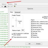 Xenu Link Sleuth - What is this program how to use the Xenu program
 Methods Copy and insert text from keyboard without using mouse