That PCI Latency Timer in BIOS. Joint open project. Power Management SETUP section
BIOS contains quite a lot of settings, to figure out which is not always easy, since reference Information For some functions, there is sometimes absent or does not help clearly understand the principles of their work. Therefore, many users are asked by a natural issue: PCI Latency Timer, what is it? Let's figure it out why you need this function and how to configure it correctly.
This BIOS parameter determines how long the device is connected to the PCI bus, hold it for your own needs, for transferring its data. Before the expiration of this time (the number of clocks), all other devices that use the PCI bus will not be able to take advantage of it. By default, the value of this function is 32 or 64 clocks, and in most cases it can be painlessly increased. The minimum value is 32, while the step of the cycle used can be consistently increased by 32 clock (64, 96, and so on), up to 224.
Possible values \u200b\u200boption
The maximum value of this function can be set to 248.
How to configure this parameter
Increasing the PCI Latency Timer value helps to increase the efficient bandwidth of the tire of the same name, which in certain cases can lead to wrong work Some high-speed devices that transmit and receive large amounts of information. For example, similar problems often occur at RAID controllers.
Nevertheless, it is recommended to try to increase the value of this parameter, especially if some extension cards using a PCI connector are installed in the computer. In this case, it is necessary to increase the value of the PCI Latency Timer in order to start loading the operating system, after which it is closely tracking the performance of the computer and its software.
If everything is functioning normally, then it is possible to consistently increase the value of PCI Latency Timer to, approximately 160 clocks and even higher, if there is a serious need. On the other hand, when troubleshooting in the operation of PCI devices, it is necessary to reduce the value of the above parameter, up to 64 or even 32 clocks. Such a need arises when the PCI bus uses many devices, some of which need priority access to this bus for unmistakable operation. Therefore, it should be remembered that by setting the PCI Latency Timer parameter to 32, such problems can be eliminated.
PCI-TO-DRAM PREFETCH
When the PCI device, working in the bus marscript mode, performs memory access, one byte with a given address comes into the internal buffer of the controller. But if you enable this option, several subsequent bytes will be read into the buffer, so the next PCI device query will be completed without memory access. For sound cards and FireWire controllers, it is especially important.
Read Around Write.
As you know, most (up to 90%) of memory requests are associated with reading data, and not with a record. Nevertheless, the memory record is necessary, but the tire does not allow both operations at the same time. Therefore, if you need to write at least one byte, any reading process will be interrupted. That this does not happen, there is a "Read Around Write" -BUFER, in which data comes that require subsequent placement in memory. Thus, the recording operation is performed only when enough data is accumulated in the buffer. If the data did not have time to sign up yet, you can do without reading from memory at all, using the buffer as a cache. Obviously, this option is better to include. True, there is information that it will not be a video card at the I740 chip.
Fast. R-W TURN Around.
This option allows you to reduce delays when changing the memory processing modes - when the entry follows reading and vice versa. Obviously, the load on memory increases, which can lead to instability and errors. Turn on and check.
System Rom Cacheable
This option includes a cached address range in which a copy of the system BIOS is stored. There is no need to cache BIOS, since the subprogramme available in its composition during applications is not used. The same can be said about the options Video Bios Cacheable option - disconnect without thinking.
Video ram cacheable
Video memory for text and simple graphics modes is located in the range of addresses 0A000H-0BFFFH. When you work in Windows or any other graphic shell, the frame buffer is displayed on certain linear addresses far beyond the first megabytes. So - we turn off.
PCI controller
The second part of my BIOS settings overview is related to the operation of the controller. tires PCI and compatible with it devices. It will not be easy to explain the mechanism of operation of this tire. Each device can act as a "host" tires for the time of exchange with memory (notorious dMA mode), taking it to your needs. Before that, it, of course, must submit a request to the arbitrator. When the exchange is completed, the device reports this by issuing an interrupt (IRQ). On the support of the tire, four interrupts of the int # A-int # d are distinguished, each slot has a different order of connecting these lines. In other words, the first line of interrupts on different slots will be different, for example, at the slot 1 it will be int # A, at the slot 2 - int # B, etc., but not necessarily in such a manner. Thus, the PCI devices using usually first line in different slots do not always work on the same interruption. Although on the theory there should be no problems when using one interruption line with several devices, in fact, some sound and video cards refuse to work in a pair. There is nothing to do anything. But in order not to cross the PCI device with the keyboard, Com- and LPT ports, etc., there is an assignment option to IRQ lines (they also call Int PIN) of different input numbers on the interrupt controller.
Go to other options.
CPU to PCI WRITE BUFFER
When the processor works with a PCI device (i.e. DMA mode is not used), it records in ports. The data is entered into the bus controller and then to the device registers. If we turn on this option, the recording buffer is activated, which accumulates the data before the PCI device is ready. And the processor should not wait for it - it can release the data and continue the execution of the program. I do not see any reason to turn off this option.
PCI DYNAMIC BURSTING (BYTE MERGE, PCI PIPELINE)
This option is also associated with the record buffer. It includes the data accumulation mode in which the record operation (tire transaction) is performed only when a whole package of 32 bits is assembled in the buffer. The effect is purely positive - the bandwidth of the 32-bit tire is-uses at full capacity, without idle operations. Include.
PCI # 2 Access # 1 Retry
Also option, managing work Record buffer. It determines what needs to be done if the buffer is already filled, and the device has not prepared and could not accept them. Enabled - Recording operation will be repeated, Disabled - An error and processor is generated (more precisely, the program that executes the record in the port) decides how to come further.
PCI Master 0 WS Write
This option in the Disabled position allows you to add one additional clock before the record passing through the bus. In case of acceleration of the processor, the frequencies of all other tires, including PCI, also increase the frequency frequency of the FSB bus. There is something up to reach and saves. If everything is fine with PCI - the frequency of 33 MHz and "glitches" is not observed, the option must be turned on.
PCI Latency Timer.
Using this option, you can set the number of clocks allocated to each PCI device for transaction (exchange operation). The more the clocks, the higher the efficiency of the devices, since it is not necessary to re-request permission, capture and free the time, etc., that is, perform operations that require a certain time, but not giving a real effect. However, in the presence of ISA-devices, PCI Latency cannot be increased to 128 clocks. You can also seriously disrupt the operation of the system, so carefully come to this issue.
Delayed Transaction.
This option adjusts the relationship between ISA and PCI devices at the time when they need both access to memory. As you know, the ISA bus is quoted four times slower than the PCI bus is 8 MHz against 33 MHz. Exchange rate is also much lower. If the PCI device needs to exchange while the ISA device works, it simply will not receive such an opportunity and will wait for its turn. However, the output is a detained transaction. With it, the data does not come to the bus, and accumulate in a 32-bit buffer. When the tire is released, a transaction occurs. But not all ISA devices allow you to deceive yourself, so in case of problems, the deferred transaction needs to be disconnected.
Passive Release.
It is the same topic. PCI bus passive release occurs in the activity of one of the ISA devices. The processor is able to not wait for the end of the transaction and start the data record. If problems arise with ISA devices, you need to turn off this option.
PCI 2.1 compliances.
In essence, it is the inclusion of two previous options, since any device that satisfies the PCI 2.1 specifications must support the deferred transaction, and the passive release of the tire.
Here, in fact, all that the BIOS Setup concerns the PCI tire. The correctness of the settings made can be checked by loading in turns all PCI devices. Particular attention should be paid in the event that the frequency of the PCI bus due to overclocking turned out to be higher than the nominal. Next time let's talk about another tire - AGP.
AGP controller
Now it will be about the AGP tire controller. First, it will not be necessary to remember once again what is this tire. AGP (Accelerated Graphics Port) was created by Intel specifically to support new generation video cards. A universal Tire PCI was taken as the basis. Compared with it, AGP allows only one device to work. With a bus width (32 bits), the frequency has doubled and amounted to 66 MHz. In the future, the AGP 2x and Agp 4x modes were proposed, in which the exchange rate was twice and fourwise, and the reduced voltage (1.5 V) was introduced. Another difference between AGP is an orientation for a new exchange mode, named DIME (Direct In-Memory Execution). This means that an AGP video card controller may not just get large amounts of data from system Memory (DMA mode), but also use it as an extension of the video card memory. Thus, it was planned to completely get rid of the need to equip the video cards with memory. The idea did not find support from the developers of graphic chips. The volume of video memory is constantly growing, algorithms of textures and z-buffer are already applied, and AGP memory is used only in rare cases, as it leads to a drop in performance.
Initial Display.
This option, which is most often located in the "Peripheral Setup" section, does not affect anything at all if you have only one video card. If there are two of them, the BIOS provides the opportunity to choose from them to be the first (primary).
AGP APERTURE SIZE
This option sets the size of the aperture, that is, the maximum amount of system memory allocated to work in AGP DIME mode. Filled the memory blocks aperture will be only in the case of using large textures. Therefore, the choice of very large values \u200b\u200bdoes not actually affect the overall performance of the video card. However, if you choose too small value, the AGP DIME mode, and sometimes DMA, will be completely disabled, which can help solve the problem with the incompatibility of the video card and the motherboard.
What is the value better to install? Usually advised to take half of the system memory as the basis. Or another formula: basic_name * 2 / video memory. In fact, in all cases it is necessary to set either 64 or 128 MB.
AGP DRIVING CONTROL
This option has motherboards with VIA chipsets. It allows you to turn on the control mode of the signal power supplied to the AGP slot. The need for this occurs in the case when the graphic controller consumes too much energy. If the motherboard is not capable of providing necessary parametersThe failures and hangs when working 3D games will begin.
- (Timer waiting time for PCI bus). The value of this option indicates how time (in PCI bus clock) supporting "Busmaster" PCI card can save control over the PCI-bus if another PCI card is referred to. In fact, this is a timer that restricts the PCI-bus time-tire time to the tires. After the specified time, the tire arbiter is forcibly selecting the bus from the master, transmitting it to another device. The permissible range of changes in this parameter is from 16 to 128 with a step, multiple 8. True, in some cases the "Auto Configured" value (default) is added, which greatly facilitates doubts and toriuses.
The parameter value must be changed carefully, as it depends on the specific implementation of the motherboard, and only if at least two PCI cards that support the "Busmaster" mode are installed in the system, for example, SCSI - and network cards. Graphics cards do not support Busmaster mode. The smaller the value installed, the faster the other PCI card that requires access will receive access to the bus. If you want to highlight for work, for example, SCSI cards more time, then you can increase the value for the PCI slot in which it is located. A value for a network card, for example, it is necessary to reduce or set to 0, although in some cases installation 0 is not recommended. In general, which parameter value is suitable and optimally for this system, depends on the PCI-cards used and is checked by test programs. It is also necessary to consider to what extent "card-competitors" are sensitive to possible delays.
The option can also wear names: "PCI BUS Time-Out", "PCI Master Latency", "Latency Timer", "PCI Clocks", "PCI Initial Latency Timer". For the last option, a number of possible values \u200b\u200btook view: "Disabled", "16 Clocks", "24 Clocks", "32 Clocks". Another old option, "PCI BUS Release Timer"There was such a set of values: "4 CLKS", "8 CLKS", "16 CLKS", "32 CLKS".
And one more very important remark. At one time, this option (and similar to it) was introduced taking into account the joint existence of PCI - and ISA-tires. The ISA-tire allowed the use of one "Master". It was rarely used as before and now. But the PCI-tire made it possible to simultaneously use several "Master" -Es. Considering the differences in the speed of tires, and even more so in their bandwidth, it was necessary to solve the problem of the collaboration of "Master" -Esters on the PCI bus and standard devices on a slower ISA-bus. This was especially concerned about the sound and network cards For ISA-tires, having a slight buffer memory, i.e. Sensitive to any delays in data transmission. AMI BIOS allowed to select the value of the parameter in the range from 0 to 255 with a single step. The "66" value was set by default, although a smaller value of the PCI-device bus is more preferable. More than the latest "Ami Bios" versions were less democratic: 32, 64, 96, 128, 160, 192, 224, 248 and "Disabled". In addition, the "flashed" another name option - "MASTER LATENCY TIMER (CLKS)"And by default it was the value "64".
True, this is not the entire possible list. Functions Latency Timer Value » and "DEFAULT LATENCY TIMER VALUE" Apply jointly. If in the last option to install "YES" (it and default), then the first function will be ignored. A little higher has already seen the possibility of setting parameters for individual slots. This is how it realizes such an opportunity. " Phoenix Bios.»:
PCI Device, Slot #n »,
"Default Latency Timer:",
"Latency Timer:",
Naturally, a separate configuration submenu is displayed to work with these parameters. For N-th slot, the user can select the default setting ("YES"), then the value in the lower field will be displayed in a 16-riche form. At the same time, the user's access to the "Latency Timer:" field will be blocked. If you set "no" in the "Default Latency Timer:" option, it will be possible to manually set the value from the row: 0000H ... 0280H. The latter value corresponds to the decimal 640. The default is set to 0040h (64 clock).
Another option of the "Latency Timer" option: "20h", "40h", "60h", "80h", "A0h", "C0H", "E0h", "Default" (i.e. "40h") .
Therefore, with a specific solution to the user-facing task (or problems), it is necessary to proceed primarily from the capabilities of the chipset, the BIOS version and the expansion cards used.
Without exaggerations bIOS setup - The basis of any computer, this is perhaps the most important process in the system setting.
Many of you know that BIOS is basic system I / O, which directly depends on the resistance and reliability of the system in general. To optimize the computer and increase its performance, you need to start with basic settings. Here you can achieve the highest performance.
And now about everything Read more. To enter the BIOS configuration program (or Setup.), just click " Del." (or " F2.") When loading a computer.
In order to return the default settings, in the BIOS settings, select "Load Setup Defaults", the computer will restart with factory settings.
Below I will indicate the basic settings for both modern PCs and deserved old men, which I would like to return to the system.

CPU LEVEL 1 Cache - Be sure to enable this parameter. It is responsible for using a first-level cache, significantly improves the performance of the entire system.
CPU LEVEL 2 Cache - This parameter plays an equally important role than the previous one. Therefore, turn it on. For reference: Turning off the cache memory can be done only when it is out of order, but this will significantly reduce the performance of the system as a whole.
CPU Level 2 Cache ECC Check - Parameter for switching on / off algorithm for checking error correction in the 2nd level kesh. The inclusion of this parameter slightly reduces performance, but increases the stability of work. If you are not engaged in processor acceleration, I advise you not to include this option.
Boot Up System Speed - The parameter is HIGH or Low and determines the processor speed and system bus frequency. Our choice - High.
Cache Timing Control - The parameter controls the speed of reading the memory of the 2nd level. Our choice - Fast (Turbo) - high speed, high performance.

With the processor setting, we turn to the setting random access memory. These settings are either in the "Chipset Features Setup" section, or here "Advanced".
DRAM FREQUENCY. - The parameter determines the speed of the RAM. If you know exactly this parameter (usually specified on the package to the memory module), then set it manually if you doubt, select the AUTO value.
SDRAM CYCLE LENGTH. - The parameter determines the number of the clock required to issue data to the bus after the CAS signal arrives. One of the most important parametersaffecting performance. If the memory allows you to set the value 2.
Ras-to-Cas Delay - the number of clocks required for the receipt of the data string to the amplifier. Also affects performance. Value 2 is preferable and suitable in most cases.
SDRAM RAS PRECHARGE TIME - Recharge time of memory cells. Typically used value 2.
FSB / SDRAM / PCI FREQ - Determines the frequency of the FSB bus, SDRAM and PCI memory.
Memory Hole AT 15-16m - The parameter is responsible for the selection of part of the address space for the memory of ISA devices. Be sure to enable this parameter if the computer has old extension boards for the ISA bus, for example, the corresponding sound card.
Optimization Method. - The parameter determines the overall speed of data exchange with RAM. Determined by the experimental way, starting with the greatest value.
There are other parameters whose settings will enable significantly speed up the data exchange process with RAM.
The lower the value of time delays or timing (this slang IT engineers and system administrators), the performance is higher, but maybe all this will lead to unstable work.
Experiment on health, do not forget that you can reset the settings and download factory settings.

CPU to PCI WRITE BUFFER - When the processor works with a PCI device, it records in ports. The data is entered into the bus controller and then to the device registers.
If we turn on this option, the recording buffer is activated, which accumulates the data before the PCI device is ready. And the processor should not wait for it - it can release the data and continue the execution of the program. I advise you to enable this option.
PCI Dynamic Bursting - This parameter is also associated with the record buffer. It includes the data accumulation mode at which the recording operation is performed only when a whole package of 32 bits is assembled in the buffer. Include.
PCI Latency Timer. - The parameter sets the number of clocks allocated to each PCI device to carry out the data exchange operation. The more clocks, the higher the efficiency of the devices. However, in the presence of ISA devices, this parameter cannot be increased to 128 clocks.

The video card, as a rule, has the greatest impact on performance in games, so the optimization of the video card settings can not well affect the overall speed of the system.
This is especially true for the happy owners of old video cards with the AGP interface. Consider the main parameters.
DISPLAY CACHE WINDOW SIZE - The parameter determines the size of the cached memory for the needs of the video system. If you have less than 256 MB of RAM, set the value of this parameter 32 MB. Otherwise, set the value of 64 MB.
Agp Capability - The parameter determines the mode of operation of the video card. The main characteristic of the performance of AGP video cards. Select the fastest mode - 8x.
However, not all video cards support this mode. If, after rebooting the computer, the operating system is not loaded or the image has deteriorated, reduce the value of this parameter.
AGP MASTER 1WS READ / 1 WS WRITE - The parameter sets the number of clocks of one reading cycle or recording. As with the settings of RAM, the timing parameter significantly increases the performance of the process, but instability of reading and writing operations is possible.
When this parameter is enabled, the read / write will occur in one clock - the performance is maximum. When the parameter is turned off - the system works stably, but slowly.
VGA 128 Range Attribute - Includes the data clipboard between the central processor and the video adapter. Performance increases.
Also, I also advise you to disable the AGP Spread Spectrum parameter and be sure to enable AGP Fast Write Capability.

HDD S.M.A.R.T CAPABILITY. - The parameter includes or disables the diagnostic system S.A.A.R.T., which warns of possible refusals hard disk. Use this system or not, to solve you. I personally turn off it, because I use specialized software. During operation, this function slightly reduces the speed of the computer.
IDE HDD Block Mode - The parameter responsible for block data transmission. Those. More information is transmitted per unit of time, which also improves system performance. It is possible to automatically define a suitable parameter.
IDE Burst Mode. - The parameter connects the data exchange buffer with the IDE interface, which also increases performance.
Virus Warning - I always turn off this feature. It will not replace the antivirus, but the performance is inhibited.
QUICK POWER ON SELF TEST (or QUICK BOOT) - You must enable this parameter so that you do not test the hardware to your computer. The benefits are also practically no, and the resource is spent.
BOOT UP FLOPPY SEEK - Disable this option. We do not need to search for a boot floppy disk when you start a computer.
And most importantly, if the system after the restart does not load and / or go sound signals, go back to the BIOS and download the default settings (I described how it is done at the very beginning of the article).
Or still there is one faithful way to reset the settings - turn off the computer, unplug the power cord, open the lid system Block And carefully get a battery from the motherboard, insert minutes after 2 minutes, collect a computer and try running. The parameters should be reset, the BIOS configure returns to the default values, and the system will load in normal mode.
- (Timer waiting time for PCI bus). The value of this option indicates how time (in the PCI bus) supporting "Busmaster" PCI card can save control over the PCI-bus if another PCI card refers to the bus. In fact, this is a timer that restricts the PCI-bus time-tire time to the tires. After the specified time, the tire arbiter is forcibly selecting the bus from the master, transmitting it to another device. The permissible range of changes in this parameter is from 16 to 128 with a step, multiple 8. True, in some cases the value "Auto Configured" (default) is added, which greatly facilitates doubts and toriuses.
The parameter value must be changed carefully, as it depends on the specific implementation of the motherboard, and only if at least two PCI cards that support the "Busmaster" mode are installed in the system, for example, SCSI and network cards. Graphics cards do not support "Busmaster" mode. The smaller the value installed, the faster the other PCI card that requires access will receive access to the bus. If you want to highlight for work, for example, SCSI cards more time, then you can increase the value for the PCI slot in which it is located. A value for a network card, for example, it is necessary to reduce or set to 0, although in some cases installation 0 is not recommended. In general, which parameter value is suitable and optimally for this system, depends on the PCI cards used and is checked using test programs. It is also necessary to consider to what extent "card-competitors" are sensitive to possible delays.
PCI BUS TIME-OUT", "PCI Master Latence", "Latency Timer.", "PCI Clocks.", "PCI Initial Latency Timer". For the last option, a number of possible values \u200b\u200bhad a view:" disabled "," 16 clocks "," 24 clocks "," 32 clocks ". Another old option," PCI BUS Release Timer"There was such a set of values:" 4 CLKS "," 8 CLKS "," 16 CLKS "," 32 CLKS ".
And one more very important remark. At one time, this option (and similar to it) was introduced taking into account the joint existence of PCI and ISA-tires. The ISA-tire allowed the use of one "Master". It was rarely used as before and now. But the PCI-tire made it possible to simultaneously use several "master"-devices. Given the differences in the tire speeds, and even more so in their bandwidth, it was necessary to solve the problem of the collaboration of "Master"-devices on the PCI bus and standard devices on a slower ISA-bus. This was especially concerned about sound and network cards for ISA-tires, having a minor buffer memory, i.e. Sensitive to any delays in data transmission. "AMI BIOS" allowed the parameter value in the range from 0 to 255 with a single step. The value "66" was set by default, although the smaller value of the possession of the PCI device turned out to be more preferable. More than recent versions of "Ami Bios" have become less democratic: 32, 64, 96, 128, 160, 192, 224, 248 and "Disabled". In addition, "flashed" Another name option - " Master Latency Timer (CLKS)", And by default it became the value" 64 ".
True, this is not the entire possible list. Functions " Latency Timer Value."And" DEFAULT LATENCY TIMER VALUE"Apply jointly. If in the last option to install" Yes "(also by default), then the first function will be ignored. A little higher has already come about the possibility of installing parameters for individual slots. This is how the PHOENIX BIOS is implemented:
"PCI Device, Slot #N",
"DEFAULT LATENCY TIMER:",
"Latency Timer:",
Naturally, a separate configuration submenu is displayed to work with these parameters. For N-th slot, the user can select the default setting ("yes"), then the value in the lower field will be displayed in a 16-riche form. At the same time, the user's access to the field "Latency Timer:" will be blocked. If, in the option "Default Latency Timer:" Install "No", it will be possible to manually set the value from the row: 0000H .... 0280H. The latter value corresponds to the decimal 640. The default is set to 0040h (64 clock).
Another option of the "Latency Timer" option: "20h", "40h", "60h", "80h", "A0H", "C0H", "E0h", "Default" (i.e. "40h") .
Therefore, with a specific solution to the user-facing task (or problems), it is necessary to proceed primarily from the capabilities of the chipset, the BIOS version and the expansion cards used.
PCI PARITY Check.
some powerful chipsets primarily server SystemsProphes the ability (via "enabled") to control the data stream on the PCI bus in parity. This is monitored both targeted data and actually data. Errors are not corrected at the same time, but the user is informed about them. It is also important, such a control method must support and the PCI expansion card itself.
The option may be called and " PCI Parity Checking", or " PCI BUS PARITY CHECKING".
PCI PREEMPT TIMER.
- (Timer of the displacement time for the PCI bus). At first glance, this feature is similar to the "PCI Latency Timer" function, even some confusion is possible, although in this case something is the opposite. The value of this option indicates how time (in the PCI bus clock, or local clocks - LCLKS) supporting "Busmaster" PCI card can not control the bus, but to be in the waiting state while this tire owns another card. The tire arbiter tracks the specified time interval from the moment of filing the request, after which the "Master" expects the "Master" displaces his comrade.
The values \u200b\u200bfrom the series are prersected: 5, 12, 20, 36, 68, 132, 260, digital form or with the display unit - "5 LCLKS", etc. Mandatory is the "No Preemption" (or "Disabled") parameter. Moreover, the latter is usually set by default. This option is no longer used in this form, so the meeting with it on old machines can cause some difficulties. In any case, if there are at least two "Master"-devices on the PCI bus, the "disabled" value (or similar) must be replaced with a more optimal one.
The option may be called and " PCI PREEMPTION TIMER".
PCI TO ISA WRITE BUFFER
In the enabled state ("enabled"), the system without interrupting the processor operation will temporarily record data into a special buffer for subsequent data transmission at the most suitable moment. Otherwise ("disabled") the recording cycle in the PCI bus will be directed further directly to a slower ISA bus. The need for such a function, or rather in such a buffer, is related to the fact that the speed of operation of ISA- and PCI-tires are different. The inclusion of buffer memory will allow the PCI bus not to be expected until the ISA bus accepts all data.
Peer Concurrency.
- (parallel work or, literally, is an equal competition). This parameter allows / disables the simultaneous operation of several devices on the PCI bus. When you turn on the option, you turn on the additional buffering of read / write cycles in the chipset. But problems may occur if not all PCI cards are ready to maintain such a mode of operation. In this case, the performance of the system is checked by an experimental way.
The action of this option affects the joint operation of PCI and ISA-tires. For example, tire PCI cycles can redistribute and buffered during ISA operations, such as transmitting DMA channels in "Bus-master" mode. The parameter can take values:
"Enabled" (default) - allowed
"Disabled" is prohibited.
The option may be called and " PCI Concurrency." or " BUS Concurrency.". Additional devices," Thirsty Competitions "appear in the options" PCI / IDE Concurrency" or " PCI-to-IDE Concurrency".
One of the characteristic features of the PCI bus and its bridge systems is the ability to perform data exchange between the processor and memory simultaneously with exchanges between other PCI bus subscribers - Concurrent PCI Transferring. However, this feature is not implemented by all chipsets, but by conventional tire subscribers (graphics cards, disk controllers, etc.) is rarely used.
"AMI BIOS" through the usual "enabled" (allowed, enabled) and "disabled" (prohibited, disabled) offers the user to "work" with the PCI-bus interface signals: PERR # and SERR #. These signals, for reference, correspond to contacts B40 and B42, respectively. A few words about the signals themselves.
"PERR #" - I / O PCI PARITY ERROR. The signal is set to the data receiver on the bus through one tire clock after the PAR signal is issued (Parity Error - Contact A43). The PERR # signal becomes active if the parity error is defined on the PCI bus. At the same time in the PCICMD register at the PERR # signal, the "Enable" bit is installed. This option is just possible to prohibit the installation of an error signal ("disabled" is set by default).
"Serr #" - I / O PCI System Error. As a result, also in the PCICMD register is set "SERR" (Serr # Enable). This is an integrated signal, to exhibit which one of the conditions is required:
1. The PERR # signal is displayed on the PCI bus, which is controlled by a bit of 3 errcmd-register,
2. SERR # signal will be set through one tire after determining the data transfer disorder in the process of initiated PCI cycles,
3. SERR # signal will be set at ECC operations. ECC error is signaling via an ERRCMD control register with a corrected single bug or multiple uncorrectable,
4. SERR # signal will be set when the parity error on the PCI bus is defined during the transfer of address data with the simultaneous installation of some error signals in other registers,
5. There may be additional situations, such as setting the input signal of the G-Serr # error in the bit 5 errcmd register.
16 Bit ISA I / O Command WS
this option is used to compensate for the possible difference between the speed of operation of the system devices of the PC and its periphery. Such compensation is necessary, for example, if an additional waiting time / response time is not highlighted in the system. In this case, the system can decide that any failure to answer the device does not function at all and will cease to give requests for input / output from this device. This option must be turned off ("disabled") to enhance performance only in the case when all devices function in this mode normally, otherwise data loss is possible. Naturally disabling the option in the absence of an extension ISA-card system.
The option may be called " ISA 16-Bit I / O Wait States
16 Bit Isa Mem Command WS
This option is similar to the previous one, with the only difference that it allows you to properly relate the speed of the ISA memory device with the ability to record / read from this memory. The parameter can take values:
"Enabled" - allowed
"Disabled" is prohibited.
The option may be called " ISA 16-bit Mem Wait States". At the same time, it is possible to establish the number of expectations manually: 0, 1, 2, 3.
The installation of the ISA bus clock frequency is set. The standard ISA-tire speed value is about 8.33 MHz. Unlike outdated systemsNow the ISA-tire speed is directly connected at the PCI-tire speed through the so-called. South Bridge. You can set a higher tire speed by selecting the appropriate parameter (divider). This parameter divides the actual PCI-tire speed and thus sets the ISA-bus speed.
For example, the PCI-tire clock frequency is 33 MHz. If you change the divider with PCIcLK / 4 on PCIcLK / 3, the ISA bus will work with a frequency of 11 MHz. But it is necessary to remember that the increase in clock frequency can lead to overheating of ISA-card elements and its failure. At best, the risk of errors may increase, especially it is dangerous for disk controllers (in the case of outdated systems). And although many ISA devices operate at higher speeds, it is necessary to reduce the tire speed if any ISA device operates incorrectly.
From the foregoing it follows that for proper Installation ISA-tire clock frequency needs to know the clock frequency of the PCI bus. In this case, we are talking about the fact that in the first systems using the PCI-tire, the frequency of the PCI-tire itself dependent on the system clock frequency and therefore had a number of values: 25, 30 and 33 MHz, and the like. In more "old" systems, the ISA-tire frequency was "tied" to the system frequency, which ranged from 16 to 50 MHz, thereby giving space and for ISA-tire
Option at different times also wore different names: " ISA Clock.", "ISA Clock Frequency", "ISA BUS CLOCK FREQUENCY", "ISA BUS CLOCK OPTION", "ISA BUS SPEED", "ISA Clock Select.", "ISA Clock Divisor", "AT BUS CLOCK.", "AT BUS CLOCK FREQUENCY", "AT BUS CLOCK SELECTION", "AT BUS CLOCK SOURCE".. Availability in the names of the options of the combination" AT BUS "indicates" old age "options. It is worth recalling that 8.33 MHz is the" old "clock frequency of the IBM AT bus.
And finally, a number of possible parameters for selecting: PCI (or PCIcLK, or CLK (for system bus)) / 2, 3, 4, 5, 6, 8, 10, and even 12, as well as a fixed value - "7.159 MHz "(it can be installed by default). Again, it is necessary to additionally note that some system interface ISA fees are designed for such a fixed frequency. For systems with 286 and 386 CLK processors, half the CPU kernel velocity could mean. Then in the ISA-tire velocity settings, the parameter was indicated as CLK2 / X.
Another remark. You must not forget about the speed of the ISA-tire when processors are accelerated if acceleration is built from the clock frequency of the system bus.
A slightly different content is enclosed in the option " ISA Clock Select Enable". By installing the option in" Disabled ", we obtain the standard ISA-bus frequency (PCI / 4) by selecting the" Enabled ", we obtain the ability to see the bus frequency manually.
And one more option is finally " PCI-ISA BCLK DIVIDER"(BCLK - BUS CLK). And values:" Auto "," PCICLK1 / 2 "," PCICLK1 / 3 "," PCICLK1 / 4 ".
AT BUS CLOCK SELECTION (Details of the Synchinization of the EMM bus): Specifies the CPU clock frequency division factor to receive access to the ISA / EISA bus. The HepProduct Installation may cause a significant decrease in the test of the test. The descent is specified in the outflows of the form CLK / X or CLKN / X, where x may have 2, 3,4,5, etc. CLK The CPU has a clock frequency of the CPU, with the exception of pp procesues, tingeling multiple schemes of external synchronization - therefore, for 486DX33, 486DX2 / 66 and for 486DX3 / 99, this value will always be 33. You should try to achieve 8.33 MHz (this is "old" tire clock frequency IBM AT; There are boards that can take and quickly, but it is not necessary to do this). Heotypes system fees have a clock frequency of 7.15 MHz. Typical (Posted) Settings: CPU Speed \u200b\u200bRelated Installation 16 CLK / 2 25 or DX2 / 50 CLK / 3 33, DX2 / 66 or DX3 / 99 CLK / 4 40 or DX2 / 80 CLK / 5 50 or DX2 / 100 CLK / 6 You can try other values \u200b\u200bto increase efficiency. If you choose too small divider (CLK / 2 for DX33), your system may hang. For too large divider (CLK / 5 for DX33), the effectiveness of ISA boards will decrease. This installation is applied only to exchange data with ISA cards, but not VESA, which will be synchigum with a clock frequency of CPU - 25, 33 MHz and higher. If your ISA board has sufficient fast, you can try to set a clock frequency of 12 MHz. Please note that if you switch the quaps of the CPU clocks to change the CPU clock frequency, then you simply change the frequency of ISAs. - If you do not change the pp! Compensation. What you can increase the CPU clock frequency does not mean that you can increase the tire clock frequency. It is possible that the apparers will arise only with one fee - but this is enough ...
ISA Clock Frequency Clock frequency ISA tires. On most boards, it is obtained by dividing the main frequency of the board (25/33/40/50 MHz) on the divider specified in the parameter. The standard provides the frequency of 8 MHz, however, most boards work successfully for 10-13 MHz, and some - and 16-20-25 MHz. Increased frequency speeds up the exchange with boards (it does not affect other tires), but the risk of errors during operation increases (it is especially dangerous for disk controllers - transmitted data may be distorted).
ISA Command Delay.
Setting the delay setting before data transfer for ISA bus. This old option allowed you to choose standard mode Works for ISA devices ("Normal Delay") and with an additional expectation tact ("Extra Delay").
ISA Slave Wait States
Setting the standby clock option for an ISA device that does not work in the Tire Master mode, i.e. "Master" - Development. Possible values: "4 WS", "5 WS". Similar option could be called and " ISA Wait States."With the values \u200b\u200bof" 5 isaclks "and" 4 isaclks ", which speaks specifically about the standby tacks in the frequencies of the ISA-tire.
7. Peripherals & Resources
7.1. Connectivity functions of peripheral devices
the meaning of this option is intuitive, and there are only two possible parameters: "Enabled" (allowed) and "disabled" (forbidden).
INIT AGP Display First
When installed in the "Enabled", the primary in the system becomes a display connected to the AGP card. If "Disabled" is selected, the tone will specify the PCI card or even ISA.
Similarly, the option " Init display first"With parameters" AGP "and" PCI "(" PCI SLOT "). If there are one video adapter in the system, these options do not cause problems. When installing two video adapters supported at the operating system level, it is necessary to choose not only the most productive, but also that is quite real, the only option for connecting two displays. We are talking About situations where the PCI adapter will not be able to work the second.
Again the option " VGA Bios Sequence" (sequence bios downloads Video cards) with "PCI / AGP" and "AGP / PCI" parameters.
The same values \u200b\u200b("AGP" and "PCI") offers the option " DEFAULT PRIMARY VIDEO."From" Ami Bios ".
With option " PRIMARY DISPLAY."We have already met in the" BOOT "section. In this case, this option is" Phoenix Bios "about another. Here is its possible values:" AGP VGA "(a sequence of loading - ISA VGA, AGP VGA, PCI VGA) and" PCI VGA "( Download sequence - ISA VGA, PCI VGA, AGP VGA).
Somewhat different option offers option " Init display first"In the case of integrating a video adapter on the motherboard. The values \u200b\u200bmay be:" Onboard "and" PCI Slot ".
Finally, more "an ancient" version of the same feature called " Graphics Adaptor"With the" VL Bus "and" PCI Bus "parameters.
JoyStick Function.
If you have a joystick in the system and ... the above option must be installed in "Enabled".
Lan Controller
Option for managing / prohibiting control ("Enabled" / "disabled") work installed on motherboard network adapter. Some systems with a built-in network controller, even with the "Disabled" value, when loading the system, determining its presence, automatically translate the option to the included state.
Multiple Monitor Support
The option of supporting multiple monitors. There is nothing supernatural in this function. It is even like the "Default Primary Video" option, but ... This option sets which graphics controller in the system will be primary. Can take values:
"Motherboard Primary" - the graphic controller is active, integrated into cPU,
"Motherboard Disabled" - the graphic controller is active, integrated into the chipset,
"Adapter Primary" - the graphic extension board controller becomes active.
ONBOARD FDC CONTROLLER
The option determining the use ("Enabled" is default) or disabling the controller of floppy disk drives placed on the motherboard, i.e. Built-in (Onboard).
"Phoenix BIOS" contains similar options (" Diskette Controller", "FLOPPY DISK CONTROLLER") With the same values \u200b\u200b-" enabled "/" disabled ".
But on this possible names of the function with the connection of the floppy drive are not exhausted. There is also "Ami Bios", and "Award" can be presented. Then we have the following:
"ONBOARD FDD CONTROLLER", "ONBOARD FDC.", "Floppy interface.". The last two variations except the usual" On / Off "have an additional addition to autoconfiguration (" auto "). It is necessary to immediately mention that when prohibiting the use of the floppy controller, it turns out to be free IRQ6.
"PHOENIX BIOS" in its other variation " Floppy interface."Suggested the values \u200b\u200bof" Auto Configured "and" Disabled ". In parallel, the other option," Floppy Status.", gave the ability to display the monitor to the monitor in the process of loading the system.
Onboard Parallel Port.
This option allows you to prohibit ("disabled") Using the built-in parallel port, automate the selection process of the required resources ("auto") or set the basic I / O addresses manually ("378" or "278").
The option may be called " Parallel Port.", the values \u200b\u200bof which can be the following:
"Enabled" - for the user, additional fields with manual configuration parameters are available for the user,
"AUTO" - addresses, interrupts, DMA channels will be installed automatically,
"OS CONTROLED."- All problems must solve the operating system. In other versions of the BIOS, a similar option may be called" PNP OS.".
The option may be called and " Parallel".
Option " Parallel Port Interface."In the form of a small menu offered such a number of parameters:
"LPT1 ... 378 ... IRQ7" - this value will be selected and in autoconfiguration,
"LPT1 ... 378 ... IRQ5",
"LPT2 ... 278 ... Irq7",
"LPT2 ... 278 ... Irq5",
"LPT3 ... 3BC ... IRQ7",
"LPT3 ... 3BC ... IRQ5",
"AUTO CONFIGURED" (default).
The last option is already somewhat outdated. An even more "rare" is a small menu from the following options:
"ON-Board LPT 3",
"ON-Board LPT 2",
"ON-Board LPT 1"
with standard values \u200b\u200b"disabled" and "enabled". Earlier it was believed that the system automatically assigns names from LPT1 to LPT3 any detected parallel ports (so it is also now, and the user may not know which "sweated" processes occur at the same time, but include simultaneous support for three ports ...). The appointment of other resources is the "hand" of the PNP-compatible OS and the user.
ONBOARD PCI IDE ENABLE
- (Permission of the operation of the integrated IDE controller). This parameter controls the resolution / prohibition of each of the two IDE controller channels installed on the motherboard. Can take values:
"Primary" - only the first channel work is allowed,
"Secondary" - the work is allowed only second Canal,
"Both" - the work of both channels (by default) is allowed,
"Disabled" - the work of both channels is prohibited.
In the "double" times the feature, as a rule, also replaced the integrated function " ONBOARD 496B IDE PORT", offering the four parameter mentioned. But the name of the function was not entirely correct, although it was taken in various versions of BIOS. The fact is that the numbering of ports (see I / O Map) has always been (and it seems) in a 16-richest form. Here, the 496th port is nothing but a 10th display of the port with number 01F0. In general, 8 single-ticket ports with numbers 01F0-01F7 are assigned to the primary IDE channel. And under the secondary (secondary) IDE channels are assigned ports. With numbers 0170-0177. Here is the story!
Mentioned four values \u200b\u200bare characteristic of options " ONBOARD IDE.", "IDE Controller", "ONBOARD LOCAL BUS IDE", "Local Bus IDE Adapter", "INTERNAL PCI / IDE". It is worth mentioning, although this is very written about this that low-speed devices (for example, CD-ROM) must be located on the secondary channel.
A little longer option " ONBOARD IDE CONTROLLER"It did not allow to use the secondary interface independently and had the meanings:" Primary "," Both "," disabled ". Option" Phoenix Bios "" Hard Disk Controller"Suggested similar values:" Primary "," Primary and Secondary "(at the same time became employed and IRQ14, and IRQ15)," disabled ". The same option" Phoenix Bios "offered only two times:" Enabled "and "Disabled", but they were, as they say, their reasons.
In some cases, the integrated option can be replaced by two (" ONBOARD IDE-1 Controller", "ONBOARD IDE-2 CONTROLLER"), And then it will not be difficult to configure each of the channels individually. Here are more examples with two options:
"PRIMARY IDE CHANNEL", "Secondary Ide Channel",
"Onchip IDE First Channel", "Onchip Ide Second Channel",
"ON-CHIP PRIMARY PCI IDE", "ON-CHIP Secondary PCI IDE",
"PCI Slot IDE 1st Channel", "PCI Slot IDE 2nd Channel",
"PCI IDE 1ST Channel", "PCI IDE 2nd Channel",
"PRIMARY PCI IDE INTERFACE", "Secondary PCI IDE Interface".
The last pair of options ("Phoenix BIOS") instead of the usual values \u200b\u200b("Enabled" / "Disabled") offered "Auto Configured" and "Disabled". At the same time another pair (" PRIMARY PCI IDE STATUS "," SECONDARY PCI IDE STATUS") Through" Enabled "made it possible to display the status of the interface channels during the system loading.
At the initial stages of the development of the EIDE-interface, it was possible to meet the situation when the usual option to enable / disable IDE interface was preserved (" ON-CHIP PCI IDE", "ON-CHIP IDE Controller") To which the ability to control the secondary channel has been added. All this was due to the need to avoid a conflict situation on the main thing, i.e. primary, channel. So such" single "options appeared:" IDE SECOND CHANNEL CONTROL", "2nd Channel IDE". On the secondary interface, a few more words! When installing the option in" Enabled "IRQ15 is intended for the secondary IDE channel. If the option is set to" Disabled ", IRQ15 can be used for other devices. Last installation Recommended and in the absence of any device on the 2nd IDE channel.
ONBOARD SERIAL PORT ½
Enable / Disable and Installation option system resources (port addresses and interrupts) for built-in first and second serial ports. If "BIOS SETUP" allows, it is recommended to install in AUTO. Standard and at the same time quite correct installations that will hardly be necessary to change, can be obtained when initial installation "BIOS SETUP" Defaults (defaults). Can take values:
"3F8 / IRQ4" - the first serial port,
"2F8 / IRQ3" - the second serial port,
"3E8 / IRQ4" - the first serial port,
"2E8 / IRQ3" - the second serial port,
"Disabled" - It is forbidden to use serial ports (or port). In this case, liberated interrupts can be used for other purposes,
"AUTO" (or "Auto Configured") - the system automatically selects I / O address and interrupts.
There may be additional addresses and interrupts, and the values \u200b\u200bcan be represented as, for example, "3F8 / COM1", etc.
The option can also be called: " ONBOARD SERIAL PORT A / B", "ONBOARD Serial Uart1 / 2", "Onboard UART 1/2.", "Serial Port 1/2 Interface", "Serial 1/2.".
In the case of a serial interface, conflicts usually occur when adding a third or fourth serial port. This is because in Systems with the ISA bus, odd serial ports (1 and 3) are often configured to one interrupt; This also applies to even ports (2 and 4). If, for example, "mouse" is connected to the COM2 port, and the internal modem uses the COM4 port, then both devices can be configured to the same interrupt, and it is impossible to use them at the same time.
OFFBOARD PCI IDE Card
this option "AMI BIOS" is intended to enable the IDE interface located on the PCI extension card. At the same time, if external controller PCI IDE at the initial stage is defined, then the built-in (Onboard - see above) is automatically blocked. Possible values: "Auto", "Slot1", ..., "Slot6". If "auto" is installed, the BIOS will automatically determine the correct installations, including the use of the built-in controller, if not used external.
 How to reflash iPhone with PC and iTunes
 Lenovo Vibe X2 Description, Features, User Reviews
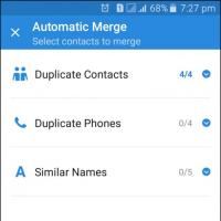 Simple Tips for Combining Duplicate Contacts on Android Tie Android Contacts
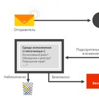 About Windows Update From Wannacry Encrypter Virus
 Hot browser keys
 New Mac Mini turned out to be five times more powerful than the predecessor
 Smartphones - Grenades: Why gadgets explode and how to avoid it