Download the cad program. CAD, CAM, CAE systems. Classification by the nature of the basic subsystem
CAD systems are used to carry out a variety of design procedures involving computer technology... Also, with the help of such software, a technological one is created for individual buildings, products or structures. Modern CAD systems are used in a wide variety of areas of modern human activity, and almost each has its own unique type of such utilities.
What it is?
Oftentimes, the abbreviation CAD is considered to be the standard English equivalent of the term CAD, but in reality this is not entirely true. CAD systems cannot be regarded as a full-fledged analogue of CAD systems as an organizational and technical system, since GOST gives this phrase in the form of a standardized English equivalent of the term "computer-aided design". Thus, the term CAD is translated into English more as CAE system, but a number of foreign sources indicate that the term CAE is a generalized concept that includes the use of any computer technology in engineering, including also CAM and CAD.
Why is this needed?
CAD systems are used primarily to maximize the efficiency and productivity of engineers through full design automation and further preproduction. Thus, due to their use, the following advantages are achieved:
- the design time is significantly reduced;
- the amount of labor required for planning and design is reduced;
- the total cost of manufacturing and design is significantly reduced, which directly affects the operating costs;
- an increase in the technical and economic level, as well as the quality of the results of the design work carried out;
- reducing the costs required for testing and full-scale modeling.
As input data, modern CAD systems use various technical knowledge of experts who are engaged in clarifying the results, introducing various design requirements, checking the resulting design, modifying it, and many other things.
The implementation of the computer-aided design system is carried out as a complex of applied utilities, with the help of which design is provided, as well as further drawing and three-dimensional modeling of structures or volumetric and flat parts.
In the majority of cases, CAD-systems include modules for modeling three-dimensional structures, as well as the design of drawings and various design text documentation.
They are classified mainly according to several parameters:
- the type and type of the object in question;
- the level of automation of the design procedure;
- the complexity of the object being created;
- the complexity of the automation process;
- the number of documents used;
- the nature of the documents used;
- the total number of levels that will be present in the structure of technical support.
Special purpose

Depending on what the tasks of CAD systems are being implemented, they are divided into several groups:
- Automation of three-dimensional or two-dimensional geometric design, as well as the creation of various technological or design documentation.
- Design and further creation of drawings.
- Geometric modeling.
- Automation of various engineering calculations, carrying out dynamic modeling, as well as analysis and simulation of physical processes, followed by verification and optimization of products.
- A subclass of CAE tools used for computer analysis.
- Means intended for the technological preparation of the production process of various products, which allows for the automation of the programming procedure and further control of equipment with GAPS or CNC.
- Tools designed to automate planning processes for various technological processes used at the junction of CAM and CAD systems.
Most computer-aided design systems can combine the solution of various tasks that relate to different aspects of design - this is an integrated or integrated computer-aided design (CAD) system.
Generally accepted international classification
The modern classification divides them into several categories:
- drawing-oriented systems, which first appeared in the seventies of the last century, but can still be used in some situations;
- systems that create three-dimensional electronic models of objects, due to which it becomes possible to solve various problems related to modeling up to the production procedure;
- systems that support the concept of a complete electronic description of an object.
The latter type is a technology that ensures the development and subsequent support of an information electronic model throughout its entire life cycle, including conceptual and detailed design, full-fledged marketing, production, technological preparation, operation, as well as disposal and repair.
In modern technical and educational literature, as well as various state standards, the abbreviation CAD is interpreted as "Computer-aided design system", but at the same time the concept of "Design work automation system" corresponds most closely here, but it is more difficult to perceive, therefore, it occurs an order of magnitude less often ... It often happens that, while designing in CAD systems, you may notice an incorrect interpretation of "Automatic design system", although in fact it is inherently erroneous. Do not forget that the concept of "automatic" fully envisages independent work systems without the need for any human participation, while CAD still requires the execution of some tasks by the person himself, and full automation refers only to individual procedures and operations.
Also not entirely correct is such a concept as "Computer-aided design software", as it can be called too narrowly focused. Of course on this moment CAD is considered exclusively as applied software necessary for carrying out design activities, however, in fact, in the domestic literature and various state standards, CAD is considered as a more voluminous concept, which includes not only software tools.
CAD in dentistry

The vast majority of modern dental clinics use CAD. CAD systems in dentistry are used for the production of high-quality dental prostheses, for more than ten years they have been used for the manufacture of abutments for implants, crowns and all kinds of prostheses, all of which are of excellent quality and high precision. The essence of this technology lies in the fact that initially a three-dimensional modeling of the created structure is carried out on a computer, and only then, using the design model, production is carried out on a milling unit.
Thus, dentists receive many benefits through the use of CAD technology in their work. CAD systems in dentistry are most often used in the following ways:
- first, the doctor takes an impression, which is then sent to the laboratory;
- after delivery, the impression is placed in a specialized scanner that creates a model of the future product;
- the CAD system comes into play: the 3D model turns into a specialized file that will serve as a data source for the milling unit;
- using the resulting file, on the milling unit, the frame is produced from a special workpiece made of zirconium oxide;
- in the end, the resulting frame is carefully covered with a ceramic mass and baked.
CAD / CAM systems in dentistry allow the production of zirconium dioxide crowns, which differ from metal-containing products in a number of advantages. By themselves, these products practically do not differ in color from natural teeth, since the choice of shade is carried out even during the production of the frame. Further, the frame is carefully covered with a special ceramic mass, which has a translucent and translucent structure, and also includes a fairly wide range of colors in its palette, which makes it possible to make crowns similar to natural teeth.
By itself, it is highly biocompatible, even when compared with precious metals, and is a hypoallergenic material, which has been confirmed in the course of a number of scientific clinical studies. However, in fact, crowns based on a zirconium oxide framework are far from the only type of product for the manufacture of which CAD / CAM systems are used. A CNC machine based on these technologies allows you to make:
- various bridges;
- customized abutments.
In addition to the already mentioned zirconium dioxide, a wide variety of materials can be used in the manufacturing process, including plastic, wax, cobalt and titanium, chromium.
What are the benefits?
These technologies provide such advantages as:
- the highest possible manufacturing accuracy with minor deviations;
- full automation of production processes, which almost completely eliminates the likelihood of errors;
- the ability to use a variety of materials;
- the ability to carry out procedures for modeling and production of products in different places;
- limiting productivity of any ongoing processes.
CAD in mechanical engineering

The CAD system (T-FLEX CAD and others) has found a fairly widespread use in the field of mechanical engineering, which differs in three levels - lower, middle and upper. This division appeared at the turn of the eighties and nineties of the last century.
The lower level includes CAD / CAM / CAE systems with low cost, which are mainly focused on 2D graphics, that is, they are mainly aimed at providing automation of drawing work. As light CAD systems, personal computers were used, which already at that time were significantly inferior in functionality to full-fledged workstations.
Top-level systems, or, as they are also called, heavy CAD systems, were developed in order to be used on all kinds of mainframes or workstations. Such systems turned out to be much more versatile, but at the same time had a rather high cost, focusing mainly on surface and solid modeling. The design of various drawing documentation in them is often carried out through the preliminary development of special geometric three-dimensional models. After that, systems in which the 3D modeling function was limited exclusively to solid models, that is, occupying an intermediate position between heavy and light, received their own, average level.
Today, the development of CAD has already led to the fact that in most middle-level systems, special tools for surface modeling began to appear, and the functions available for use in personal computers have also become acceptable for modern upper-level systems. Due to this, even the principles by which the distinction between medium and heavy systems was previously carried out has changed. Modern CAD systems of a heavy level are now called CAE / CAD / CAM / PDM, that is, those that simultaneously include such features as:
- technological and engineering design;
- engineering analysis;
- project information management;
- extended set of special software modules.
Unlike them, modern systems the middle level is usually called mainstream, mid-range or simply serial.
Systems of the same level can be called by functionality approximately equal, since some new achievements appearing in a certain software and methodological complex will be implemented in new versions of others in the near future. In CAD of large companies, it is quite common to combine several systems at the same time. different levels... This is often due to the fact that almost all design procedures can be carried out on CAD systems of the middle and lower levels, and besides that, heavy ones are too expensive. It is for this reason that enterprises buy licenses for top-level programs in a rather limited number, and the vast majority of modern client bases are provided at the expense of the lower and middle tiers.
At the same time, it often happens that CAD / CAE systems can have certain problems in terms of exchanging information with each other, but such troubles are solved through the use of special formats and languages adopted in CALS technologies, although to ensure undistorted transmission of geometric data through intermediate unified languages have some complexities to overcome.
Structure

Like any other complex system, CAD includes several subsystems that can be design or maintenance.
The former are directly involved in the implementation of various design work. As an example of these, one can cite subsystems for three-dimensional geometric modeling of all kinds of mechanical objects, circuit analysis, creation of design documentation, or tracing of PCB connections.
Service subsystems are intended to ensure the normal performance of the designers, and their combination is quite often among specialists called the CAD system environment. As typical service subsystems, design data management bases, various subsystems for the development and subsequent maintenance of CASE software are often used, as well as training ones designed to facilitate the users' mastering of technologies implemented in CAD.
Structuring in various aspects allowed the emergence of types of CAD software, of which there are only seven today:
- technical, which includes various;
- mathematical, combining all kinds of mathematical methods, algorithms and models;
- software, which is computer programs CAD;
- informational, which includes databases, management systems for these bases, as well as many other information used in the design process;
- linguistic, expressed in the form of communication languages between computers and designers, languages for data exchange between CAD hardware and programming languages;
- methodical, which includes all kinds of design technologies;
- organizational, executed in the form of job descriptions, staffing tables and other documentation, with the help of which regulation of the work of design enterprises is carried out.
It is worth noting that the entire set of information that is used in the design process is called by specialists the CAD information fund. A database is an ordered collection of information, which reflects various characteristics of objects and their relationship in a specific database.Access to the database for studying, recording and subsequent correction of data is carried out through the DBMS, and the set of DBMS and DB is usually called BND, that is, a data bank.
Classification

CAD / CAM design systems are classified according to a number of characteristics, such as application, purpose, scale (how comprehensively the tasks are solved), as well as the nature of the underlying subsystem.
In terms of applications, the following CAD groups should be distinguished among the most popular and representative ones:
- used in the field of general mechanical engineering (due to which they are usually called mechanical engineering);
- used in the field of radio electronics;
- used in the field of construction and architecture.
Apart from this, there are also enough a large number of specialized systems or allocated in the listed groups, or representing a completely independent branch of the classification. A good example is the CAD of large integrated circuits, electric cars, aircraft and a whole series of others.
In terms of scale, individual software and methodological complexes differ, including a complex for checking the strength of various mechanical products according to the finite element method or a complex for checking electronic circuits, as well as systems with a unique architecture of not only software, but also hardware.
Basic subsystem

There are the following types of CAD:
- Based on the subsystem of geometric modeling and computer graphics. Such CAD systems are mainly focused on various applications in which design acts as the main design procedure, that is, a clear definition of spatial forms, as well as the mutual location of objects. That is why this group includes many CAD systems from the field of mechanical engineering, based on the graphics cores. Nowadays, it is quite common to use unified graphics cores.
- Based on DBMS. They are mainly guided by those applications in which it is possible, by performing relatively simple mathematical calculations, to process a fairly large amount of information. They are often found in technical and economic applications, such as the design of business plans, but at the same time they are often used in the design process of large objects like control panels in automatic systems.
In addition, there are also complex CAD systems, which include subsystems of all previous types. Typical examples of such complex systems are software, which is actively used in modern mechanical engineering, or CAD LSI. The latter includes a DBMS and various subsystems for designing components, functional and logical circuits, crystal topology, as well as tests for analyzing the suitability of manufactured products. In order to ensure the normal management of such complex programs, it is customary to use specialized system environments.
CAD-programs (computer aided design) - system complexes for design, with the help of which they automate tasks at different stages of manufacturing industrial products (design, pre-production). In the Russian-language abbreviation - CAD (computer-aided design system).
All CAD-systems, regardless of terminology, are designed to optimize the work of the engineering staff of the enterprise. If applied correctly, appropriately, they increase the productivity of individual groups of employees. And this leads to an increase in the overall performance of the staff as a whole.
CAD systems deployed at the enterprise allow solving the following tasks:
- to reduce the labor intensity of individual operations and processes, which means to reduce the time and costs for the development and manufacture of products;
- reduce the time spent on preparing projects - with these systems, design is brought to a fundamentally different level;
- to increase the accuracy of manufacturing products without losses in speed (production efficiency even increases);
- reduce the costs that are necessary to maintain the engineering staff (which reduces the cost of the finished product);
- improve the quality of design - CAD programs bring it to a new technical and economic stage;
- reduce the cost of sample modeling and testing.
CAD - complete solutions. They can be software, technical, and others. With the help of CAD, they automate the preparation of design and construction documents within the enterprise, unify design, optimize the process of making management decisions (by expanding information support), and solve other problems.
Versatility and free integration with SAP solutions
Due to their high efficiency and product flexibility, the systems are used in various fields - from dentistry and medical prosthetics to mechanical engineering. Today CAD programs are software that is freely integrated into SAP systems, they are compatible with any of their solutions. Using special buses, you can combine CAD with PLM or CAM systems (computer aided manufacturing). The latter, designed to work with CNC machines, create algorithms for the numerical program control, open up opportunities for the manufacture of high-quality complex-profile products in a shorter period of time.
CAD software solutions also support:
- top-level systems - CAD / CAM Unigraphics;
- complexes at the middle level - Solid Edge;
- lower-level systems - AutoCAD and others.
The programs integrate with Pro / Engineer, SolidWorks, TeamCenter, Inventor, and other products. They are easy to learn, they have a "user-friendly" interface, wide functionality (you can customize them so that they meet the individual requirements of the customer and the specifics of the business). CAD systems support concurrent design technologies. With them, you can freely use the methods of variant optimization, mathematical modeling. Another important plus is that the price of the product is flexible. It is determined by the functionality that is selected for a specific customer, his needs, tasks, opportunities.
ASAP Consulting offers services for the development of optimized design and manufacturing solutions that use advanced automation tools. We will select CAM, CAD solutions for specific task, we will help to deploy products at the enterprise, we will advise on all emerging issues.
From the editorial site: We are publishing an abridged translation of Curt Moreno's article "Free CAD Software for Mobile Devices", which was published a few days ago. The author positions himself as a freelance writer, professional AutoCAD specialist, working with this system since 1990, as well as a regular speaker and teacher at Autodesk University.
In a rather lengthy introduction, Kurt Moreno recalls the explosive spread of mobile devices and cites an authoritative forecast: this year the number of such devices will exceed the population of the Earth. The author then explains that the penetration of mobility has not bypassed the CAD industry and provides examples of applications already observed.
It further clarifies that mobile systems should be distinguished from full-scale CAD systems that run on traditional laptop operating systems. Kurt Moreno reports that in the comparative review only those CAD applications are considered that:
- are free,
- mainly used for viewing and editing CAD files,
- written for Android and / or iOS,
- downloaded from official sites like Apple App Store or Google play Store
- can be operated with fingers using the touchscreen interface
- work through mobile telephone networks or Wi-Fi.
Finally, Kurt Moreno reports that he selected seven systems available on Google for review. Play Store and the Apple App Store, which have a fairly complete set of characteristics and are created by well-known companies. When testing selected systems, the author was guided by the following criteria, grouped into four categories (columns in the table below).
1. Interface. To what extent is the user interface natural and user-friendly?
2. A set of tools. Is it provided full set viewers and editing tools (if editing is provided in this annex)? Does the application provide only generally accepted basic features, or are there any other additional features?
3. Opportunities for teamwork. Does the application provide mechanisms for easy file sharing and / or synchronous / asynchronous collaboration capabilities? How easy is it to import and export drawings?
4. Simplicity of work. Is the app designed to be easy to use for both newbie and veteran? Does it enable you to achieve reasonably high user productivity?
It is noted that the breadth of the set of file formats has not been estimated as many systems were developed for specific CAD users.

AutoCAD 360 v2.2 (Android)
Mobile editor. Level A.Advantages: works with standard DWG files, generates and mails PDF and DWG files, provides an excellent touch interface, includes online storage.
Disadvantages: Allows files no more than 10 MB in size, it is less controllable with a stylus than with fingers.
Price: Free
Autodesk, www.autodesk.com
AutoCAD 360 is available for both Android and iOS. Installing the system, loading files from desktop computer and creating new files (in the Pro and Pro Plus versions are extremely simple). Though AutoCAD interface 360 is not much like the interface of desktop versions of AutoCAD, it is very intuitive and easy to learn. The app ran smoothly and responded quickly to finger control.

AutoCAD 360 allows users to open a variety of file formats and use the basic CAD functionality that is available in the toolbar at the bottom.

AutoCAD 360 Annotation Toolbar
Free AutoCAD 360 is a well-developed mobile CAD application that provides the ability to open and view a variety of file types including DWG, DXF, PDF, and JPG, and also allows users to annotate them. There are also model analysis tools such as distance and area calculations, coordinate support, basic layer functionality. Users can change unit types and save as PDF or DWF, and then automatically send the resulting results to colleagues on e-mail. Free version supports PDF and DWF files, but file size is limited to 10 MB. Users can view and edit files located in the included 5 GB file storage.
AutoCAD 360 Pro and Pro Plus are extensions of AutoCAD 360 functionality with added drafting capabilities, model analysis tools, tools for managing layers and saving as DWG. Users gain access to the block library, object properties and other functions. Cloud file storage increased to 25 GB and 100 GB, and maximum dimensions files up to 30 and 40 MB, respectively. Price for Pro version is $ 4.99 per month or $ 49.99 per year, while Pro Plus costs $ 99.99 per year.
Navigator Mobile v4.00.01 (iOS)
Mobile CAD viewer. Level: A-Advantages: a reliable tool for working with construction data, virtual display of construction projects.
Disadvantages: Implemented only for iOS, no functions for annotating or annotating;
Price: Free
Bentley Systems, www.bentley.com
Probably the Bentley Navigator Mobile is just what the architectural and construction professionals need. More than a simple CAD viewer, this program is a powerful tool for field work with construction information.

Object properties window in Navigator Mobile can compete with many desktop applications
Object data management functionality is made in the most robust way we've seen in mobile solutions and can easily compete with many desktop applications. Accessing, modifying, and creating model views is intuitive. Navigation in the 3D view is easy to operate and responds quickly to standard multi-touch input.
While Navigator Mobile does not support DWG or DGN files, it uses so-called i-models, which can contain information from any AEC application. Users publish the i-model using free plugins that can be downloaded from http://www.Bentley.com/iWare, or any Bentley product, and accessed through ProjectWise Explorer Mobile or Field Supervisor.
CadFaster Collaborate v2.0.3 (iOS)
Mobile CAD Viewer and Collaboration ToolLevel: B
Benefits: Combined model viewer and collaboration tool; the ability to share screens in real time.
Disadvantages: Requires expensive desktop plugins, no support for standard formats, implementation for iOS only.
Price: Free plus the cost of desktop plugins.
CadFaster, www.cadfaster.com
CadFaster Collaborate is a mobile CAD viewer designed for the 3D AEC and MCAD markets, but in general it is especially good as a collaboration tool. Users can view and comment on BIM models, including through online sharing of their screen. And all this without any CAD on a PC or iPad. CadFaster uses a desktop CAD plugin for this, which exports either EXE files or iPad compatible files.


Left: The CadFaster file directory interface allows you to quickly find your current drawing.
Right: CadFaster offers great opportunities for real-time collaboration.
One of the disadvantages of the CadFaster is its high price tag. While CadFaster for mobile is free, desktop plugin licenses range from $ 189 to $ 389 for an annual subscription. Another problem is the EXE format for files, as many IT departments consider them to be potentially dangerous.
However, CadFaster should soon be replaced by MyCadbox 2.0, which will probably eliminate the noted drawbacks.
cadTouch v5.0.0 (Android)
Mobile CAD EditorLevel: A-
Advantages: wide range of tools, DWG, blocks, raster mode support.
Disadvantages: only DWG / DXF is supported; 3D is still in beta status, there is no access to the camera.
Price: Free
cadTouch Software, www.cadtouch.com
CadTouch is a free mobile CAD editor that has a lot to offer the advanced CAD user. It is available for Android and iOS.

The cadTouch toolbars are very easy to use.

The free version of cadTouch comes with over 20 blocks in its library.
Viewing drawings is very intuitive, with support for multi-touch interfaces. The free version supports standard DWG and DXF formats, as well as PDF and JPG.
CadTouch Pro ($ 19.99) resembles the free version in functionality and appearance. However, it unlocks export features that include DWG, DXF, PDF, and PNG formats.
TurboViewer v1.5.0 (Android)
Mobile CAD ViewerLevel: B-
Benefits: Opens native DWG / DXF files, easily customizable view modes.
Disadvantages: Non-intuitive controls; 3D rotation is difficult.
Price: Free
IMSI / Design, www.imsidesign.com
The iOS version provides annotation functionality, but the Android version of TurboViewer analyzed for this article does not. (They are expected to be available in late August 2014.) The application was quite responsive to requests and it was fairly easy to configure 2D and 3D views.

TurboViewer 2D

TurboViewer in 3D mode
TurboViewer allows you to view various file types and includes DWG / DXF support. The TurboViewer Pro version ($ 19.99) adds viewers such as x-ray with transparency levels, a custom perspective view and materials. It also supports tools for managing layers.
eDrawings Viewer v2.0.1 (Android)
Mobile CAD ViewerLevel: A-
Benefits: Opens a wide range of 2D and 3D file formats.
Disadvantages: No markup tools in free version; lack of visual style control.
Price: Free
Dassault Systèmes SolidWorks, www.solidworks.com
Mechanical CAD professionals are unlikely to find anything better than SolidWorks' eDrawings Viewer. In the category of mobile viewers for the engineering industry, eDrawings Viewer looks great.
The application is easy and simple to install, it is responsive to both file opening and touch control, it supports SolidWorks files and native DXF and DWG formats. The system performed well, but it didn’t infrequently break during testing on the iPad 2.

Output and Co-Editing Options in the eDrawings Viewer

The eDrawings Viewer provides an exploded view of an assembly
The app is available as a free and professional version for Android and iOS. The free version provides multi-component viewing of mechanical assemblies with excellent eDrawing rendering, animation, and assembly exploding functionality.
The Pro version can be purchased for $ 7.99, which enables dynamic sections.
ZWCAD Touch v1.3.0 (Android)
Mobile CAD EditorLevel: B
Advantages: a very complete set of tools, very similar to a desktop CAD system, the ability to voice comments.
Disadvantages: limited set of supported formats, no functionality for defining object properties
Price: Free
ZWSOFT, www.zwsoft.com
Desktop CAD users may find it difficult to migrate from conventional user interface to more modern touch interfaces. Luckily for them, there is ZWCAD Touch from ZWSOFT, which will definitely hook many users with a "desktop" experience. This mobile CAD editor is quite functional and available for Android and iOS.

ZWCAD Touch offers many of the tools available in other desktop CAD programs.

The ZWCAD Touch 2D interface offers well-known markup capabilities.
ZWCAD Touch responds fairly quickly to multi-touch input for zooming or rotating. The ability to save the model is limited to the DWG format.
The main difference between ZWCAD Touch is its ability to save and play back voice memos attached to drawings, a functionality that will clearly be in demand by those who work in the field with busy hands.
The table presented in this material is an ordered list of manufacturers of ready-made software solutions in the field of systems engineering, development and industrial design.
Peculiarities
Along with the use of automation systems for engineering calculations and CAE analysis in the given time as a rule, computer-aided design (CAD) systems are used. Information from CAD systems goes to CAM (Computer-aided manufacturing). It should be noted that the English term "CAD" in relation to industrial systems has a narrower interpretation than the Russian term "CAD", since the concept of "CAD" includes CAD, CAM, and CAE. Among all information technologies, design automation takes a special place. First of all, design automation is a synthetic discipline, since it includes various modern information Technology... So, for example, the technical support of CAD is based on the operation of computer networks and telecommunication technologies, and CAD also practices the use of personal computers and workstations. Speaking about the mathematical support of CAD, it should be noted the variety of methods used: computational mathematics, mathematical programming, statistics, discrete mathematics, artificial intelligence... CAD software systems can be compared with some of the most complex modern software systems, which are based on such operating systems as Windows, Unix, and programming languages such as C ++ and Java, as well as modern CASE technologies. Almost every development engineer should have knowledge of the basics of design automation and be able to work with CAD tools. Since all design departments, offices and design bureaus are equipped with computers, the work of a designer with such a tool as a conventional drawing board or calculations using a slide rule have become irrelevant. Consequently, enterprises that work without CAD or use it to a small extent become uncompetitive, since they spend much more time and money on design.
CAD types
- CAD software (MO) - this type implies the combination of mathematical methods, models and algorithms in order to perform design)
- Linguistic support of CAD (LO) - this support is an expression of communication languages between designers and computers, data exchange languages and programming languages between CAD technical means;
- CAD technical support (TO) - this includes peripheral devices, computers, communication lines, data processing and output, etc .;
- CAD information support (IO) - consists of databases (DB), database management systems (DBMS) and other data that are used in design;
- CAD software (SW) is, first of all, CAD computer programs;
- Methodological support (MetO) - includes various kinds of design techniques;
- Organizational support (OO) - represented by staffing tables, job descriptions and other documents that define the work of the project company.
CAD structure
As one of the complex systems, CAD consists of two subsystems: design and maintenance. Design procedures are performed by design subsystems. Subsystems for geometric three-dimensional modeling of mechanical objects are a prime example of designing subsystems. With the help of service subsystems, the functioning of the design subsystems is carried out, their unity is usually called the system environment or the CAD shell. Typical service subsystems are considered to be design process management (DesPM - Design Process Management), design data management (PDM - Product Data Management). Dialogue subsystem (DP); DBMS; instrumental subsystem; monitor - providing interaction of all subsystems and control of their execution - these are the service subsystems of the software. The dialog subsystem of the software enables the interactive interaction of the CAD user with the control and design subsystems of the software, as well as the preparation and correction of the initial data, familiarization with the results of the design subsystems operating in batch mode.
The structure of a CAD software is determined by the following factors:
- aspects and level of descriptions created with the help of software, designed objects and subject area;
- the degree of automation of specific project operations and procedures;
- resources provided for software development;
- architecture and composition technical means, mode of operation.
CAD classification
CAD is classified according to the following principles: purpose, application, scale and nature of the underlying subsystem. According to their intended purpose, CAD systems or CAD subsystems are distinguished, which provide various aspects of design. Thus, CAE / CAD / CAM systems appear as part of MCAD:
- CAD-F or CAE (Computer Aided Engineering) systems. This refers to CAD for functional design.
- CAD-K - design CAD systems for general mechanical engineering, most often they are called simply CAD systems;
- CAD-T - technological CAD systems for general mechanical engineering - ASTPP (automated systems for technological preparation of production) or CAM systems (Computer Aided Manufacturing).
By applications, the most important and widely used are the following CAD groups:
- Mechanical CAD or MCAD (Mechanical CAD) systems are CAD systems for applications in the general mechanical engineering industries.
- ECAD (Electronic CAD) or EDA (Electronic Design Automation) systems - CAD for radio electronics.
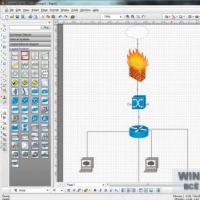
- CAD for architecture and construction.
In addition, there are a large number of more specialized CAD systems, either allocated in certain groups, or being an independent branch in the classification. These are such systems as: BIS -SAPR (large integrated circuits); CAD of aircraft and CAD of electrical machines. By scale, independent software-methodical complexes (PMK) CAD are determined:
- Complex for the analysis of the strength of mechanical products in accordance with the finite element method (FEM)
- Electronic circuit analysis complex;
- PMK systems;
- Systems with unique software and hardware architectures.
Classification by the nature of the basic subsystem
- CAD systems that target applications where main procedure design is design, that is, the definition of spatial forms and the relative position of objects. It is a CAD system based on computer graphics and mathematical modeling. This group of systems includes most of the graphic CAD kernels in the field of mechanical engineering.
- CAD systems focused on applications in which large amounts of data are processed with fairly simple mathematical calculations. It is a DBMS-based CAD system. CAD data are mainly found in technical and economic applications, for example, in the process of designing business plans, objects like control panels in automation systems.
- Complex (integrated) CAD systems, which include a set of previous types of subsystems. Typical examples of complex CAD systems are CAE / CAD / CAM systems in mechanical engineering or CAD LSI systems. Thus, the DBMS and subsystems for the design of components, fundamental, logical and functional diagrams, crystal topology, tests to verify the suitability of products is part of CAD BIS. In order to manage such complex systems, specialized system environments are used.
- CAD based on a certain application package... In fact, these are freely used software and methodological complexes, such as a complex for simulation of production processes, a complex for the synthesis and analysis of automatic control systems, a complex for calculating strength by the finite element method, etc. As a rule, CAD data refer to CAE systems. For example, logical design programs based on the VHDL language, mathematical packages such as MathCAD.
CAD development
One of the key themes of CAD development is "cloud" computing: remote work with data hosted on remote servers, with various devices with Internet access. Today, clouds have made very significant progress in the segment of lightweight applications and services - mainly in the consumer sector. There are two possible integration options. In the first case, the entire infrastructure of engineering services is transferred to the cloud, and, accordingly, the need for engineering software installed at the workplace disappears altogether. In the second case, the designer still has a graphical work station with installed CAD, but at the same time he gets from it access to various cloud services, thanks to which it is possible to solve problems that require very significant resources (for example, to carry out strength analysis). It is possible to carry out cloud interaction in two ways: publicly, when access to the server located at the provider is open via the Internet, and privately, when the server is located in the enterprise and calls to it occur over a closed local network... In Russia, the development of clouds in the field of CAD is constrained by the need to maintain excessive secrecy in many projects. Therefore, it is most likely that private clouds will become the main driver of the market in the near future. The clouds are not only about new technologies, but also the opportunity to experiment with new business models.
The next major trend is alternative operating systems. Five years ago, when there was talk of an alternative to Microsoft Windows, it was usually Linux. This topic is still relevant today: the domestic national software platform, most likely, will be based on the Linux kernel; there is a growing interest in this OS in the field of education and in government agencies (there are examples of a successful transition). However, now we can already talk about a significant potential operating system Google Chrome OS. And here the mentioned trend merges with the cloud trend - Google OS, as you know, does not imply the installation of applications on a local computer.
An important role in the promotion of this OS is played by the trend towards a decrease in the market share of the PC. Obviously, if you move most of the cumbersome and complex computing to the clouds, your hardware requirements will be reduced and you will be able to work on any device. For example, on tablets. As a result, CAD developers will have to either develop platform-independent solutions (cloud version), or make them multi-platform.
The next topic is hardware. Here again, everything is determined by the dissatisfaction of the market with the decision of the monopolist - the classic architecture of Intel (the pace of its development). In this regard, there is a clear trend towards the development of the ARM architecture. It is now supported by several manufacturers, among which one of the most active is Nvidia (Nvidia). So far, this architecture is actively used only in mobile devices, but in the near future, apparently, it will be transferred to stationary PCs. This is indirectly evidenced by the fact that the future Microsoft Windows 8 OS will be able to work on the ARM architecture too (for the first time not only on Intel).
The second trend is the transfer of a significant part of the calculations from central processing unit to the graphics core. This topic relates rather to the field of parallel computing.
Another trend is the growth of the mobile market. It got the biggest speedup last year with the iPad. At first, however, it seemed that this device was purely consumer and in the corporate sector it would not be applicable. However, it turned out that it is quite suitable for solving many problems.
In the CAD sector today, many employees are mobile - working on the road, at remote construction sites, moving around the country, working from home. (All this requires a handy mobile device.)
One way or another, abroad that every employee of the engineering service will soon have a tablet, today they speak of it as a fait accompli. Attractive mobile platforms for developers have already appeared IOS Apple and Android Google, as well as a significant number of CAD applications for them.
Now it is very difficult to say whether the keyboard and mouse will leave our arsenal in ten years. But the fact is that multi-touch (finger-oriented) interfaces are clearly gaining popularity. In mobile devices, they have almost become the standard. Today it is quite clear that this interface is more than suitable for consuming information. Whether it is just as good for its creation, for working with CAD, it is still difficult to say. The technological base is still lacking for a massive transition to such interfaces. There are simply no large enough multi-touch panels on the market today with the resolution required for CAD.
The CAD market is very conservative. Even replacing one such system with another within the framework of work on one project is a rather difficult task. What can we say about a serious change in the paradigm, interfaces, generations of CAD. Therefore, this market is clearly not among the leaders in the technological race - there is development, but obviously not as fast as we would like. However, in the next decade, engineers who have grown up in the era of the Internet, new technologies and mobile devices will come to enterprises, and one way or another they will actively bring elements of their culture to the market.
CAD in construction
Business digitalization has affected all its industries. In the last decade, solutions for the design, engineering and construction of industrial facilities have boomed. From Soviet drawing boards, designers came to 3D modeling. Alexey Lebedev, CEO of AVEVA, helped to figure out what digitalization means for this segment, how to help the team work in a single space and why it has not yet been possible to finally get rid of paper media.
 Free software for working with the network
 How the password generator works
 Recording video with sound from a computer screen: software overview Copying a computer screen program
 Getting Started with Mozilla Firefox - Download and Install
 Best free hexadecimal editors (hex) Recover archives in WinRAR
 A guide to file managers for Windows
 Free program to permanently delete files File Shredder screenshots File shredder 2