Passive Filter LF Scheme. Filters on oh microcircuits. Mr. Frequency Filters on Condenser and Chokes
The electric filter is called a device for transmission electrical signalstransmitting currents in a certain frequency domain and preventing them in passing outside this area. In radio engineering and electronics, electrical filters are subdivided into passive and active. Passive filter circuits contain only passive elements: resistors, capacitors and inductors.
In the schemes of active filters, in addition to the specified elements include active products such as transistors or integral chips. The filtering properties of the device are determined by its amplitude-frequency characteristic, which is called the dependence of the gain of this device from the frequency of the signal. In some frequency range, which is called a bandwidth or transparency band, electric oscillations Transmitted by filter from entering the exit practically without attenuation. Outside the transparency band is the attenuation band or delay, within which the frequency components are weakened. Between the transparency band and the stroke of the delay is the frequency called the boundary. Due to the fact that there is a smooth transition between the transparency band and the attenuation band, the boundary is usually considered the frequency at which the signal loosening turns out to be -3 dB - that is, by voltage in √ 2 times less than in the transparency band.
It is always interesting to gain a steep transition of the amplitude-frequency characteristic between the transparency band and the attenuation strip. In passive filters, the increase in the steepness of such a transition is achieved by the complication of the scheme and the use of multi-part systems. Complex filters require bulky calculations and accurate settings. Active filters through the use of feedback are much easier and cheaper.
It is customary to divide filters into four categories depending on the location of the transparency band:
. Lower frequency filters (0 ≤ f ≤ F 0);
. Filters upper frequencies (F ≥ F 0);
. strip filters (F 01 ≤ F ≤ F 02);
. Breaking or live filters (0 ≤ F ≤ F 01 and F ≥ F 02).
Here f - the frequency of signals passing through the filter; F 0-border frequency; F 01 - lower boundary frequency; F 02 - upper boundary frequency. Thus, the low-pass filter Nponycks the components of the signal whose frequency is less than the boundary frequency; The upper frequency filter passes the components of the signal whose frequency is larger than the boundary frequency; The strip filter passes the components of the signal whose frequency is between the lower boundary frequency F 01 and the upper boundary frequency F 02; Finally, the actor filter loosens the signals whose frequency is between the bottom boundary F 01 and the upper boundary F 02 frequencies. There are also more complex special-purpose filters, such as a comb filter used in color television, passing a lot of narrow strips and weaves between them.
Electrical filters are widely used in electrical engineering, radio engineering and electronics. So at the output of the rectifiers, the low-pass filter is used, passing only the constant component of the straightened current and weakening the passage of ripples. In the radio receivers, strip filters are widely used, which allow you to highlight from received antenna signals of multiple radio stations only one, the frequency band of which is in the filter transparency band.
Another division of all filters into two categories is adopted: the filters, the scheme of which contains inductors, and filters without inductors, RC filters or resistor-condenser filters.
Active resistor-condenser filters have a huge advantage over their passive counterparts, especially at frequencies below 10 kHz. Passive filters for low frequencies Must contain high inductance coils and large capacitance capacitors. Therefore, they are obtained bulky, expensive, and their characteristics are far from perfect.
A large inductance is achieved due to a large number of turns of the coil and the use of the ferromagnetic core. This deprives its properties of pure inductance, since the long wire of the multi-loving coil has noticeable resistance, and the ferromagnetic core is affected by the temperature of its magnetic properties. The need to use a large container forces the use of capacitors with poor stability, such as electrolytic. Active filters are largely devoid of these disadvantages.
Differential and integrator schemes built using operating amplifiers are simple active filters. When the schema elements are selected, in a specific frequency dependence, the differentiation becomes the upper frequency filter, and the integrator is the low-pass filter. Next, examples of other more complex and most universal filters will be considered. A large number of Others possible schemes Active filters together with their detailed mathematical analysis can be found in different textbooks and benefits.

Lower frequency filters
If you combine the inverting amplifier circuit with the integrator scheme, the first-frequency filter circuit is formed, which is shown on fig. one.
Fig. one.
This filter is an inverting amplifier with a permanent gain in transparency band direct current to the boundary frequency F 0. It can be seen that within the transparency band, until the capacitive resistance of the capacitor is quite large, the coincishability coefficient coincides with the gain of the inverting amplifier:
The boundary frequency of this filter is determined by the feedback circuit elements in accordance with the expression:

The amplitude-frequency characteristic - the dependence of the amplitude of the signal at the output of the device from the frequency at a constant amplitude at the input of this device - is presented on fig.2.
Fig. 2.
In the attenuation strip above the boundary frequency F 0, the amplification decreases with the intensity of 20 dB / decade (or 6 dB / octave), which means a decrease in the voltage gain coefficient of 10 times with increasing frequency is also 10 times or reduced the gain by twice each time each Frequency doubling.
If such a grinding of the amplitude-frequency response in the attenuation band is not enough, the low-frequency filter can be used, the diagram of which is shown on fig.Z..

Fig. Z.
The coefficient of amplification of the low-frequency filter of the second order is the same as in the first-order filter, due to the fact that the total resistance of the resistors in the circuit of the inverse entry, as before, is expressed by the value R1:
The boundary frequency when performing the condition R 1 C 1 \u003d 4R 2 C 2 is also expressed by the previous formula:

As for the amplitude-frequency characteristics of this filter represented on fig. four, it is characterized by an increased steep inclination, which is 12 dB / octave.

Fig. four
Thus, in the attenuation strip, with an increase in the frequency, the signal voltage at the outlet of the filter decreases four times.
Upper frequency filters
Similarly, a diagram of the upper frequency filter, which is presented on fig.5. This filter is an inverting amplifier with a constant gain in the transparency band from frequency F0 and more. In the transparency band, the gain coefficient is the same as the inverting amplifier:

Fig.5. Schematic scheme active first-order upper frequency filter
The boundary frequency F 0 at -3 dB is set in the input chain in accordance with the expression:
Steepness of inclination of the amplitude-frequency characteristic, which is presented on fig.6.In the area of \u200b\u200bthe boundary frequency is 6 dB / octave.
Fig.6.. The amplitude-frequency characteristic of the first-order upper frequency filter
As in the case of low-pass filters, you can collect an active second-order upper frequency filter in order to enhance the signal suppression in the attenuation strip. The schematic diagram of such a filter is shown on fig.7..

Fig.7.. Schematic diagram of active second-order upper frequency filter
The rolling value of the amplitude-frequency response of the second-order upper frequency filter in the boundary frequency region is 12 dB / octave, and the characteristic itself is shown on fig.8..

Fig.8.. The amplitude-frequency response of the second-order upper frequency filter
Strip filters
If you combine the active low-pass filter with the active upper frequency filter, the resulting strip filter is formed, the schematic diagram of which is given on fig.9..

Fig. nine . Schematic diagram of active strip filter
This scheme is sometimes called the selective amplifier with an in-tagrodifferentration feedback. Like amplifiers containing oscillatory contours, the strip filter also has an amplitude-frequency characteristic with a pronounced maximum at a certain frequency. It is impossible to call this frequency of the resonant, since the resonance is possible only in contours formed by inductance and capacity. In other cases, the frequency of such a maximum is commonly referred to as the frequency of quasi-conance. For the considered strip filter, the quasi-conance frequency F0 is determined by the feedback chain elements:

The amplitude-frequency characteristic of this band filter is shown on fig. 10.

Fig.10.. Amplitude-frequency characteristics of the band filter
The maximum gain at the quasi-conance frequency turns out to be:

Relative bandwidth at -3 dB:

The schematic diagram of another band filter is shown on fig. eleven.

Fig. eleven. Schematic diagram of a band filter with a double T-filter
Here, a double T-filter was included in the negative feedback circuit, formed by R2, R3, R5 resistors and CL, C2, SZ condensers.
As you know, if the following conditions are satisfied:
the amplitude-frequency characteristic of the double T-filter contains a quasi-conance, whose frequency is equal to

moreover, at the quasi-conance frequency, the double T-filter transmission coefficient is zero. Therefore, an active filter with a double T-filter included in the negative feedback circuit is a strip filter with a maximum amplitude-frequency characteristic at the quasi-conance frequency. Three such characteristics are presented on fig. 12. The characteristics differ in different resistors of the R4 resistor: the lower corresponds to R4 \u003d 100 com, the average - R4 \u003d 1 MΩ, the upper - R4 \u003d ∞.

Fig. 12. The amplitude-frequency characteristic of the active filter with a double T-filter in a negative feedback circuit
Recorder filters
The same double T-filter can be turned on not in a negative feedback circuit, as is done when creating a band filter, and in the input circuit. At the same time, an active actor filter is formed, the diagram of which is given on fig, 13..

Fig.13.. Circuit diagram of a dual filter filter
When performing the previous conditions
the amplitude-frequency characteristic of the active filter having a double T-filter in the input chain contains a quasi-conance, the frequency of which is still determined by formula (8). But at the frequency of quasi-conance, the gain coefficient of this active filter is zero. The amplitude-frequency characteristic of the active filter with a double T-filter in the input circuit is shown on fig.14.

Fig. fourteen. The amplitude-frequency characteristic of the active filter with a double T-filter in the input chain
Complex filters
Several active filters can be connected sequentially to obtain an amplitude-frequency characteristic with an increased grinding tilt. In addition, the connected sequential sections of simple filters have reduced sensitivity. This means that a slight deviation of the value of one of the components of the circuit (deviation of the resistance of the resistor or the capacitor capacity from the norm) will lead to a smaller effect on the final filter characteristic than in the case of a similar complex filter built on a single operating amplifier.

Fig. fifteen. Stage Filter Scheme
On the fig. fifteen A step filter is shown collected from three operating amplifiers. The popularity of such filters has increased dramatically after the sale is available. integrated microcircuitscontaining several operating amplifiers in one case. The advantages of this filter are low sensitivity to the deviations of the size of the components and the possibility of obtaining three outputs: the upper frequencies U Vih1, the band U of the output and the lower frequencies u divest.
The filter is composed of the DA1 summing amplifier and two DA2 integrators, DA3, which are connected in the form of a closed loop. If the scheme elements are selected according to the condition ![]()
then the boundary frequency turns out to be equal
The outputs of the upper and lower frequencies have an amplitude-frequency-frequency tilt circle, equal to 12 dB / octave, and the bandage yield has a triangular characteristic with a maximum at a frequency F 0 with Q Q-Q Q, which is determined by the resistors of the increase in the amplification of the DA1 chip.
Yuri Sadikov
moscow
The article presents the results of the work on the creation of a device, which is a set of active filters to build high-quality three-chain low-frequency amplifiers HIFI and HIEND.
In the process of preliminary studies, the total response ACH three-band amplifier, built using three second-order active filters, it turned out that this characteristic at any frequencies of filter joints has a very high non-uniformity. At the same time, it is very critical to the accuracy of the filter settings. Even with a slight mismatch, the unevenness of the total response may be 10 ... 15 dB!
The whale master releases a set of NM2116, from which you can collect a set of filters, built on the basis of two filters and subtracting the adder, not having the above disadvantages. The developed device is at least sensitive to the parameters of the cutoff frequency of individual filters and at the same time provides a high-tube total response.
The main elements of modern high-quality sound-reproducing equipment are acoustic systems (AC).
The simplest and cheap are single-band AUs, which have one loudspeaker in their composition. Such acoustic systems are not capable of high quality Work in a wide frequency range due to the use of one loudspeaker (speaker head - GG). When reproducing different frequencies, various requirements are presented to the GG. At low frequencies (LC), the speaker must have a large and rigid diffuser, low resonant frequency and have a large move (for pumping a large air volume). And at high frequencies (HF), on the contrary, it is necessary to have a small light but solid diffuser with a small course. All these characteristics are almost impossible to combine in one loudspeaker (despite numerous attempts), so a single loudspeaker has high frequency non-uniformity. In addition, in broadband loudspeakers there is an intermodulation effect, which manifests itself in modulation of high-frequency components sound signal low-frequency. As a result, the sound picture is broken. The traditional solution of this problem is the separation of the reproduced frequency range on the subbands and the construction acoustic systems On the basis of several speakers on each selected frequency subband.
Passive and active separation electric filters
To reduce the level of intermodulation distortion, electrical separation filters are installed before loudspeakers. These filters also perform the function of the distribution of the sound signal between the GG. They are calculated on certain frequency The separation outside which the filter provides the selected attenuation value expressed in decibels to octave. The steepness of the attenuation of the separation filter depends on the scheme of its construction. First order filter Providing 6 dB / Oct., second order - 12 dB / Oct, and the third order is 18 dB / Oct.. Most often, second-order filters are used in the speakers. High-order filters are applied to the speakers rarely due to the complex implementation of the exact values \u200b\u200bof the elements and the absence of the need to have higher damping values \u200b\u200bof the attenuation.
The frequency of separation of filters depends on the parameters of the applicable GG and on the properties of the hearing. Best choice The frequency of separation is in which each HG AU works within the area of \u200b\u200bthe piston effect of the diffuser. However, the AU should have many separation frequencies (respectively, GG), which significantly increases its value. It is technically substantiated that it is enough to use three-track frequency separation to be used for high-quality sound. However, in practice there are 4, 5 and even 6-strip speakers. The first (low) separation frequency is chosen in the range of 200 ... 400 Hz, and the second (middle) separation frequency in the range of 2500 ... 4000 Hz.
Traditionally, the filters are manufactured using passive L, C, R elements, and are installed directly at the output of the terminal power amplifier (mind) in the AC housing, according to Fig.1.
Fig.1. Traditional performance speakers.
However, such fulfillment has a number of shortcomings. First, to ensure the required frequency cuts, it is necessary to work with sufficiently large inductors, since it is necessary to perform two conditions simultaneously - to ensure the necessary cutoff frequency and ensure the coordination of the filter with the GG (in other words, it is impossible to reduce the inductance due to an increase in the container in the filter). The winding of inductance coils is desirable to produce on frames without the use of ferromagnets due to the essential nonlinearity of their magnetization curve. Accordingly, air coils of inductance are sufficiently bulky. In addition, there is a winding error that does not allow to provide accurately calculated cutoff frequency.
The wire that the winding of the coils is carried out, has the final ohmic resistance, which in turn leads to a decrease in the efficiency of the system as a whole and the transformation of the part of the useful power of the mind into heat. This is especially noticeable in automotive amplifiers, where the supply voltage is limited to 12 V. Therefore, for the construction of automotive stereo systems, the GG of reduced winding resistance (~ 2 ... 4 ohms) is often used. In such a system, the introduction of additional filter resistance of the order of 0.5 ohms can lead to a decrease in the output power by 30% ... 40%.
When designing high-quality amplifier Power is trying to minimize its output resistance to increase the degree of damping of the GG. The use of passive filters significantly reduces the degree of damping GH, since the additional reactive resistance of the filter is connected in series with the output of the amplifier. For a listener, this is manifested in the appearance of "bubbing" bass.
An effective solution is the use of non-passive, but active electronic filters, in which all listed disadvantages are absent. Unlike passive filters, active filters are installed until the mind is shown in Fig.2.

Fig.2. Building a sound-reproducing path using active filters.
Active filters are RC filters on operating amplifiers (OU). It is easy to build active sound frequency filters of any order and with any frequency of cut. The calculation of such filters is made on table coefficients with a predetermined type of filter, the necessary order and frequency of the cut.
The use of modern electronic components allows you to produce filters with minimal values \u200b\u200bof levels of own noise, low power consumption, dimensions and ease of execution / repetition. As a result, the use of active filters leads to an increase in the degree of damping of the GG, reduces power loss, reduces distortions and increases the efficiency of the sound producing path as a whole.
The disadvantages of such an architecture include the need to use several power amplifiers and several pairs of wires to connect acoustic systems. However, it is currently not critical. The level of modern technologies has significantly reduced the price and sizes of the mind. In addition, a lot has appeared powerful amplifiers In integral performance with excellent characteristics, even for professional use. To date, there are a number of ICs with a few mind in one building (Panasonic manufactures IC RCN311W64A-P with 6 power amplifiers specifically for building three-band stereos). In addition, the mind can be placed inside the AC and use short wires Large sections for connecting speakers, and the input signal is submitted by a thin shielded cable. However, if it is not even possible to establish the mind inside the AC, the use of stranded connecting cables does not constitute a complex problem.
Simulation and selection of the optimal structure of active filters
When building a block of active filters, it was decided to use the structure consisting of a high frequency filter (PVCH), an average frequency filter (strip filter, FSH) and low frequency filter (FNH).
This circuitry was practically implemented. A block of active Filters of LF, HF and PF was built. A three-channel adder was selected as a three-wire speaker model, providing the summation of the frequency component, according to Fig.3.

Fig.3. Model three-channel speaker with a set of active filters and FSH on PF.
When removing the frequency response of such a system, with optimally selected slice frequencies, it was expected to get linear addiction. But the results were far from the expected. At the pointing points of the filter characteristics, failures / emissions were observed depending on the ratio of the cutting frequency of the adjacent filters. As a result, the selection of the values \u200b\u200bof the cutoff frequency was not possible to lead the tramp of the frequency response system to the linear view. The nonlinearity of the passage characteristic indicates the presence of frequency distortions in the reproducible musical design. The results of the experiment are presented in Fig. 4, Fig.5 and Fig. 6. Fig.4 illustrates the pairing of FNH and PVCH at a standard level of 0.707. As can be seen from the drawing at the pairing point, the resultant response (shown in red) has a significant failure. When the characteristics are slipped, the depth and width of the failure increases, respectively. Fig.5 illustrates the pairing of FNH and PVCh in terms of 0.93 (frequency characteristics of filters). This dependence illustrates the minimally achievable non-uniformity of the flowchair, by selecting the filter cut frequencies. As can be seen from the drawing, the dependence is clearly not linear. In this case, the frequency of the filter cutter can be considered optimal for this system. With a further shift of the frequency characteristics of the filters (pairing in terms of 0.97), an emission appears in the passage of the frequency response at the dock of the filter characteristics. Such a situation is shown in Fig.6.

Fig.4. Ahh Fnch (black), Ahh FVCH (black) and passage of frequency response (red), matching in terms of 0.707.

Fig.5. Ahh FNH (black), Ahh FVCH (black) and passage of frequency response (red), matching in terms of 0.93.

Fig.6. Ahh FNH (black), Ahh FVCH (black) and passage of frequency response (red), matching in terms of 0.97 and the appearance of emission.
The main cause of the nonlinearity of the flowchart is the presence of phase distortions on the boundaries of the frequency of the filter cut.
Decide similar problem Allows the construction of the mid-frequency filter is not in the form of a strip filter, but using the subtracting adder to the OU. The characteristic of such an FSH is formed in accordance with the formula: UIC \u003d URH - URH - UR
The structure of such a system is presented in Fig.7.

Fig.7. Model of three-channel speakers with a set of active filters and FSH on the subtracting adder.
With this method, the formation of the average frequency channel disappears the need for accurate adjustment of the adjacent frequencies of the filter cut, because The mid-frequency signal is formed by subtracting from the full signal of high and low frequency filters. In addition to providing complementary frequency response, filters also have complementary FFCs, which guarantees the absence of emissions and failures in the total response of the entire system.
The range of mid-frequency link with the frequencies of the FCR1 \u003d 300 Hz and FCR2 \u003d 3000 Hz is shown in Fig. 8. The responding response is ensured by attenuation of no more than 6 dB / Oct, which, as practice shows, quite enough for practical implementation FSH and receipt high-quality sound Sch gg.

Fig.8. ACH medium frequency filter.
The passage of the transmission coefficient of such a system with FNH, PVCH and FSH on the subtracting adder is obtained linear in the entire frequency range of 20 Hz ... 20 kHz, according to fig. 9. Amplient and phase distortions are completely lacking, which provides crystal purity of the audio signal.

Fig.9. Ahh filter system with FSH on a subtracting adder.
The disadvantages of such a solution include strict requirements for the accuracy of resistor ratings R1, R2, R3 (according to fig.10, which is represented electrical circuit subtracting adder) providing balancing adder. These resistors should be used with accuracy tolerances not more than 1%. However, if there are problems with the acquisition of such resistors, the adder is required to be balanced using instead of R1, R2 trimming resistors.
The balancing of the adder is performed according to the following method. First, it is necessary to submit low-frequency oscillation to enter the filter system, much lower than the frequency of the FNH slice, for example 100 Hz. By changing the R1 value, you must set the minimum signal level at the output of the adder. Then an oscillating with a frequency of obviously served on the input of the filter system. more frequencies FVC cut, for example 15 kHz. By changing the R2 value again set the minimum signal level at the output of the adder. Setup is completed.

Fig.10. Scheme of subtracting adder.
Method for calculating active FNH and FVCH
As the theory shows the beam frequency filtering, it is necessary to use batterworth filters of no more than second or third order, providing minimal non-uniformity in the bandwidth.
The second order FNF scheme is presented in Fig. 11. Its calculation is made by the formula:

where A1 \u003d 1.4142 and B1 \u003d 1.0 are tabular coefficients, and C1 and C2 are selected from the C2 / C1 ratio greater than 4xb1 / A12, and the C2 / C1 ratio should not be selected with a lot of the right part of inequality.

Fig.11. Scheme of the FNH batterworth 2nd order.
The second-order FVC scheme is presented in Fig. 12. Its calculation is made by formulas:
where C \u003d C1 \u003d C2 (defined before the calculation), and A1 \u003d 1.4142 and B1 \u003d 1.0 are the same tabular coefficients.

Fig.12. FVCh Batterworth 2nd Order Scheme.
Specialists Master Kit developed and investigated the characteristics of such a block of filters with maximum functionality and minimal dimensions, which is essential when applying the device in everyday life. The use of a modern element base allowed us to ensure maximum quality development.
Technical characteristics of the filter block
The circuit electrical circuit of the active filter is shown in Fig. 13. The list of filter elements is given in the table.
The filter is made on four operating amplifiers. OU is combined in one case IMC MC3403 (DA2). On DA1 (LM78L09), the supply voltage stabilizer with the corresponding filtering tanks is assembled: C1, C3 in the input and C4 to exit. An artificial average point is made on the resistive divider R2, R3 and the C5 condenser.
On DA2.1, a buffer stage of the conjugation of the output and input resistance of the source of the signal and filters of the NCH, RF and SC is performed. At the OU DA2.2, the LF filter is assembled, the DA2.3 - Filter of HF. The DA2.4 OU performs the function of the shaker of the strip of the filter.
The contacts of the X3 and X4 feed the supply voltage, to the contacts x1, x2 - the input signal. Covers X5, X9 removed the filtered output signal for the HC path; With X6, X8 - HF and with X7, X10 - SC paths, respectively.
Fig.13. Scheme Electrical Principal Active Three Poland Filter

List of elements of the active three-band filter
| Position | Name | Note | Count |
| C1, C4. | 0.1 μF | Designation 104. | 2 |
| C2, C10, C11, C12, C13, C14, C15 | 0.47 μF | Designation 474. | 7 |
| C3, C5. | 220 μF / 16 V | Replacement 220 μF / 25 V | 2 |
| C6, C8. | 1000 PF | Designation 102. | 2 |
| C7. | 22 NF. | Designation 223. | 1 |
| C9. | 10 NF | Designation 103. | 1 |
| DA1 | 78L09. | 1 | |
| DA1 | MC3403. | Replacement LM324, LM2902 | 1 |
| R1 ... R3. | 10 com | 3 | |
| R8 ... R12. | 10 com | Admission no more than 1% * | 5 |
| R4 ... R6. | 39 com | 3 | |
| R7 | 75 com | - | 1 |
| DIP-14 pad | 1 | ||
| Pins connector | 2-pin | 2 | |
| Pins connector | 3-pin | 2 |
Appearance The filter is shown in Fig. 14, the printed circuit board is in Fig. 15, the location of the elements is in Fig.16.
Constructively filter is made on pCB from folgized glasskeepolite. The design provides for the installation of the board in the standard BOX-Z24A case, for this, the mounting holes along the edges of the board with a diameter of 4 and 8 mm are provided. The board in the housing is attached by two screws-screws.

Fig.14. Exterior view of the active filter.

Fig.15. Printing board of the active filter.

Fig.16. The location of the elements on the printed circuit board of the active filter.
Filter for subwoofer
Everyone wants to have their own personal home theater at home, that at the current prices for a public visit is fully justified, but not everyone is obtained. Someone is content with the purchase of cheap Chinese 2.1 columns, someone adapts for bass Soviet acoustics. And the most advanced radio amate radio amateurs make the subwoofer LF Channel itself. Moreover, the manufacturing procedure is not completely complicated. The standard subwoofer is an active Filter of the LC, which serves the signals of the right and left channels of linear output, the power amplifier on a lot of watts and a large wooden box with a low-frequency speaker.Calculation and manufacture of the case The case is pure carbonate, you can read about itother resources, power amplifier is not a problem - with a rich assortment of all sorts and. But at the entrancefilter LF for a subwoofer canal amplifier, we will stop in detail here.
As you know, the subwoofer reproduces frequencies up to 40 Hz, and is used in conjunction with small satellite loudspeakers. Subwoofers are passive and active. Passive subwoofer - It is placed in the housing housing of the head, which is connected to the general amplifier. With this method of connecting, the broadband OMPC output is fed to the subwoofer input, and its separation filter removes from the LF signal and the filtered signal for loudspeakers is supplied.
A much more efficient and common method of connecting a subwoofer using an electronic separation filter and a separate power amplifier, which allows you to separate baces from the signal supplied to the main loudspeakers in the place of the path where the signal filtering contributes much less nonlinear distortion than filtering the output signal of the power amplifier. In addition, adding a separate power amplifier for the subwoofer channel significantly increases the dynamic range and frees the amplifier of the main sch and RF channels from the additional load.Below suggest the first the simplest option Filter LF forsubwoofer. It is made as a filter for an adder on one transistor and the serious sound quality with it does not have to count. Leave it to assembling the very beginning.

But these three options with the same success have proven themselves as excellentfilters forsubwoofer and some of them are installed in my amplifiers.


These filters are installed between linear output Signal source and subwoofer power amplifier input. All of them have a small level of noise and power consumption, a wide range of supply voltages. The chips used any dual OU, for example TL062, TL072, TL082 or LM358. The passive elements are presented the usual requirements, as the details of high-quality audio cutters. On my hearing, the sound of the bottom scheme was especially elastic and dynamic, the subwoofer with this option is not even ears, but a belly :)
Specificationsfilter forsubwoofer:
- supply voltage, 12 ... 35V;
- current consumption, ma 5;
- cutting frequency, Hz 100;
- strengthening in the bandwidth, dB 6;
- flowing outside the bandwidth, dB / Oct 12.
Sabvofofer filter cards provided by Dimanslm Comrade:


Adding an active subwoofer significantly increases the dynamic range, lowers the lower boundary frequency playback improves the purity of the middle frequency sound and provides high level Volume without distortion. Removing low frequencies from the spectrum of the main signal coming into satellites allows them to sound louder and cleaner, as the Cone of the LF-head does not hesitate with a large amplitude bringing serious distortion, trying to reproduce the bass.
Classification of filters and their main characteristics
The classification of filters can be carried out according to different features, the most important of which is a sign associated with the frequency bandwidth. This feature distinguish the following types of filters:
§ lower frequencies (FNH);
§ upper frequencies (FVCH);
§ strip (PF);
§ Recorder or scolding (RF).
If the filter passes harmonics with a frequency from zero to a fixed frequency called the bottom cutoff frequency f. NSR (W NSR \u003d 2P f. NWR), relaxing all the frequencies above this frequency, then this filter refers to the FNF. If the filter passes all harmonics with frequencies, ranging from a fixed frequency called the upper cutting frequency F. WRV (W WRV \u003d 2P f. WRC), and loosens all frequencies below this frequency, then this filter refers to the FVCH. Filter that skips harmonics with a frequency ranging from some fixed bottom cutoff frequency f. NSR to the installed top frequency F. WRC, and suppresses harmonics with all other frequencies, then this filter refers to PV. Finally, if the filter presses the harmonic, only with a defined fixed frequency f. P and misses all harmonics with other frequencies, then this filter refers to the Russian Federation. The main characteristics of filters according to the definition are response and FFH. Amplitude-frequency characteristic N.(j.w) \u003d ç TO(j.w) Changes the change in the relationship of the output and the input amplitudes of harmonics depending on the change in its frequency. The phase-frequency response is determined by the function J (W), which describes the change in the output phase of the harmonic signal relative to its input value, depending on the frequency change. The corresponding cutoff frequencies are from the equation N.(W. I.) \u003d 0.707 \u003d 1 / Ö2, where w I. Sets the corresponding cutoff frequency at 0.707 or at 3 dB. According to Ahh, which is usually represented by a graph or analytically in the formula formula, in addition to the corresponding cut frequencies and other parameters can be determined. These parameters include the bandwidth D f. p, filter attenuation band D f. h and suppression band D f. PD.
Frequency range for ACH from zero to f. NWR or OT f. WRC and the above is called bandwidth. As the frequency response can not instantly fall to zero after f. NWR or on the contrary will ride from zero to f. WRC, then there is a certain frequency interval frequencies exceeding f. NWR or not exceeding f. WRC, which is called the attenuation strip (barrier) or transitional frequency interval. At the same time, the lower level of attenuation or, accordingly, the increase in the frequency response, which determines the transition site, corresponds to a certainty value A equal to, for example 0.1 (Fig. 1). Then the transitional frequency interval is determined by the solution of equations N.(W PZ. I.) \u003d a and N.(W. I.) \u003d 0.707, where the index i. Determines the corresponding cutoff frequency at the level A and 0.707. All frequencies above or respectively below w pz I. belong to the so-called, the suppression band of the corresponding filter.
An important characteristic It is cool S.(f. 1 ,f. 2) ACH filter, which is determined by the angle of inclination of Ahh (ACH) in the bar of the barrier and is analytically determined from equality
S.(f. 1 , f. 2) \u003d 20 log [ N.(f. 1) / N.(f. 2)],
where N.(f. 1) I. N.(f. 2) - the values \u200b\u200bof the frequency response, respectively, at frequencies f. 1 I. f. 2, taken within its attenuation band.
For evaluation of steepness S.(f. 1 , f. 2) SCH filter in decibels for a decade need equality f. 2 = 10 F. 1, and for its evaluation in decibels to octave - f. 2 = 2 F. 1 .
Filters depending on the circuitry execution are divided into passive and active. Active filters differ from passive filters, first of all, the presence of an active element made, for example, in the form of an operating amplifier.
In fig. 1 shows illustrative graphs of frequency characteristics indicating their main parameters and are indicative.
Figure 1.- illustrative graphs of frequency characteristics of AMC, VFC, PF
Since the frequency properties of filters, including the steepness of the frequency response, are determined by their gear ratio, then, depending on its type, the filters of the first, second and higher orders differ.
Transmission function of active FNF n.-o order has the appearance
TO(s.) \u003d K. 0 /(1 + A. 1 s + A. 2 s. 2 + .... + A n s n),
where TO 0 - the transmission coefficient on constant current.
Obviously, the order of the gear ratio is determined by the corresponding scheme of the real filter. So, for the first-order filter, the transfer function with s \u003d J.w I. TO 0 \u003d 1 is described as
TO(j.w) = 1/(1 + RC J.w)
where R.and C. The ratings of the resistor and the capacitor included in the filter circuit, and the FCH has the form J (W) \u003d - Arc TG (W / W 0), since W 0 \u003d T -1 at T \u003d RC.
From the transfer function, by simple transformations, we get achm for the first-order FNH

Performing similar actions, get ahh and ff for FVCh 1st order

j (w) \u003d p / 2- Arc TG (W / W 0).
High-order filters can be built with a cascade connection of smaller filters. For example, fourth-order filter can be created using serial connection Two second-order filters. In this case, the transfer functions are multiplied.
The second-order active filter circuits include the operational amplifier (OU) is compressed by a negative or positive feedback in the form of frequency-dependent chains. Examples of such filters are shown in Fig. 2 (A, B, B).

Figure 2. - 2-order filter diagrams on OU operating amplifiers: but - FNH; b. - FVCH; in - RF.
As follows from fig. 2 ( but) FNH 2-th order is based on a cascading compound of two RC chains, and in the first RC The chain of the capacitor is connected to the OU output and, thereby, it forms a positive feedback For OU in order to increase the filter transfer ratio f. NSR The determination of the ratings of resistors and capacitors is carried out at a given frequency f. NSR in accordance with formulas


Usually pre-set resistors R. 1 I. R. 2. Next, according to the above formulas, the ratings of capacitors are calculated, selecting the nominal nominal coming to them and, if necessary, adjust the pre-selected quotations of resistors to provide the desired frequency f. NSR Thus, calculations are performed by consistently adjusting the ratings of resistors and capacitors, in order to ensure the required frequency value f. NMR and the correspondence of the ratings of resistors and capacitors serially produced row.
If in the scheme but) Change the resistors and capacitors in some places, then as a result we obtain PVCH, the diagram of which is shown in Fig. 2 ( b.).
If you sequentially connect the FGH and PVCH with the corresponding response, then the result is PF.
In fig. Fig. 2 ( in) The scheme of the Russian Federation collected on the basis of a t-bridge formed by resistors and capacitors is represented as indicated in the scheme. In this case, the output of the repeater performed on the OU has a feedback connected according to the figure to a point located between the condenser FROM 1 and resistor R. 2. Thanks to this inclusion, Quality T.-The cost significantly increases, which leads to a narrowing of the frequency band in the neighborhood of the frequency of the Russian suppression f. 0 \u003d 1 / (2 P R. 1 C. 2).
Filters are designed for selective selection of the beneficial signal from a mixture of noise, interference and the signal itself. Filters are characterized by a bandwidth, a resonant frequency, the efficiency of excretion / weakening of the useful / interfering signal.
Filters are one of the most common and significant nodes of radio-electronic equipment. They allow:
♦ Select the necessary information from the noise signal;
♦ improve the signal / noise ratio;
♦ improve the quality of the signal.
For appointment, filters are known:
♦ High (upper) frequencies;
♦ low (lower) frequencies;
♦ strip;
♦ narrowband;
♦ broadband;
♦ Recorder (scarecrow), etc.
OU .
In fig. 38.1 shows typical low frequencies and it is suitable acc.
Consider the main types of filters made using
As is known, the transmission coefficient of the OU, on the scheme, fig. 38.2, defined as 1 + R3 / R4. To implement the standard low-pass filter, it is necessary to perform the following conditions:

Fig. 38.2. Example of practical implementation of low frequencies
C1 \u003d C2 \u003d C, R1 \u003d R2, ![]() Then
Then
the frequency of the filter cutter can be determined from an approximate ratio: DGC] \u003d 10 / s [ICF], Fig. 38.3. A similar conclusion can be obtained to calculate the high frequency filter.

By connecting the low and upper frequency filter sequentially, which can be obtained that is represented in Fig. 38.9.

Fig. 38.7. Example of the practical implementation of high frequencies

Note.
The deviation of the precisional elements of the filters from the recommended (calculated) values \u200b\u200bshould not exceed 7%. Note that for constructing the filter, the precision elements (, resistors) of equal rating included to obtain values \u200b\u200bR / 2 and 2C are in parallel.

♦ output amplifier (DA 1.2);

Cutting frequency, from ... to
Supply voltage
Table 38.1 (continued)
|
Cutting frequency, from ... to |
Supply voltage |
Strip linear filters of the 2nd (* 4th; ** 8th) order
with the program and the program: Dip case, Wideso; 2 (** 4) element in the case Table 38.2
|
Cutting frequency, from ... to |
Supply voltage |
5th order ladle filters on switchable capacitors:
dIP case, SO; 1 Element in Case Table 38.3
|
Cutting frequency, from ... to |
Supply voltage |
Cutting frequency, from ... to |
Voltage |
Note.
The DA1 comparator's threshold is set by the R4 potentiometer. The maximum sensitivity of the comparator is 10 mV. The HL1 LED indicates the presence of an outgoing signal. The R7 potentiometer establishes the upper limit of the reaction of the LED-scale control microcircuit of the DA2 by the control voltage value - from 1 to 6 V; R10 potentiometer - lower limit - from about to 5 V; VD4 protects the control inputs of the DA2 chip from overvoltages, while simultaneously stabilizing control voltages.
VD5, VD6 automatically provides a minimum difference between the upper and lower levels of control voltages on the conclusions 3 and 16 of the DA2 chips in 1 V. Diode VD3 protects the control circuit of the LED-scale from overvoltage. R11-R22 resistors are designed to match the level of signals removed from the DA2 chip outputs with CMO-logic levels.
If an outdoor analog (or digital) signal comes to the device input, then with an increase in its frequency, smooth alternate or simultaneously group switching of the indication channels (HL2-HL13) will occur. At the same time, control signals from the outputs of the DA2 chip through CMOS-inverters DD1, DD2 will arrive at the control inputs of analog CMOS keys (DA3-DA5 chips).
The bandwidth of each of the channels during installation on control inputs 3 and 16 DA2 chips of the maximum and minimum levels 6 and o b, respectively, will be for the first six channels of 400 Hz y for the remaining - 760 Hz. Thus, the first channel will skip the signals with a frequency below 400 Hz, the second - in the 400-800 Hz strip, ... the last, the 12th channel passes the frequency over 6 kHz.
Note.
The R7 and R10 potentiometer adjustment can be smoothly changed the width and boundaries of frequency channels.
HL2-HL13 dynamically indicate the number of the activated control channel.
The device consumes 60l * and with a supply voltage of 15 b and one turn of a bouncing LED.
Shustov M. A., scheme engineering. 500 devices on analog chips. - SPb.: Science and Technology, 2013. -352 p.
 Error appearance during program launch
 FRIGATE plugin for Firefox
 How to show hidden folders and files in Windows
 Ways how to make a screen on a laptop brighter or darker
 How to format a flash drive, disk protection
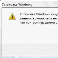 If installing Windows to this disc is not possible
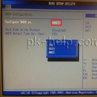 During installation of Windows "Make sure that the controller of this disc is included in the computer's BIOS menu.