Measurement of antenna parameters for kV transceiver. Three stages of antenna settings. Set up simple antennas
In the manufacture of small-sized radio devices (wearable radio stations, radio microphones, etc.), an antenna is required to obtain maximum efficiency connected directly to the output of the transmitting path. One of the criteria when adjusting the antenna is to obtain the maximum tension of the electromagnetic field in the far zone. To assess the field strength, you can collect a simple electromagnetic radiation detector, the diagram of which is shown in Fig. one.
V. Effimov, Issuntuki,
For efficient work Any transmitting radio station must be minimized by the loss of RF energy, inevitable when it is transmitted from the radio transmission device (TX) to the antenna by the feeder line. This is possible only when high quality Coordination and, therefore, in the presence of a device that allows you to control them with sufficient accuracy. In practice, the greatest distribution was the meters built according to diagrams or bridge type, or using measuring current transformers or directional couplers different designs. All of them in certain cases have both advantages and disadvantages, which is fully described in the literature [1, 2, 3,4]. Given this, it is desirable to have a fairly universal CWW meter, as well as the equivalent of the load in its composition (built into the device).
It is precisely such qualities that the universal CWW meter has a diagram of which is shown in Fig. one.
 A. Titov, Tomsk PA 7 / 8'2009 The stress wave coefficient meters (KSWN) are used to determine the quality of the coordination of individual nodes of radio engineering paths. Due to the wide development of systems cable television It is very important to know its value in each particular case. To measure the KSWN and the proposed device is intended.
The meter of undergoing power and the CWS is known that successful operation on the air largely depends on the effectiveness of the antenna of the amateur radio station. There is a wide variety of shortwave antennas. Beginner radio amateurs typically use the most simple, not requiring high costs. More experienced sets on high masts, multi-element directed antennas with remote control The position of the main petal of the focus chart. But any antenna will give good results only when it is properly configured. Substantial assistance to the radio amateler in the antenna setting will be provided by the proposed device.
 Usually in amateur structures using a CWW meter based on a directed coupler, having a switching and reflected wave and sensitivity regulator. When setting the transmitter has to produce a large number of manipulations not only with the control bodies of the P-circuit, but also the KSV meter. The device described below allows you to simplify the procedure for matching the transmitter and load.
The device (Fig. 1) allows you to measure the CWS and the power in the load in the feeders 50 or 75 ohms.
L. Nikolsky, B. Tatarko, Tver, when setting up antennas in amateurs of radio amateur practice, use bridge meters of two types: unbalanced and balanced. The first are known as KSW meters and received relatively widespread. The second in the literature is usually called antennal blocks. They are less common, although they allow you to get some additional (compared to the SW meters) information about the antenna-feeder path of the radio station, the analysis of which can facilitate its setting.
The article is written for beginners, those who are first time to set up an antenna to work on the channel you need (frequency). Who has repeatedly engaged in the antennas setting, are unlikely to find something useful for themselves in the article.
The article describes the main points of the adjustment of simple single-band antennas - automotive mortar, on a magnetic base, base 1/4 GP, 1/2 (half-gun), 5/8 (five eighth).
What you need to configure antenna
KSV-meterThe device that shows the ratio of the straight line (coming from the radio station to the antenna) and the reverse (reflected from the antenna) waves in the cable.
Indirectly, this device shows that the outlet wave resistance of the radio station is equal to the resistance of the cable, and it is equal to the antenna resistance. The fact that such wave resistance is and how it differs from the one that shows the usual tester, you can read in the article :.
The KSW meter (KSW meter) can be purchased (the price of the question is about 1000 rubles) or for a while to ask for anyone from acquaintances, who has it.
Radio station
The CSW meter does not work without a radio station.
The more "grids" is in the radio station than the broader frequency range can be rebuilt the radio station, the easier it will be to configure the antenna to the desired frequency (channel).
Having a radio station with 40 channels for 27 MHz, you can adjust the antenna, but it is very difficult, with a radio station that has 400 or 600 channels, it is much easier to do.
Roulette or ruler
It will be necessary to measure the antenna web and determine how many centimeters to shorten or extend.
In principle, you can do without a roulette or ruler and performs the setting just step by step, by slightly shortening or extending the antenna canvas.
Basic provisions when setting up antenna
Antenna must be configured at the place where it will then stand.That is, an antenna must be configured in those conditions in which it will further be operated, especially if at a distance closer than 2-3 wavelengths (wavelength \u003d 300 / frequency in MHz (for 27 MHz wavelength of approximately 11 meters)) there are some Conductive items parallel to the antenna canvas.
If it is a basic antenna, then it is already necessary to prepare a mast for it, which allows you to shoot and install an antenna, raise and lower it all for configuring and maintenance.
If it is a car antenna, then the car should be phased so that there is exactly the situation that there is exactly the situation that will be when driving on it at the time of the radio station, that is, at a distance of the order of meters 5-10 stood other cars, but on the other hand there should be no There are walls of reinforced concrete houses, garages, you can not stand inside the iron garage or hangar. At the time of measurements, the doors must be closed when setting up the car. It is not necessary to stand next to the car, the human body absorbs radio waves and thus makes losses, affects the operation of the antenna.
At a distance of 2-3 wavelengths from the antenna should not be moving conductive objects.
All device connections must be reliable.
You should not keep everything "on the weight", pressing the contacts to contact somehow, as the stripped pieces of the cable, which are about to fall out of the connector or closed.
Reliable connections are needed that the testimony of the device does not change as they do, they did not swam and were repeated. If the testimony is not repeatable, it is no longer an instrument reading, but the weather on Mars at the time of eating Snickers and focus on such indications is impossible.
How to use the KSV meter
We connect the cable to the antenna, the other end of the cable to the KSW meter, to the "Ant" connector, connect the "TRANS" KSV meter connector to the antenna connector of the radio station.Turn on the radio station and set the frequency on which we will perform the measurement of the CWS.
If there is a Switch switch SWR / PWR to translate to the SWR position.
Switch on the "FWD / REF" XV meter to the FWD position.
Click on the transfer on the radio stations and install the arrow to the end of the scale protruding from the CWW meter. We release the transfer.
Install the "FWD / REF" switch to the REF position.
Press the transmission and count on the indicator the testimony of the KSW. On most of the KSW meters, the less the arrow to deviate the shorter the shorter, if it does not deviate at all, then the KSW \u003d 1 or the device is dead. If at all frequencies, in the reference position, the arrow is not deviated, then either you instead of the antenna connected a good equivalent of the load, or the device died, but we will not be about sad.
Antenna Setup - step by step
We connect everything to measure the KSW, as mentioned above, the antenna in the working position.- We set the highest frequency on the radio station, which is capable of issuing a radio station, for example, the G channel 40 (more precisely, see the instructions for the radio station).
- Measure the CWW, moving down the frequencies of approximately 20 channels (200 kHz), remember, at what frequency (channel, grid) was a minimum of CWS and which CWS was in a minimum.
Now there are several options:
KSW everywhere large, device "scale".
Or you do not use the KSV meter or you have a break in the cable or antenna.
KSW smoothly, as the frequency decreases, falls, but we did not reach the minimum.
Your antenna is too long. Need to shorten. In shortening it is worth remembering golden Rule: "Seven times measure cut once". Shortening to join back in the history of cases is impossible, so we shorten on a little bit, for antenna Si-bi range of 27 MHz a little bit, it is about 1 centimeter, for LPD or PMR antennas of the range of 433-446MHz a little bit it is 2 millimeters.
KSV as the frequency decreases increases.
Your antenna is too short. Antenna needs to be lengthened. As far as exactly - better than 20 percent, and then crushing.
The KSW as the frequency decreases fell, at some frequency it became minimal, and then, as the frequency decreases further, it began to increase again.
This is the most frequent occasion.
It means such a behavior that everything is fine, the antenna works in the desired range, it remains only to adjust it to the desired frequency (channel).
If you have this case, it is advisable to find exactly on what channel is the minimum of CWS.
If the frequency on which was at least the CWS lower than you, then the antenna should be a little bit to shorten, literally 5 millimeters, if we are talking about the range of 27 MHz, after each shorting to watch where the minimum of the CWS is now, and shortening so far as long as the minimum CWS will not be in the required frequency.
If the frequency on which was the minimum of the KSW higher, the antenna needs to be lengthened.
What to do if the minimum CWW is in the desired frequency, but this is the minimum value is still big
This suggests that the antenna works not entirely as they conceived by the manufacturer or the rubbish antenna, however, you do not need to immediately about sad.If this is a car mortise antenna, then maybe it "lacks the masses", that is, contact with a lot of bad.
If it is a car antenna on a magnet, then it can also be "missing mass", for example, the paint layer is too thick.
Or your car antenna is located where you should not put - next to the elements of the metal trunk on the roof, next to the extra light that you hung on the trunk, you generally lived on a hood or trunk, bumper or wheels disk.
Maybe you secured the mortise antenna on the aluminum trunk's aluminum clamps, which you have on the roof, but the trunk was not aluminum and plastic or does not have reliable contact with the mass of the car, or not long and widely, which would perform the role of the mass for the antenna.
If an antenna is on a magnetic base, try searching for another place where it will "make it", try with the roof corner, in the center of the roof, from another corner.
Toki radio frequencies flow not quite since d.C.Where the tester will show excellent contact, for radio frequency it may be a "bottleneck".
If the rowing antenna, look, whether you read the place from the paint, where the contact of the mass of the antenna is attached.
If the mortise antenna you fastened on the trunk or some fasteners on the drain, try to improve contact with the mass. There were cases when the author of the article took 2 pieces of the wire 0.5mm thick without isolation, wound on the bracket on which the mortise antenna hung on the drain or trunk was fixed, threw them into different angles of the roof of the car on the waterproof and CWS with 3 decreased to 1, then There is an antenna started to work perfectly (naturally the signal on the air was also improved).
Throw extra wires, tear paint and then pour the sealant or search for other ways to improve the mass or installation point - to solve you, this is your antenna and your car.
If you do not have a car, but the basic version of the antenna, then the treatment here is actually exactly the case, namely: it may need more "masses", and maybe you need to climb an antenna design with a soldering iron.
To begin with, we are convinced that there is enough mass - the bottom of the base, it is the main opposition, the mass for the 5/8 antenna (five eighth) and 1/2 (half the wave) should be at least 1/4 of the wavelength, that is, for 27 MHz it is About 2 meters 75 centimeters. More - better; Less - it will have to lengthen the wire thrown on the roof.
Although sometimes it happens that everything is done well, and the antenna is not configured, so it was a familiar author of the article, 1/2 did not want to tune. It seems in the frequency, and the KSV is not 1 and not even 1.2 and not 1.5 - it turned out someone "climbed into the antenna" to it and cut off the coil of the coil installed inside the antenna.
Very likely what prevents your basic antenna Nearby stretched optics of your provider or mast collective antenna.
How much to cut and what is the ruler?
The dimensions of the antennas depend on the frequency linearly.
In case the antenna is full-size, then how much it needs to shorten or lengthen, to get into the desired frequency, directly depends on the ratio of the current frequency, where it resonates and the desired frequency, where we would like an antenna to resonate.
I will explain on the example:
We have a quarter, then let it be 267 centimeters, it resonates (CWS minimally) was at a frequency of 27.0 MHz (4 channel sect c), we want an antenna to earn at 27.275 MHz.
We consider the difference in frequencies:
27.0 / 27.275 = 0.9899175068744271
We multiply to this to the current length of the antenna:
267 * 0.9899175068744271 = 264.3
And we get the length that an antenna should have to earn at 27.275.
Calculate how much cut:
267 - 264 \u003d 3 cm.
But!
It is not necessary to cut at once on 3 cm. Do not forget, the antenna is not only a pin, it is also a counterweight. It affects everything.
So you can reflect the order of the first cutting - if 3 cm, or 5 mm.
Next, act step by step.
For the example above, you can cut off 1.5 cm, it is again to find the resonance, and on the basis of the result obtained, you move further.
Lastly, although it was probably necessary to write the first:
Basic rules for installing antennas
The antenna must be put not closer to one wavelength to other conductive subjects, especially those that will be parallel to the antenna.
The higher the antenna is installed, the better.
It is clear that for automotive antennas for 27 MHz, these rules are simply impossible to comply with this car antennas Compromise, for this, do not require miracles from them.
If you still have no time, there is no desire to understand the wisdom of measurement of the CWS, search for a CSW meter, customize the antenna yourself and you are in Novosibirsk, you can contact for example here:
Three stages of the antennas settings sooner or later, each radio amateur faces the need to set the antennas. Chatting on these topics with radio amateurs on the air, came to the conclusion that most of them the most important criterion for setting antenna considers the receipt of the KSV value about a unit (ideal - one or a little more!). And it is correct and ... not quite! I will explain: take a rather long coaxial cable (several lengths, and better - dozens, waves from the operating frequency), one end connect to the antenna output of the transceiver, and the other ... short! And measure the CWC (in order to safely use your transceiver, do not make output power - only to the level that provides the ability to measure the CWS!). You most likely get some kind of digit that differs from the unit (the value obtained is not much important). Then, shorten a little cable, and again make a measurement of the CWS - the value will change. So, having done several measurements, you can achieve the value of the KSV close to one. What happened - the KSW is equal to one, and on the emitting ether - zero (the feeder is shorted at the end!)! Actually, what are the CWS meters measured? The Rothhammela says: the devices described show the presence of standing waves, measure the reflection coefficient and serve as an indicator of the coordination. That is, they show us the value (by voltage) of falling and reflected waves. And on the basis of the measured values, we calculate (according to the known formula) of the KSW - the coefficient of the standing wave, otherwise the ratio between the values \u200b\u200bobtained, showing how much we radiated (by level) and how much I returned to us in the transceiver back. And the less returned emitted by us back, the fact the value of the KSV will be closer to one. However, in the case of the above (with a short cable), the KSV turned out to be close to one, and on the ether the radiation level is close to zero! And one more thing: on the air often (and in the literature, when describing the antennas meets!) I heard - I achieved the value of the KSV two, it is better not happening, but they answer great! And once, during the QSO, I was directly asked: "And I have KSV antennas Equal to two - what it means (the question is with a little trick - after all, the antenna, it works great from his words!)? " "Penalcol" at one time a lot of literature on antennas, I could answer this question in several "variations", but that is why, and thought. After all, in fact, what is there any KSV - two? This means that about a third of the power emitted by us returned back (in the transceiver). Is it bad or good? And if the KSV is equal to three? In this case, half of the emitted power will return back. After all, if for a lamp transceiver, it can somehow not so scary, then for a transistor exit ... reflect yourself! Well, so what should be answered to the above question? After this issue, I had a thought, without climbing a lot deeply into the theory of antennas with their "thickets" of the wise formulas, try to simplify the configuration of the antenna, decomposing the process itself on the shelves, breaking it into three stages. In this, I was well helped by the device developed by me for measuring KSV, described in (by the way, having reviewed all your antennas in a wide frequency band, I saw a lot of interesting things, which did not see before - very sharp spare resonances, smooth "shorts" with reduced KSV , splashes with high QCV - material for upcoming reflections!). This device allows wide range Frequency (even outside amateur ranges), and - very quickly, view the CWS (directly removing the values \u200b\u200bfrom the scale without the use of calculations). This is equivalent to how to look at the testimony into the wide open door, unlike ordinary CSW meters, the measurement process is similar to peeping into the keyhole. So, the first stage: setting the antenna in the resonance. After all, the antenna is actually a resonant oscillatory system, although open. It possesses, as well as the usual contour, some kind of capacity and some inductance. With their respect to them, the quality of this system will be the maximum (and the resistance - active) depending on the values \u200b\u200bof the capacity and inductance - on specific frequency. By changing these values \u200b\u200bin some limits, you can configure this system into the resonance on the frequency you need. How to do - in the literature was repeatedly described. Most often change the length of the antenna canvas. And in what direction (not cut the same antenna rope!)? Usually, when installing antennas, the initial length is made equal to the calculated one. So I propose to do and I. And then, using the KSW meter, described in, view the values \u200b\u200bof the KSV in the frequency band exceeding the width amateur range (On which, actually, this antenna is calculated) in three or four times, in order to determine the frequency on which the CWS has a minimum value - at this stage of the setting it (the minimum itself) can differ significantly from the unit. Next, you should calculate the difference between the frequencies of the minimum value of the KSV and the frequency of the middle of this amateur range and translate it into the wavelength (meters, centimeters). And already cut off a piece from the antenna of the antenna of precisely this, the calculated length, if the minimum of the KSV was lower in frequency than the working, or add - if the frequency corresponding to the minimum of resonance turned out to be higher in frequency (I will not raise the question of electrical shortening, because when We achieve the desired length of the canvas experimentally, then the factor of electrical shortening is taken into account as if by himself). Now it is necessary to measure the Aerials of the antenna in the middle of the amateur range (either on its sites - SSB or CW if they specifically interest you). Suppose you have it turned out to be two. What does it mean? The second stage of the antennas setting. Coordination. The resulting KSV two in the case described above means that although your antenna is configured to the resonance, it is not consistent with the feeder resistance (notice - not with the output of your transceiver! By the way - the CWS meter should be installed between the feeder and the antenna itself!). What to do? It is necessary to coordinate their resistance. To do this, they need to know. The resistance of the applied cable most often the radio amateur is known (50, 75, 100 ohms). But the antenna resistance can be very different from the calculated due to the influence of numerous factors (the height of the suspension, the presence of surrounding items, the material from which they are made, their location, weather, the instead of the antenna, etc.). Moreover, resistance can not always be active, but also to have components - inductive and capacitive (but below!). It (active component of the impedance) should be measured by the appropriate device. In the quality that can be recommended (if there is no factory) simple home-made antennaskop described in. Based on the comparison of the resulting input resistance of the antenna and the resistance of the feeder used, it is necessary to calculate the coefficient of the coordination (solve the crusher!). And then then apply one of the ways to match, for example, described in the same Rothhammel. After performing the procedure, resistant matching should be measured again. Suppose that the measured value was 1.2 - great! But why isn't the unit? Perhaps due to the fact that the resistance of our antenna is not purely active, but includes the reactive components - inductive or capacitive? You can try to compensate for these components, including additional trimming elements in the incision of the antenna cloth - the inductance compensation capacity, or inductance to compensate for the capacitive component. If the KSW approached the unit even more, then we are on the right track, and if not, then proceed to the third stage of the setup. Third Stage Settings: Symmetry. (Perhaps this stage would be worth put first?). This setting step gives a noticeable effect when the antenna has a symmetric sequence diagram, and the RF energy is supplied to it by means of a coaxial cable. This is especially important for directed antennas. And even for low-directional antennas, this setting step should still be performed - this will noticeably increase the antenna efficiency. The fact is that when washing a symmetric antenna as an asymmetric cable (and it is convenient because the energy itself is emissions into the space itself, allowing numerous bends - easier installation!), His braid is a continuation of one of the rays of the antenna. That is, the pole also begins to radiate. This radiation folds with the overall radiation of the antenna, as a result of the antenna diagram, numerous lateral (and unreasonably large value) of the petals appear, and somewhere, folding with the reassets with a minus sign, and the field strength falls, that is, the antenna efficiency falls. Antenna symmetrization can be performed in one of the methods specified in. Good results gives the use of "balun" - the coil formed by the coils of the feed cable (the feeder is twisted into the coil), wound directly at the picking terminals of the antenna (5 ... 10 turns for RF ranges, 10 ... 20 turns for LF, winding diameter 20 ... 30 centimeters) . For VHF ranges, you can wear a massive ferrite ring on the cable, directly at the input terminals of the antenna. Again mesmerize the CWS. It decreased to 1.1 or even less - it means we again on the right track. Well, in conclusion I want to note that when setting up antennas, the use of a remote indicator was a good help. It is a separate antenna with a detector removed for a certain distance from a customizable antenna (preferably, if possible, by 10 lambd and more). Not bad results also gives the use of a nearby separate antenna with a control receiver having an S-meter. An increase in the amplitude of the emitted signal directly on the air is the most accurate criterion when setting up an antenna. So to speak - setting up the end result! Dear Colleagues! Since the "theory of antennas" is a very complex science, and perhaps, not fully studied, I can not be completely right in my arguments. However, applying the antenna setting described above (in three stages), I achieved more or less acceptable results! Literature: V. Rubtsov. "Autonomous KSV-meter", Magazine Radio, №1, 2005, p62 ... 64. And also: the personal site un7bv http://un7bv.narod.ru, the second capital page, section: "Articles on Radio Technological Topics". Karl Rothhamel. "Antennnaskop". Book "Antennas", Volume 2, Edition Eleventh Corrected, 2001, p. 267 ... 269. Karl Rothhamel. "Matching and transforming elements", section 6. Book "Antennas", Volume 1, Edition Eleventh, corrected, 2001, p., 101 ... 117. Karl Rothhamel. "Symmetrical and locking chains." Section 7. Book "Antennas", Volume 1, Edition Eleventh, Corrected, 2001, p., 118 ... 144. Rubtsov V.P. UN7BV, Astana, Kazakhstan. [Email Protected] P.S. Well, a few drawings of the antennas used by me (it was more, but - stopped on these!), As well as a couple of projects ...
Many do not understand the importance of good coordination of the Radio-line-and-antenna radio path. Or rather understand the importance, but absolutely unable to really assess the state of affairs. Most often, they are satisfied with the testimony of the built-in CWW meter close to one. The most unpleasant thing is that in the case of a poor state of affairs, the owner of the radio increases power until they become responsible. And how much power will appear on the television of a neighbor and leaves the atmosphere to warm up - the second question is ... We will try to figure out.
The picture shows a schematic diagram of three devices and two transitions between them.

The secret is that the KSV meter shows what he "sees" on the transceiver connector. The rest of the devices and impedances are "hiding behind the backs" in front of standing as one matristo inside the other. And at each transition and device, the losses caused by attenuation in the cable or transmission lines and bad CWS are suited. To begin with, we define with units of measurement. For specialists, for example in the field of agriculture, the term dibble is closer to medical than to the concept of "how many times." Therefore, to start a table of losses in dB and decoding in percent, in which everyone is well understood. And now the table of physical losses in the lines and places of compounds, depending on the range calculated special program Simulation of transmission lines as well as loss with poor matching ..

Looking at this picture it is easy to agree that with an unfavorable scenario in the antenna, it can not get anything at all :-).
And now closer to radio engineering. If the antenna has a real impedance equal to the resistance of the transmission line, whether it is a coaxial cable, a quarter-wave transformer or a configured line, then the actual CWS of the antenna-feeder device (AFOU) will be measured on the KSV-METER transceiver connector. If not, the KSW meter will rather match the cable rather than with the entire system. Due to the fact that measuring the CWS directly on the antenna already raised above the Earth is very inconvenient, configured lines and a quarter or half-wave cable segments are often used to communicate with the antenna, as well as transformers that are exactly "transmitted" to the radio input (impedance). That is why if the antenna resistance is unknown, or only adjust it, it makes sense to apply a coaxial cable of a certain length. The above tables will help to choose from two angry the smallest - either losses in the feeder, or the loss of KSW :-). In any case, what I described above is better to know than to remain in ignorance ... When choosing, installing or configuring a particular antenna, you need to know several basic properties that can be described by the following concepts.
Resonant frequency
The antenna emits or receives electromagnetic oscillations with the greatest efficiency only when the frequency of the exciting oscillation coincides with the resonant antenna frequency. From this it follows that its active element, the vibrator or frame have such a physical size in which the resonance is observed at the desired frequency.
By changing the linear dimensions of the active element - the emitter, the antenna is configured into the resonance. As a rule, (based on the best ratio of efficiency / consideration and coordination with the transfer line), the length of the antenna is equal to half or a quarter of the wavelength at the central operating frequency. However, due to capacitive and end effects, the electrical length of the antenna is greater than its physical length.
The resonant frequency of the antenna affects: the proximity of the antenna location over the ground or some conductive object. If this is a multi-element antenna, then the resonant frequency of the active element can still be changed in one direction or another depending on the distance of the active element relative to the reflector or director. In the directories on the antennas, graphs or formulas are given to find the coefficient of shortening the vibrator in the free space depending on the ratio length ratio to the diameter of the vibrator.
In fact, the shortening coefficient is rather difficult to determine, because The height of the antenna suspension surrounding the subjects, the conductivity of the soil, etc. has a significant effect. In this regard, in the manufacture of antenna, additional elements of adjustment use in small limits to change the linear dimensions of the elements. In a word, "bring the antenna to the working condition is better at its location. Usually, if the antenna is a wire type of dipole or Inverted V, shocked (or extended) the wire connected to the central dwelling of the feeder. So fewer changes can be achieved more effect. Thus, set the antenna to the operating frequency. In addition, changing the inclination of the rays into the inverted V, adjust the minimum of the CWS. But this may not be enough.
Impedance or input resistance (or radiation resistance)
The smart word impedance denotes the complex (total) antenna resistance and it changes along its length. The maximum current and minimum voltage point corresponds to the smallest impedance and is called an excitation point. Impedance at this point is called input impedance. The reactive component of the input impedance on the resonant frequency is theoretically equal to zero. At frequencies above the resonant, the impedance is inductive, and at frequencies below the resonant - capacitive. In practice, the reactive component in most cases varies from 0 to +/- 100 ohms.
The impedance of the antenna may depend on other factors, for example, from the proximity of the location to the surface of the Earth or any conductive surfaces. In the ideal case, a symmetric half-wave vibrator has an emission resistance of 73 ohms, and the quarter-wave asymmetric vibrator (read the pin) - 35 ohms. In reality, the effect of land or conducting surfaces can change these resistance from 50 to 100 ohms for a half-wave and from 20 to 50 ohms for a quarter-wave antenna.
It is known that an antenna Inverted V, due to the influence of the Earth and other objects, it never happens strictly symmetric. And most often, the resistance of radiation in 50 ohms is shifted from the middle. (It follows one shoulder to shorten, and another increase on the same value.) For example, three counterweights are slightly shorter than a quarter of the waves located at an angle of 120 degrees in horizontal and vertical planes, convert the GP resistance into very convenient 50 ohms for us. And in general, the antenna resistance more often "customize" under the resistance of the transmission line than the opposite, although such options are also known. This parameter is very important when constructing the antenna power node.
Not specialists and not very experienced radio amateurs, for example, do not even realize that active elements in multi-band antennas can be connected physically not all! For example, a very common design, when only two is connected directly to the feeder, or even one element, and the rest are excited by re-empty. Even the slang word is - "reversal". Of course, it is no better than the direct excitation of vibrators, but very economically and greatly simplifies the design and weight. An example is the numerous constructions of three-band antennas of the UD-Yagi type and Russian yagi, including the designs of the XL222, XL335 and XL347 line.
Active nutrition of all elements is a classic, so to speak. Everything in science, the maximum bandwidth without duties, is much better than the FRONT / BACK ratios. But everything is always more expensive. And heavier 🙂 Therefore, a more mighty mast stretches behind this, the same turning, stretching area, etc. etc. For us, consumers, cost is not the last argument.
We should not forget about such a receipt as symmetrization. It is necessary to eliminate the "skew" when powering a symmetric antenna asymmetric power line (in our case, a coaxial cable) and makes significant changes in the reactive component of the resistance approaching it to a purely active.
In practice, this or a special transformer is called Balun (Balance-Unbalance) or simply a certain amount of ferrite rings, put on the cable near the antenna connection point.
Please note that when we say the "balun transformer", then we mean that the impedance is really transformed in this, and if it is just a baloon, then it is rather the throttle is included in the cable bracket.
Usually, even for the range of 80 meters there is a dozen rings (sizes on the cable, permeability of something from 1000nn and less). On the bands above and is less. If the cable is thin, and there is one or more rings of a large diameter, you can proceed on the contrary: to wind on the strain (CHA) several turns cable.
Important: from all turns that are placed, half it is necessary to wind up the other side.

In my dipole 80 meter range of 10 turns of the cable on the ring 1000nn, and on the three-band hexabime (spider) 20 rings are suitable on the cable. Their overall resistance (as inductance) at the operating frequency should be more than 1 kiloma. This will exclude a cable braid current, thereby achieving symmetric excitation at the connection point.
The most practical decision, in connection with its simplicity and efficiency, used everywhere - this is 6-10 turns of the power cable in the coil with a diameter of 20 centimeters (the turns should be fixed or on the frame or plastic guides so that the inductance is obtained, and not the cable bay :-). In the photo it can be clearly considered. This technique will work perfectly on your usual dipole. Try, and you will immediately notice the difference in the TVI level.
Gain
If the antenna emits the same power absolutely in all directions, it is called isotropic, i.e. Food diagram - sphere, ball. Really such an antenna does not exist, so it can still be called virtual. She has only one element - she has no amplification.
The concept of "strengthening" can apply only to multi-element antennas, it is formed by re-energizing the syphase electromagnetic waves and the addition of signals on the active element. We all familiarize the situation with bad tie mobile phones in the countryside? And how do we decide? We find a long conductive subject and bring to it "Mobile" as close as possible. Communication quality increases. Of course, by re-energize the current signals found by us base station. Those who older may remember a similar situation with transistor receivers of 60s, listening to "Beatles". The same situation. This was especially noticeable on magnetic antennas: due to large number Magnetic antenna turns The above-handed voltage has been larger. A special case, sometimes consume the word "strengthen" in relation to a single pin to determine how much the vertical component of the radiation is less than the radiation in the horizontal plane. A priori is not an amplification - it is rather a transformation ratio 🙂 Do not confuse with phased or collinear verticals: they have two or more elements in them, and they have a real gain. The gain coefficient can be obtained by concentrating the radiation energy in one direction. Strengthening is formed due to the addition-subtraction of radio waves excited in the vibrator and re-empty director. On an animated drawing, the resulting wave is shown by green.
The directional action coefficient (CBD) is a measure of increasing power flow due to the compression of the radiation pattern in some one direction. Antenna may have a high KND, but a small gain, if the ohmic losses in it are large and "eaten" the useful voltage obtained by re-energization. The gain coefficient is calculated by comparing voltage on the measured antenna, with a voltage on the reference half-wave dipole running at the same frequency as the measured antenna, and the same distance from the transmitter. Typically, the gain coefficient is expressed in decibels with respect to the reference dipol - DB. More precisely, it will be called dBD.. But if you compare with a virtual, isotropic antenna, then the value will be expressed in dBI And the number itself will be somewhat more, because the dipole still has some directed properties - maxima in the direction perpendicular to the canvas, if you remember, but there is no isotropic antenna. There is a smaller number in the denominator, therefore the attitude is greater. But you do not "enter" on them, we practice, we always look at DBD.
Foci Chart
The antennas are trying to design in such a way that they have the maximum gain coefficient (taken and passed) in a predetermined direction. This property is called orientation. Animation shows a dynamic drawing of addition-subtraction excited in the vibrator and re-empty reflector and director of radio waves. Green color indicates the resulting radio wave.
The nature of the antenna radiation in space is described by a pattern of orientation. In addition to radiation mainly (the main) direction, there are side radiation - rear and side petals.
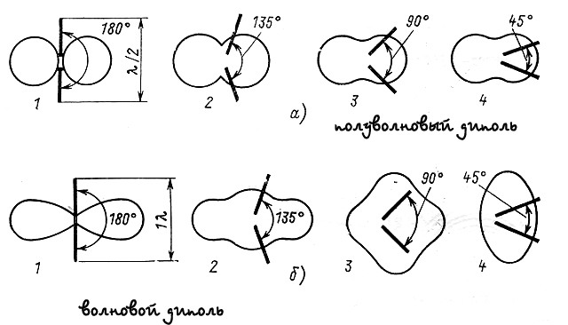
The transmitting antenna pattern can be constructed by turning it and measuring the field strength at a fixed distance and without changing the transmission frequency. These measurements are transformed into graphical form give a representation in which direction antenna has a maximum gain factor, i.e. The polar diagram shows the direction in which the energy emitted by the antenna in horizontal and vertical planes is concentrated. In amateur practice, this is the most complex type of measurement. Conducting measurements in the near zone it is necessary to consider a number of factors affecting the accuracy of measurements. Any antenna except the main petal has a number of lateral petals, in the range of short waves we cannot raise an antenna for a large height. When measuring the radiation diagram in the range of the side petal, reflected from the Earth or from the near building, it can get to the measuring probe, both in the phase and in antiphase, which will result in error in measurements.
The orientation diagram is also a simple wire antennas. For example, the dipole - eight with deep dips in the chart that is not good. The most popular antenna Inverted V.
If all the textbooks on radio engineering or Rothhamel are well remembered, then the inverted (dipole) has an o-dimensional diagram. Those. There are deep failures. And if you change the position of the canvas, change one pair places (moving the canvas of one antenna, for example, at an angle of 90 degrees), the diagram begins to approach conventionally in thick sausage. But the most important thing is to disappear the failures, and the diagram "is rounded". Diple has enough to change the angle between halves. And if you do this angle from a wave dipole to 90 °, then with some stretch the radiation diagram can be called circular.
Bandwidth
As a rule, two classes of antennas distinguish: narrowband and broadband. It is very important that in the operating frequency interval supported good matching and a given strengthening. The bandwidth of the antenna should not change when the transmitter or receiver frequency is restructuring. Narrowband antennas include all simple resonance antennas, as well as directed such as the "wave canal" and "square". Me, like an avid telegraphist, quite suit antennas with a strip of 100 kHz, but there are universals, SSB lovers, so the manufacturers of the antennas are trying to provide a bandwidth equal to the width of the radio amateurs. For example, an antenna of the wave canal "on the radio amateur range of 14 MHz should have a bandwidth of at least 300 kHz (14000 - 14300 kHz) and, moreover, good matching in this frequency band. Broadband antennas are characterized by a large frequency change range, in which the operating properties of the antenna are preserved, many times superior in this respect resonant systems. These include speakeriodic and spiral antennas.

Efficiency ratio (efficiency)
A portion of the power supply to the antenna is emitted to the space, and the other part in the antenna conductors turns into heat. Therefore, the antenna can be represented as an equivalent load resistance consisting of two parallel components: radiation resistance and resistance of loss. The effectiveness of the antenna is characterized by its efficiency or the ratio of the beneficial (emitted) power to the total power supplied to the antenna. The greater the resistance of radiation in relation to the resistance of the loss, the greater the KGID antenna. It is obvious that good electrical contacts And small ohmic resistance (the thickness of the elements) is good.
As you can see, this parameter is interested in us in the all-day queue and is not the main thing. (God forbid you think that his bad meaning can not be upset. If the KSV is more than two - it is bad). If the antenna is configured to the resonance and during the setting, we compensated for its reactivity, and agreed with feeder feeder by resistance, then the KSV will be equal to one. Just do not use the device built into the transceiver as an ARV meter. He is more indicator. Plus, a vehicle is not always discouraged. And we want to know the truth. 🙂 And do not forget about symmetrization (see above). It is known that you can power the antennas with a coaxial cable any length, then it is an asymmetrical coaxial cable, but in the case when two antennas are powered by one cable, it is better to make sure that for both calculated frequencies, the length of the cable is a multiple half-wave.
For example, for a frequency of 14,100, the cable length should be:
100 / 14.1 x 1; 2; 3; 4, etc. \u003d 7.09m; 14,18m; 21,27m; 28.36m, etc.
For 21,100 MHz, respectively:
100 / 21.1 x 1; 2; 3; 4, etc. \u003d 4.74m; 9,48m; 14,22m; 18.96m; 23.70; 28.44, etc.
Usually, the people consider the minimum length of the feeder to be a priority, and if you calculate some large lengths, we will see that for ranges 15 and 20 meters the first "multiplicity" will come with a cable length of 14.18 and 14.22 meters, the second, respectively, 28.44 meter and 28.36 meters. Those. The difference in the 4-re centimeter, the PL259 connector is long. 🙂 This magnitude is neglecting and have one feeder for two antennas. Calculate the "multiple length" of the feeder for bands 80 and 40 meters for you is now not difficult. If we have not forgotten about symmetrization, now we can customize the antenna with confidence that the feeder does not make any interference to the purity of the experiment. Very good option Two double inverters on two masts: 40 and 80 + 20 and 15 meters. With this option (well, another GP is 28 MHz in case there is a passage) EN5R leaves almost all expeditions.
Well, now we are armed with theoretical knowledge of the properties of the antennas and adequately can perceive tips on their execution and configuration. Of course, all theoretically, because you are visible in place. The most popular among the antennas for radio amateurs - dipole. So, the original conditions: we can lift-omit the dipole for half an hour and many times a day. Then, most likely, it makes no sense to spend time on pre-tuning Its on Earth: It will not be easy to perform for its work at the height of the suspension. From preliminary theoretical knowledge, you will only need information that the dipole's working frequency near the ground with the rise "will leave" up 5-7 percent. For example, for a 20 meter range is 200-300 kHz.
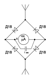
To configure in a resonance with a working frequency of a conventional dipole, you can use (except the system to lower-cut-raise) or the SVIP-GENARATOR (many know this device under the name of the GCC), or a gir or, at worst, exercise and oscilloscope. It is clear that if there are no such devices, you will have to adjust the dipole web into the resonance using an ordinary field indicator, or as it is also called the probe. This is an ordinary dipole with long cloths at least ten times less than the calculated length of the antenna itself, connected to the rectifier bridge (better on Germany diodes - will respond to less voltage) loaded to the usual emergency device - Micro ammeter S. maximum size Scale (to be better visible). It will be better if the probe is with a circuit (filter) to the operating frequency, so as not to tune in to the neighbor's mobile phone, and with an amplifier. For example, such. It is clear that you caught the length of the dipole to the maximum of its radiation at the operating frequency. The minimum of the CWW in this case should form a machine gun. If not, remember the symmetrization. If it does not help and the value of the KSV is still high - you have to recall the methods of coordination. Although it happens very rarely.

The following composition is a few dipoles on one cable. Well, read about the cable above, and about the web should be aware of the following: for their minimal effect of one on another, they should be stretched at an angle of 90 degrees. If there is no such possibility, then after the correction is the length of one, most likely it is necessary to adjust the other. Several Inv V. one cable - the option described above and is distinguished only to the fact that it is possible to "push" the CWS to the minimum value by adjusting the angle of inclination to the vertical (to the mast), which, of course, is easier than manufacturer matching device And even easier for the next fit of the Dinna of the canvas.
So, it turns out that the sequence of actions should be performed - first the antenna is set to resonance, and then achieve a minimum CWW in the required frequency band. All this is true for simple dipole antennas. And it is very complicated, in case the antenna is multi-element. In this embodiment, without special devices, it is not necessary to do without only a system with several unknown, but also achieve quite certain directed properties.
The setting includes the measurement of the basic parameters of the antenna and the correction of them by fitting the linear dimensions of the antenna elements, distances between the elements, the settings of the matching and symmetrical devices. Tip: Trust Specialists. As the famous Belarusian shortwave spoke Vladimir Prikhodko EW8AU, "setting up an antenna only on the CWS, it is possible to make a good agreed load from the antenna for the output cascade of the transmitter. It will work well in normal mode, only an antenna can have a bad radiation pattern, low efficiency, part of the power will be spent on heating the antenna elements and the antenna feeder path and the most unpleasant thing, which may be for the radio amateur - this is interference with television " .
 Causes of why Flash Player does not work, and troubleshooting
 The laptop itself turns off, what to do?
 HP Pavilion DV6: Characteristics and Reviews
 Format representation of a floating point numbers How negative numbers are stored in the computer's memory
 Computer fries and does not turn on what to do?
 Why does not work mouse on a laptop or mouse?
 How to increase or decrease the scale of the page (font) in classmates?