How to check the BS antenna parameters 2. I.M. Sparrow. Equipment and operation of radio stations. Basic stations antennas. Ploy inside
And again a little comprehensive material. This time it will be discussed about base stations. Consider various technical points on their placement, design and range of action, as well as to look inside the same antenna block.
Basic stations. General
So the cellular antennas, mounted on the roofs of buildings look. These antennas are an element of a base station (BS), and specifically - a device for receiving and transmitting a radio signal from one subscriber to another, and then through the amplifier to the base station controller and other devices. Being the most noticeable part of the BS, they are installed on the antenna masts, roofs of residential and industrial buildings and even flue pipes. Today, you can meet more exotic options for their installation, in Russia they are already installed on the lighting columns, and in Egypt they will even "mask" under the palm trees.

Connecting the base station to the network operator network can be carried out on a radio relay communication, so near the "rectangular" antennas BS blocks can be seen a radio relay plate:

With the transition to more modern standards of the fourth and fifth generations, to meet their requirements, it will be necessary to connect the stations exclusively by fiber optics. In modern BS structures, fiber becomes an integral medium of information transmission, even between nodes and BS units. For example, in Figure below shows the device of a modern base station, where the fiber optic cable is used to transmit data from RRU (remote controlled modules) antennas to the base station (shown by the orange line).

The basic station equipment is located in non-residential buildings of the building, or installed in specialized containers (fixed on walls or pillars), because modern equipment is performed quite compactly and can easily fit into the system block of the server computer. Often, the radio module is installed next to the antenna block, it allows you to reduce the loss and dispersion transmitted to the power antenna. Thus, three installed radio modulus of equipment of the Flexi Multiradio base station, fixed directly on the mast look like:

Base Station Service Zone
To begin, it should be noted that there are various types of base stations: macro, micro, pico and femotosotes. Let's start with the small one. And, if briefly, the femtosote is not a base station. This is Rather, Access Point (Access Point). This equipment is initially focused on a home or office user and the owner of such equipment is private or JUR. The person who is not believed to the operator. The main difference of such equipment is that it has a fully automatic configuration, ranging from the rating of radio parameters and ending with the operator's network connected to the network. Femtosota has dimensions of a home router:

Picosote is a low power BS, which belongs to the operator and using IP / Ethernet as a transport network. Usually installed in the locations of the possible local concentration of users. The device in size is comparable to a small laptop:

The microstision is an approximate version of the implementation of the base station in a compact form, is very common in the networks of operators. From the "large" base station, it is distinguished by the trimmed capacity of the subscriber supported by the subscriber and smaller radiating power. Mass, as a rule, up to 50 kg and radius of radio flow - up to 5 km. This solution is used where the high capacity and network power is not needed, or there is no possibility to install a large station:

Finally, macros is a standard base station, on the basis of which mobile networks are built. It is characterized by the power of about 50 W and the coating radius of up to 100 km (in the limit). The rack mass can reach 300 kg.
The coverage zone of each BS depends on the height of the antenna section, from the terrain and the number of obstacles to the subscriber. When installing the base station, it is far from always to the fore the coating radius. As the subscriber base increases, it may not have enough maximum BS bandwidth, in which case the message "Network is busy" appears on the phone screen. Then the operator over time on this territory can consciously reduce the radius of the base station and establish several additional stations in the places of the greatest load.
When you need to increase the tank of the network and reduce the load on separate base stations, then come to the help of microsts. In a metropolis, a single microstatic radioculation zone can be only 500 meters.
In the conditions of the city, oddly enough, there are places where the operator needs to locally connect a plot with a large number of traffic (metro stations areas, large central streets, etc.). In this case, low-power microsts and picosotes are used, the antenna blocks of which can be placed on low buildings and on pillars of street lighting. When there is a question of organizing a quality radiocrying inside closed buildings (trade and business centers, hypermarkets, etc.) then pico-bottle base stations come to the rescue.
Outside the cities, the range of works of individual base stations is coming out, so the installation of each base station in removal from the city is becoming an ever more expensive enterprise due to the need to build power lines, roads and tags in complex climatic and technological conditions. To increase the coating zone, it is desirable to install the BS at higher masts, use the directed sector emitters, and lower frequencies less affected by attenuation.

For example, in the 1800 MHz range, the BS distance does not exceed 6-7 kilometers, and in the case of using a 900-mega-megaczo range, the coating zone can reach 32 kilometers, with other things being equal.
Basic stations antennas. Ploy inside
In cellular communication, sector panel antennas are most often used, which have an orphanage diagram of 120, 90, 60 and 30 degrees. Accordingly, the organization of communication in all directions (from 0 to 360) may require 3 (width of 120 degrees) or 6 (width of 60 degrees) of the antenna blocks. An example of an uniform coating organization in all directions is shown in the figure below:

And below the type of type patterns in the logarithmic scale.

Most antennas of basic broadband base stations that allow working in one, two or three frequency bands. Starting with UMTS networks, unlike GSM, the basic stations antennas are able to change the radiocrying area depending on the load on the network. One of the most effective methods for controlling the radiated power is to control an antenna tilt angle, in such a way the area of \u200b\u200birradiation area of \u200b\u200bthe orientation chart changes.
Antennas may have a fixed inclination angle, or have the ability to remotely adjust using a special software located in the BS control unit, and built-in phase pane. There are also solutions that allow you to change the service area, from the general data network management system. Thus, you can adjust the service area of \u200b\u200bthe entire base station sector.
The antennas of base stations use both mechanical control of the diagram and electric. Mechanical management is easier to be implemented, but often leads to distortion of the form of a focus chart due to the influence of the structural parts. Most BS antennas has an electrical adjustment system of inclination.
The modern antenna block is a group of radiating elements of an antenna array. The distance between the elements of the lattice is chosen in such a way as to obtain the smallest level of lateral petals of the radiation pattern. Most often there are lengths of panel antennas from 0.7 to 2.6 meters (for multidia-band antenna panels). The gain varies from 12 to 20 DBI.
Figure below (left) presents the design of one of the most common (but already outdated) antenna panels.

Here, the emitters of the antenna panel are half-wave symmetric electrical vibrators over the conductive screen, located at an angle of 45 degrees. This design allows you to form a diagram with the width of the main petal 65 or 90 degrees. In such a design, two- and even three-sample antenna blocks (truth, rather large) are produced. For example, a three-frame antenna panel of such a design (900, 1800, 2100 MHz) differs from one-band, approximately two times the large size and mass, which, of course, makes it difficult to maintain it.
An alternative technology for the manufacture of such antennas involves the performance of striped antenna emitters (metal plates of the square shape), in the figure above the right.
But another option when half-wave slot magnetic vibrators are used as the emitter. The power line, slots and the screen are performed on the same printed circuit board with a double-sided foil glassstolic:

Taking into account the modern realities of the development of wireless technologies, the base stations must support the operation of 2G, 3G and LTE networks. And if blocks of control of base stations of networks of different generations can be accommodated in one switching cabinet without increasing the overall size, then significant difficulties arise with an antenna part.
For example, in multidia-band antenna panels, the number of coaxial connecting lines reaches 100 meters! Such a significant cable length and the number of soldered joints inevitably leads to losses in lines and a decrease in gain coefficient:

In order to reduce electrical losses and reducing soldering points, microstrip lines are often made, it allows you to perform dipoles and the system of nutrition of the entire antenna by unified printing technology. This technologies are simple in production and ensures high repeatability of the characteristics of the antenna during its serial release.
Multi-band antennas
The development of third and fourth-generation communication networks requires the upgrades of the antenna part of both base stations and cell phones. Antennas should work in new additional ranges exceeding 2.2 GHz. Moreover, work in two and even three bands should be made simultaneously. As a result, the antenna part includes rather complex electromechanical schemes that should ensure proper functioning in difficult climatic conditions.
As an example, consider the design of the emitters of the dual-band antenna of the PowerWave cellular base station, operating in the ranges of 824-960, MHz and 1710-2170, MHz. Its appearance is shown in the figure below:

This dual-band irradiator consists of two metal plates. The fact that larger size operates in the lower range of 900 MHz, the plate with a smaller slotted emitter is located above it. Both antennas are excited by slotted emitters and thus have a single setting line.
If dipole antennas are used as emitters, then it is necessary to put a separate dipole for each wave range. Separate dipoles must have their own washing line, which, of course, reduces the overall reliability of the system and increases energy consumption. An example of such a design is the Kathrein antenna for the same frequency range as the above:

Thus, dipoles for the lower range of frequencies are as if within the dipoles of the upper range.
For the implementation of three- (or more) range modes of operation, printed multilayer antennas possess the highest technologicality. In such antennas, each new layer works in a rather narrow frequency range. Such a "multi-storey" design is made of printed antennas with individual emitters, each antenna is configured to separate frequencies of the operating range. The design is illustrated in the picture below:
As in any other multi-element antennas in such a design, the elements operating in different frequency ranges occurs. Of course, this interaction affects the direction and harmonization of the antennas, but this interaction can be eliminated by methods used in the headlights (phased antenna arrays). For example, one of the most effective methods is the change in the structural parameters of the elements by offsetting the excitation device, as well as the change in the size of the emulsion itself and the thickness of the separation dielectric layer.
An important point is that all modern wireless technology broadband and the frequency bandwidth is at least 0.2 GHz. Antennas based on complementary structures have a wide working strip of frequencies, a typical example of which are "Bow-Tie" antennas (butterfly). Coordination of such an antenna with a transfer line is carried out by selecting an excitation point and optimizing its configuration. To expand the working frequency band in the coordination of the "Butterfly" complement the input resistance of a capacitive nature.
Simulation and calculation of similar antennas are produced in SAD specialized software packages. Modern programs allow you to simulate an antenna in a translucent case in the presence of the effect of various structural elements of the antenna system and thereby allow you to produce a fairly accurate engineering analysis.
The design of multi-band antenna is produced in stages. First, they calculate and design a microstrip printing antenna with a wide bandwidth for each operating frequency range separately. Next, printed antennas of different ranges are combined (overlaying each other) and consider their joint work, eliminating the cause of mutual influence.

Broadband Antenna of the "Butterfly" type can be successfully used as a base for a three-frame printed antenna. Figure below shows four different options for its configuration.

The presented constructions of the antennas are distinguished by the form of the reactive element, which is used to expand the working band of the frequency in the coordination. Each layer of such a three-frame antenna is a microforn emitter of the specified geometric sizes. The lower frequency - the greater the relative size of such a emitter. Each layer of the printed circuit board is separated from the other with a dielectric. The presented design can operate in the GSM 1900 range (1850-1990 MHz) - takes the lower layer; WiMAX (2.5 - 2.69 GHz) - takes the middle layer; WiMAX (3.3 - 3.5 GHz) - takes the top layer. A similar design of the antenna system will allow and transmit a radio signal without using additional active equipment without increasing the overall dimensions of the antenna block.
And in conclusion a little about the dangers of BS
Sometimes, the basic stations of cellular operators are installed directly on the roofs of residential buildings than specifically demoralize some of their inhabitants. The owners of the apartments cease to "give birth to cats", and at the head of the grandmother, gray hair begin to appear faster. In the meantime, the residents of this house of the electromagnetic field are almost not obtained from the installed base station, for the "down" base station does not radiate. Yes, and, by the way, the norms of Sanpin for electromagnetic radiation in the Russian Federation are an order of magnitude lower than in the "developed" countries of the West, and therefore, in the city, the base stations never work at full capacity. Thus, harm from the BS is not, unless you make a roof on the roof in a pair of meters from them. Often, with a dozen points of access installed in the apartments of residents, as well as microwave furnaces and cell phones (pressed to the head) have a much greater impact on you, rather than a base station installed 100 meters outside the building.
Reception of decameral waves is accompanied by deeplarming and requires the change of working frequencies in time depending on the state of the ionosphere. To increase the reliability of radio communications, a dual (less common) reception is used for two (three) receiver working with dismissed antennas spaced in space. As a result, the number of antennas at the receiving station turns out to be quite large. To reduce the number of antennas, feeders and simplifying their switching, receiving antennas must be wideband. In these antennas, you can allow slightly reduced efficiency, since the signal levels and external interference decrease the same and the signal-to-noise ratio will not change. As the receptions are used symmetric and unsimarious antennas of the running wave.
The symmetric antennas of the running wave are a system of horizontal symmetric vibrators (Fig. 17, a), uniformly located in space and connected through resistance to the disposal line.
The collective line is performed by a multi-wire with a reduced wave resistance W \u003d 160-200 Ohm. From one end, the collective line by means of a feeder is connected to the receiver, and from the other - it closes to the resistance R \u003d WO. The number and length of the vibrators is desirable to take large, and the power received by the antenna increases. However, an increase in the length of the shoulder more than 0.64λ is undesirable because it leads to an increase in the levels of lateral petals. To work in the wave range of 12.5 ... 70 m, the length of the vibrator shoulder is chosen equal to L \u003d 0.64λCOR \u003d 8 m. The length of the antenna L (collective line) is determined by the value of the KND. Of
Constructive considerations The length of the antenna limit the value of 90 ... 100 m. With an increase in the number of vibrators, the active antenna length increases and the distance between the vibrators is reduced. At distances between vibrators less than 0.5λ. A further decrease in this distance is poorly affected by the levels of lateral petals, but the shunt action of vibrators on the collecting line increases. The distance between the vibrators is chosen within D \u003d (0.3 ... 0.4) λkor, and the number of vibrators n \u003d 20-30.

In the general case, the input impedance of the vibrator is complex. The direct connection of the vibrators to the collecting line changes its power parameters, the phase speed in it will change. Any connection to the line of concentrated resistance violates the homogeneity of the line and causes some reflection of the energy from the connection points. To reduce the shunt action and reflection, the vibrators to the collector line are connected through the connection resistance. Active resistance can be used as a resistance of communication (Fig. 17, a), the condenser (Fig. 17, 7.6) or inductance (Fig. 17, B). In accordance with this, the antennas of the running wave are designated BS, BE or BI.
From economic consideration, the height of the antennas is reduced to 17 ... 25 m.
Figure 19 shows the bottom of the antenna of the running wave. In comparison with the syphase and rhombic BS antennas have smaller levels of lateral petals. Active communication resistance exclude resonant phenomena, allow you to increase the lengths of the vibrators and get a much larger overlap of the range. One BS antenna practically overlaps the entire range of decamen waves. With increasing communication resistance, the effect of vibrators on a collecting line is reduced, coordination improves, but due to the increase of losses deteriorates to the efficiency. Low efficiency allows the use of a running wave antennas only as receiving.
For the narrowing of the day and increasing the DND, the two canvases of the antennas are located near and are connected in parallel with the help of exponential feeder transformers.
In the practice of radio communications, BS-2 (21/8) (200 / 4.5) 25 (21/8) (200 / 4.5) 25 was widely distributed. This designation has the following decoding: an antenna of a traveling wave (b) with active coupling resistances (C) consists of two parallel connected canvas (2). Each web has a 21 symmetric vibrator with a shoulder length L \u003d 8 m and the distance between them d \u003d 4.5m. Resistance to communication in each shoulder of the vibrator for 200 ohms. The canvas have the height of the suspension above the ground 25m.
Under conditions of the dimensions of the antenna field, the dual reception can be carried out using antennas with mutually perpendicular vibrators (polarization-separated reception). If one of the antennas has horizontal vibrators, such as BS, the second must have vertical vibrators. Such an antenna may be a BSVN - a vertical asymmetric antenna of a running wave, whose vibrators are associated with a collective line through active resistance (resistors) of communication (Fig. 19, a). The number of vibrators, their length and distances between them are chosen from the same considerations as for the BS antenna, the collective line (Fig. 19,6) is performed as a notymmetric, multi-wire with a wave resistance of 140 ohms. External collecting line wires under each vibrator are grounded. Vibrators through the resistance of the 350 ... 800 ohms are connected to two internal wires. BSVN antennas compared to the BS have a smaller value.
The BSVN2 antenna compared to the BS2 in the horizontal plane has several large levels of lateral petals, since the vertical vibrator in the horizontal plane does not have directional properties. The radiation diagram of the BSVN antenna in the vertical plane essentially depends on the soil parameters. With perfectly conducting soil, the maximum of the main petal of the DN coincides with the direction along the Earth. Under the actual conductivity of the soil, the wave propagating along the earth's surface is tested and the direction of the main petal is with the land plane of the angle of 10 ... 200.

In the range of decamer waves as a receiving antenna, a wire with a diameter of 3 ... 4 mm long with a length of 100 ... 300 m, located at an altitude of 2.5 ... 3.5 m above the ground, elongated in the direction on the correspondent . To one end, a receiving feeder is connected through the coordinating transformer, and to the other - through the load resistance equal to the wave resistance of the wire - grounding or counterweight.
Vertical wires at the beginning and end of the antenna can significantly worsen its directional properties. To reduce the lengths of these wires, the load resistance at the end and the outer conductor of the feeder at the beginning of the antenna is connected not to grounding, but to the highlights raised above the ground. When operating at a single frequency, the counterweights can be made of three rays located in a horizontal plane diverging at angles of 120 ° and having a length of 0.25 λ, each. When operating in the range, the counterweights are performed by multipath, the length of the rays of which is chosen according to the logo-periodic law. The counterweight represents a system of 15 rays located in a horizontal plane, divergent in the angle of 360/15 \u003d 24 ° to each other.
To reduce the wave resistance, the antenna wire is performed from several wires separated in space. When working on the tracks of a small length of the angle of arrival of the wave Δ≥40 ° and the antenna length is small. For example, at δ \u003d 40 ° LOPT \u003d 2K, and at δ \u003d 60 ° LOP \u003d λ. Such antennas have weak directed properties. To improve the directional properties, the antenna is performed as a syphan lattice of two or more wires.
When working with long-range correspondents, when the angles of the arrival of the wave in the vertical plane Δ≤18 °, the optimal length of the antenna LOPT≥10λ. The directed properties of such an antenna are better.
Antenna, which is a syphase grid, consisting of two wires, separated by 20 ... 60 m, with the length of each wire 100 ... 300 m, can be used on high long-length communication lines as temporary or backup.
On the length of the length of over 2000 km use a dual receipt for the antenna separated in the space. If the spatial separation of the antennas is difficult to apply the polarization-separated reception using the BS2 antennas and BSVN2, having vertical BSVN2 vibrators directly under the collective lines of the BS2 antenna.
1) Where is the basic station better?
The base station should be placed at a high point in such a way that the maximum number of clients can see its antennas. It can be a roof of a high building, tower, factory pipe, etc.
2) What equipment is necessary to create a base station (BS)?
Simplest base station (BS) consists of:
but. wireless Router RES "Rapira"
b. RF Cable with N. Connectors To connect to the router, the N-MALE connector is used. Depending on the type of antenna on the other end of the cable, N-Male, N-Female or other connector can be used.
in. Antenna - sector or omnidirectional
Cable Cable Lower Stp Cat.5
D. Power Injector (included in the distribution of RPP "Rapira")
High performance BS may consist of 3 or 6 such sets that provide a coating of 360 degrees in azimuth. When using a version of a radio collar with two wireless interfaces, one router can be installed on 2 sectoral antennas, provided that the transmission frequency is removed from each other by at least 100 MHz.
3) How many clients can be connected to one base station?
One base station Can serve up to 128 customers on the sector. It should be remembered that the bandwidth of the base station is divided between all clients. Thus, the speed available to each of the customers depends on the total number of clients, the load, which each of them creates, the number and activity of computers in local networks hiding behind client routers. You can influence the distribution of base station resources using the means QoS., shapeing and prioritization to highlight each client the bandwidth you need.
4) What do I need to connect the local client network to the BS?
You will need:
but. RPP Router "Rapira" configured in mode wirelessclient
b. RF Cable with connectors. A N-MALE connector is used to connect to the router. Depending on the type of antenna on the other end of the cable, N-Male, N-Female or other connector can be used.
in. Antenna Directional - Parabolic or Planar (Panel)
G. Cable reduction type STP Cat.5 (up to 100m)
D. Power Injector (included in the package of RES "Rapira")
Depending on the results of the energy calculation, the antenna is selected with the required gain. Antenna is mounted so that direct visibility is ensured before the base station antenna.
The router is a gateway for the client LAN computers. The LAN client can be protected by Firewall tools built into a wireless router. You can also use the DHCP server function to automatically distribute IP addresses and the NAT function to hide the entire LAN client over one IP.
5) How many local client networks can be connected to a wireless network by means of a single RPP wireless router?
RES "Rapira" It has one interface in the "street" version and 2 interfaces in "room". Accordingly, the number of interfaces you can connect 1 or 2 networks. RES "Rapira" Also supports VLAN. By connecting the VLAN 802.11q support to the radio asterorate, you can create up to 255 virtual interfaces and connect the appropriate number of local networks from each other, providing routing between them and distinguishing access sheets of Firewall access sheets.
6) Can there be a limited bandwidth for each of the clients?
Yes, the speed in the direction "to the client" can be centrally limited to the BS using the Shaping function. In the direction of "from the client", the speed can be set on client radiocructures.
7) What is the maximum radius of servicing the base station?
Maximum service radius, i.e. The distance from the BS to the very remote client depends in particular from the following factors:
but. The transmitter power (depends on the modulation) and the sensitivity of the receiver, which in turn also depends on the selected speed (modulation).
b. Strengthening BS antenna and client antenna
in. Losses in microwave cables and connectors (depends on their type and cable length)
D. The presence of obstacles for the distribution of the wave in the 1st zone of Fresnel
e. noise from systems operating on the same or close frequency
Usually, the BS cell radius does not exceed 10-15km. It allows you to pre-evaluate the maximum service radius when using various antennas and amplifiers.
8) Can I use amplifiers to increase the service radius or channel length point - point?
Yes, you can use an external amplifier amplifier. Modifications RES "Rapira" PA400 Contain a built-in bidirectional amplifier. Using the version PA400. Allows up to 10db to raise the signal to the transmission, the sensitivity to 2-3db and helps to increase the service radius of 2-4 times. Using the version PA400. The built-in amplifier provides significant savings and additional operational benefits.
9) How to choose an antenna for a client station or channel point - point?
Remember the old and wise rule "Antenna is the best amplifier." Unlike the amplifier, the antenna does not contribute additional noise and does not enhance the interference with the useful signal at the reception. A good directional antenna allows you to "distort" from interference towards the use of a narrow beam. For example, a parabolic antenna with a diameter of 0.9m provides an increase in 30DB and provides a width of the beam of about 3 degrees. At a distance of 5 kilometers, such an antenna gives a "stain" of radiation with a radius of only about 130 meters. In the range of 5-6 GHz, the antenna dimensions required to achieve the appropriate gain is less than for 2.3 - 2.5 GHz. Remember that parabolic antennas have the best characteristics by the level of rear and side petals compared with planar antennas.
10) How to choose antennas for a base station?
Antennas forbase station It is better to use sector. The smaller the angle (sector) of the service, the less interference will "collect" such an antenna, but the greater the routers and frequency channels will require such a BS to cover the desired sector. Most common antennaswith the width of the main petal 60, 90 and 120 degrees with gain from 15 to 13db. Usually in the vertical plane, the width of the petal is 6-8 degrees, that is, the radiation "pressed" to the ground and extends along the horizon. The smaller the width of the main petal antennasMoreover, its reinforcement due to the concentration of emitted energy. For selectand adjustment antennasyou should use the appropriate calculation to calculate the necessary tilt antenna At the corner of the place. Too small radiation angle in the vertical plane can limit customer connection near the base station, especially if the latter is too high.
The use of an antennas with a circular orientation diagram of 360 degrees is not recommended when creating a BS with a large planned radius of maintenance and customer number, especially in interference conditions. In addition, the plane of the radiation of the omnidirectional antennasdirected strictly horizontally and close subscribers located below the BS will experience difficulties with communication.
12) Does "direct visibility" need?
Yes, direct visibility It is necessary in most cases. This means that on an imaginary straight line between the antennas of devices should not be physical obstacles (trees, buildings, etc.). It should also be taken into account the nature of the wave propagation and make a reserve for diffraction ().
13) What is Fresnel zones?
Fresnel zones are the space around the imaginary line "Direct Visibility", in which the radio wave applies. At least 80% of this zone, in which the main power of radiation, should also be free from obstacles, otherwise the signal will be weakened. If you want to "shoot" in the slot between the two houses, first the diameter of the 1st Fresnel zone. For example, for the 5.8 GHz channel, the 16km length of the Fresnel zone in the middle of the link is a circle with a radius of 14m. The gap between the houses should be at least 28m. For 2.4 GHz, the radius of the Fresnel zone will already be 34m.
14) Can I "transparent" to combine 2 LAN?
Yes, you can provide transparent traffic through wireless Rooter RoutersBy configuring them to work in Bridge mode. At the same time, Ethernet frames are filtered by dynamic table MAC addresses before sending to ether. Read more at the construction siteequipment for work in this mode, read in the instruction manual.
15) How much time is required for mounting the simplest wireless network?
Very little! A qualified brigade of 2 people is usually required no more than one day to mount the channel point - point. Installation of the base station Of the 3 sectors and connecting 5 customers will require 2-3 days.
16) What length and varieties of HF cable use?
Shortest length. Remember that at frequencies 2.3 - 2.5GHz, and even more than 5-6 GHz cable introduces very significant attenuation. RES "Rapira" Specially has all-weather execution to ensure the possibility of mounting directly next to the antenna. At the same time, you can use a flexible and convenient in handling a 8D-FB cable (blue or green) or a similar one. If you want to place an antenna on removing 10 - 20m from the router, you should use either a thick flexible cable with low attenuation, such as 10D-FB, or a hard cable with the corresponding connectors. We recommend using cables with a solid foamed dielectric. These cables have more stable characteristics and easier in circulation. Cables with a dielectric in the form of a airbap, for example, the distributed DX-10 brand (yellow cable) have a number of unpleasant flaws:
a. When installing the plugs of the soldering, as well as from heating when heat-insulating waterproofing, a thin inner dielectric melts and the cable loses the properties, it begins to make a huge attenuation
b. In the process of operation due to the drops of outdoor temperature and the associated periodic airproof occurrence, the moisture is accumulated in the dielectric cavity from time to which the cable loses performance
C.. Cables change properties when bending, because the central lived is poorly fixed
Cellular communication has recently entered our daily life so firmly, it is difficult to submit modern society without it. Like many other great inventions, the mobile phone has greatly influenced our life, and for many of its spheres. It is difficult to tell what the future would be if it were not for this convenient type of communication. Surely the same as in the film "Back to the Future-2", where there are flying cars, hover boards, and much more, but there is no cellular!
But today in a special report for will not be a story about the future, but about how modern cellular communication works and works.
In order to learn about the work of modern cellular communication in 3G / 4G format, I asked for a visit to the new federal operator Tele2 and spent a whole day with their engineers who explained to me all the subtleties of data transmissions through our mobile phones.
But I will first tell a little about the history of cellular communication.
The principles of the work of the unproductive communication were tested almost 70 years ago - the first public moving radiotelephone appeared in 1946 in St. Louis, the United States. In the Soviet Union, an experienced sample of a mobile radio telephone was created in 1957, then scientists of other countries created such devices with various characteristics, and only in the 70s of the last century in America, modern principles of cellular communication were identified, after which its development began.

Martin Cooper - the inventor of the prototype of a portable cell phone Motorola Dynatac weighing 1.15 kg and dimensions of 22,5x12,5x3.75 cm

If in Western countries by the mid-90s of the last century, the cellular communication was common everywhere and most of the population used it, then in Russia she just began to appear, and became accessible to everyone just over 10 years ago.

Bulky brick-like mobile phones who worked in the formats of the first and second generations went down to history, giving way to smartphones with 3G and 4G, the best voice communication and high speed of the Internet.
Why is the connection called cellular? Because the territory on which communication is associated is divided into separate cells or cells, in the center of which base stations (BS) are located. In each "honeycom", the subscriber receives the same set of services in certain territorial boundaries. This means that moving from one "honeycomb" to another, the subscriber does not feel the territorial attachment and can freely use the services of communication.
It is very important that there is a connection continuity when moving. This is ensured by the so-called Handover (handover), in which the connection established by the subscriber as it would be picked up by adjacent cells along the relay, and the subscriber continues to talk or dig in social networks.
The entire network is divided into two subsystems: the subsystem of base stations and the switching subsystem. Schematically, it looks like this:

In the middle of the "honeycomb", as mentioned above is the base station, which usually serves three "honeycombs". Radio signal from the base station is emitted through 3 sector antennas, each of which is directed to its "honeycomb". It happens that on one "honeycom" several antennas of one base station are directed at once. This is due to the fact that the cellular network operates in several ranges (900 and 1800 MHz). In addition, this base station may present equipment of several generations of communication (2G and 3G).
But on the BS TELE2, there is only the third and fourth generation equipment - 3G / 4G, since the company decided to abandon old formats in favor of new, which help avoid voice breaks and provide more stable Internet. Priséouts of social networks will support me that in our time the speed of the Internet is very important, 100-200 Kb / s no longer enough, as it was a couple of years ago.
The most familiar placement of the BS is a tower or mast, built specifically for it. Surely you could see the Red-White Ties BS somewhere in remoteness from residential buildings (in the field, on the hill), or where there are no high buildings nearby. As this, which is visible from my window.

However, in the conditions of urban areas it is difficult to find a place to place a massive structure. Therefore, in large cities, base stations are placed on buildings. Each station catches a signal from mobile phones at a distance of up to 35 km.

These are antennas, the BS equipment itself is in the attic, or in the roof container, which is a pair of iron cabinets.

Some basic stations are located where you can not even guess. How, for example, on the roof of this parking lot.


The BS antenna consists of several sectors, each of which takes / sends a signal to its side. If the vertical antenna communicates with telephones, the round connects the BS with the controller.

Depending on the characteristics, each sector can serve up to 72 calls at the same time. The BS may consist of 6 sectors, and to serve up to 432 calls, but usually sets fewer transmitters and sectors at stations. Cellular operators, such as Tele2, prefer to put more BS to improve the quality of communication. As I was told, here the most modern equipment is used: Ericsson base stations, a transport network - Alcatel Lucent.

From the base stations subsystem, the signal is transmitted towards the switching subsystem, where the connection with the desired subscriber is established. In the switching subsystem, there are a number of databases in which information about subscribers is stored. In addition, this subsystem is responsible for security. If you say easier, then the switch is performed the same functions as the girls operators who previously combined you with the subscriber, only now all this happens automatically.
Equipment for this base station is hidden in this iron cabinet.

In addition to conventional, there are also mobile variants of base stations located on trucks. They are very convenient to use during natural disasters or in places of mass accumulation of people (football stadiums, central squares) for the time of holidays, concerts and various events. But, unfortunately, due to problems in the legislation of widespread use, they have not yet found.

To ensure optimal coating with a radio signal at the ground level, base stations are designed in a special way, because despite the range of 35 km. The signal does not apply to the height of the aircraft flight. However, some airlines have already begun to install small base stations in their sides, providing cellular communication within the aircraft. Such BS is connected to the ground cellular network using the satellite channel. The system is complemented by the control panel, which allows the crew to enable and disable the system, as well as individual types of services, for example, turn off voice over night flights.
I also looked into the Tele2 office to see how experts control the quality of cellular communication. If a few years ago, such a room would be hung to the ceiling by monitors showing network data (loading, network accident, etc.), then over time, the need for such a number of monitors has dropped.

Technology over time has been strongly developed and enough such a small room with several specialists to watch the work of the entire network in Moscow.

A little species from Tele2 office.


At the meeting of the company's employees, plans to seize the capital) Since the beginning of the construction, until today Tele2 managed to cover all Moscow to its network, and gradually conquers the Moscow region, launching more than 100 base stations weekly. Since I live now in the area, it is very important for me. So that this network came as quickly as possible in my town.
The company's plans for 2016. Ensuring high-speed communication in the subway at all stations, at the beginning of 2016, Tele2 is present at 11 stations: Communication 3G / 4G standard on Borisovo metro station, "Business Center", "Kotelniki", "Lermontovsky Prospect" , Troparevo, Shipivskaya, Zyablovko, 3G: "Belorusskaya" (ring), "Spartak", "Pyatnitsky highway", "Zhulebino".

As I said above, Tele2 abandoned GSM format in favor of third and fourth-generation standards - 3G / 4G. This allows you to install 3G / 4G base stations with a larger frequency (for example, within the Moscow Ring Road of the BS, it is about 500 meters from each other) to ensure a more stable connection and high speed of the mobile Internet, which was not in the networks of previous formats.

From the office of the company, I go to one of the points of engineers from Nikifora and Vladimir engineers, where they need to measure the speed of communication. Nikifor stands opposite one of the mast on which equipment is installed to provide communication. If you look closely, notice a little further to the left of another such mast, with the equipment of other cellular operators.

Something strange, but cellular operators often allow their competitors to use their tower facilities to accommodate antennas (naturally on mutually beneficial terms). This is due to the fact that the construction of the tower or mast - expensive pleasure, and this exchange allows you to save a lot of money!

While we measured the speed of communication, Nikifora several times passersby grandmothers and uncle asked whether he was not a spy)) "Yes, the wast radio" Freedom "!).

The equipment actually looks unusual, in his mind you can assume anything.

Specialists from the company a lot of work, if we consider that in Moscow and the area of \u200b\u200bthe company more than 7 thousand. Basic stations: Of these, about 5 thousand. 3G and about 2 thousand. LTE base stations, and recently the number of BS increased by about a thousand.
In just three months in the suburbs, 55% of the total number of new operator base stations in the region were broadcast. At the moment, the company provides high-quality coverage of the territory in which more than 90% of the population of Moscow and the Moscow region live.
By the way, in December, the 3G Tele2 network was recognized as the best in quality among all metropolitan operators.

But I decided to personally check how good the connection is at Tele2, because I acquired a sim card in the nearest shopping center on M.Vakovskaya, with the easiest tariff "very black" for 299 p (400 sms / minutes and 4 GB). By the way, I had a similar Bilaynovsky tariff, which is 100 rubles more expensive.

Checked the speed without leaving away from the box office. Reception - 6.13 Mbps, Transmission - 2.57 Mbps. Considering that I stand in the center of the shopping center is a good result, Tele2's connection well penetrates through the walls of the large shopping center.

On M. Tretyakovskaya. Receiving a signal - 5.82 Mbps, transmission - 3.22 Mbps.

And on M. Krasnogvardeyskaya. Reception - 6.22 MBPS, Transmission - 3.77 Mbps. Measured at the exit from the subway. If we take into account that this is the outskirts of Moscow, it is very decent. I believe that a completely acceptable connection can confidently say that stable, if you consider that Tele2 appeared in Moscow just a couple of months ago.

In the capital, the TELE2 stable connection is, it is good. I really hope that they will come to the area and I can fully enjoy their connection.
Now and you know how the cellular communication works!
If you have a production or service that you want to tell our readers, write to me - Aslan ( [Email Protected] ) And we will make the best report that will see not only the readers of the community, but also the site http://ikasetosdelano.ru
Subscribe also to our groups in facebook, VKontakte, Odnoklassniki and B. google + Pluswhere the most interesting from the community will be laid out, plus materials that are not here and video about how things are arranged in our world.
Jim on the icon and subscribe!
 How to reflash iPhone with PC and iTunes
 Best Bitcoin Wallets for iOS Download application wallet on iPhone
 Lenovo Vibe X2 Description, Features, User Reviews
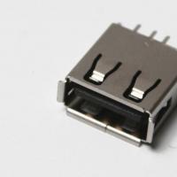 The computer does not see the flash drive: causes and solving the problem
 About Windows Update From Wannacry Encrypter Virus
 Hot browser keys
 New Mac Mini turned out to be five times more powerful than the predecessor