Linear voltage stabilizer LM7805. Homemade power supply based on this module. L7805 L7805CV Stabilizer Connection Scheme Characteristics Connection Scheme
Schematic diagram of a simple and reliable voltage stabilizer from 8 ... 15V to stable 5V. Built based on integral microcircuit L7805. The stabilizer is suitable for powering digital technology, microcontrollers, for charging phones and other devices from stable voltage 5V.
78xx series microcircuits contain several built-in protection:
- Voltage protection and outlet current;
- Thermal protection (from overheating above +125 ° C);
- Built-in powerful diode (protects against reverse current).
Schematic scheme
Figure 1 shows schematic scheme The self-made voltage stabilizer on the L7805 chip. The scheme contains non. a large number of parts that can be further reduced if you do not need to protect against the inlet (D1) stroke and the output voltage indication (R1, LED1).
Fig. 1. The schematic diagram of a simple and reliable voltage stabilizer by 5V (L7805).
Details
As a D1, the Schottky diode can be installed, in the diagram it performs the role of protection against meal chatter or the role of the rectifier if the diagram is connected directly to secondary winding lowering network transformer. Diode D2 protects the output of the chip from the reverse voltage.
Capacitors C2 and C3 - film or ceramic, not polar. The electrolytic capacitor C1 can be installed with a capacity of 50 μF and more, and 10-222μF will be enough for C4. LED1 LED serves to indicate the presence of a voltage of 5V, any LED is suitable here green glow.
This scheme is simple and time-tested. Instead of the L7805 chip, you can install other chips of this series and thus get the voltage stabilizer to other voltages.
Devices that are included in the power supply circuit and maintain a stable output voltage, called voltage stabilizers. These devices are designed for fixed output voltage values: 5, 9 or 12 volts. But there are devices with the presence of adjustment. They can set the desired voltage under certain available limits.
Most stabilizers are designed to a certain greatest current that they are kept. If you exceed this magnitude, the stabilizer fails. Innovative stabilizers are equipped with a current blocking that ensures the shutdown of the device when the highest current is reached in the load and are protected from overheating. Together with stabilizers that support the positive voltage value, there are also devices acting with negative voltage. They are used in two-polar blocks Nutrition.
The 7805 stabilizer is made in the case similar to the transistor. The figure shows three outputs. It is designed to voltage 5 volts and 1 amp current. In the case there is a hole for fixing the stabilizer to the radiator. Model 7805 is a positive voltage device.
The mirror image of this stabilizer is its analog 7905, designed for negative voltage. On the case there will be a positive voltage, a negative value will go to the entrance. From the output is removed -5. To the stabilizers work in normal mode, you need to feed on 10 volts.
Plotovka
The 7805 stabilizer has a pinout, which is shown in the figure. The total conclusion is connected to the case. During the installation of the device, it plays an important role. The last two digits indicate the voltage issued by the chip.
Stabilizers for nutrition chips
Consider the methods of connecting to power digital devicesMade independently on microcontrollers. Any electronic device requires normal operation. proper connection Nutrition. The power supply is calculated on certain power. At its output, a capacitor of a significant amount of capacity for equalizing voltage pulses is established.
Power supplies without stabilization used for routers, cell phones And other equipment, do not combine with the power of microcontrollers directly. The output voltage of these blocks changes, and depends on the connected power. An exception to this rule is charging blocks for smartphones with USB port.where 5 V.
The scheme of the stabilizer, combined with all chips of this type:

If you disassemble the stabilizer and see its insides, the scheme would look like this:

For electronic devices Not sensitive to the accuracy of voltage, such a device will fit. But for accurate equipment you need a high-quality scheme. In our case, the 7805 stabilizer issues the voltage in the range of 4.75-5.25 V, but the current load should not be more than 1 A. Unstable input voltage ranges in the range of 7.5-20 V. The output value will be constantly equal to 5 B. This is the advantage of stabilizers.
As an increase in the load that the chip can give (up to 15 W), the device is better to provide a cooling fan with a radiator installed.
Workable stabilizer scheme:

Technical data:
- The greatest current of 1.5 A.
- Input voltage interval - up to 40 volts.
- Exit - 5 V.
To avoid overheating of the stabilizer, it is necessary to maintain the smallest input voltage of the microcircuit. In our case, the input voltage of 7 volts.
The extra magnitude of the microcircuit power dissipates. The higher the input voltage on the chip, the higher the power consumption, which is converted into the heating of the case. As a result, the microcircuit will overheat and work protection, the device will turn off.
Voltage Stabilizer 5 Volt
Such a device has the difference from similar devices in its simplicity and acceptable stabilization. It uses the K155J1A3 microcircuit. This stabilizer was used for digital devices.

The device consists of working units: launch, source of exemplary voltage, comparison scheme, current amplifier, key on transistors, inductive energy drive with switch on diodes, input and output filters.
After connecting the power, the start-up node, which is made in the form of a voltage stabilizer begins. On the emitter of the transistor, a voltage of 4 V. Diode VD3 is closed. As a result, an exemplary voltage and current amplifier turns on.
The key on the transistors is closed. At the output of the amplifier, a voltage pulse is formed, which opens the key that transmits the current to the energy storage. The stabilizer includes a negative connection scheme, the device goes into operation mode.
All parts applied are thoroughly checked. Before installing the resistor on the board, its value is made equal to 3.3 com. The stabilizer is first connected to 8 volts with a load of 10 ohms, then, if necessary, it is installed on 5 volts.
Fig.1
Recently found in the covers an interesting stabilizer of 7805UC (analog UA7805) in the TO-220 case Fig.1, which was once used in gaming console. I went on the Internet datashitte to this device: the regulator provides a stable output voltage within 4.8 to 5.2V and a current of 1.5a at input voltage from 7 to 25V; operating temperatures from 0 to 125 o C; Output resistance 0.017 ohms. 7805UC can provide peak load on current 2.2a.
The regulator implements the ability to control alternating voltage (positive pulse voltage) In the range from 10Hz to 100kHz with a small noise coefficient - 40 μV.
The stabilizer has an internal current limiter with short closure, as well as protection during thermal overload. I think it will create a good laboratory block Nutrition (BP), or a stabilized block to 5V voltage for devices used in conditions in unacceptable for most BPs. Especially if the voltage in the network loves to ride from 150 to 250V. In such conditions, not all BP will be able to produce a calculated voltage when the input voltage with a downstream transformer can float from 7 to 20V.

Fig.2
Figure 2 shows the internal architecture of the chip. The rich filling allows for a modest strapping - it saves money, time and sizes when assembling.

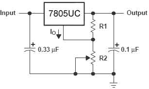
fig. 3. Typical scheme with fixed voltage and fig.4. Adjustable scheme
Typical connection diagram is displayed in Fig.3. Adjustable option in Fig.4

Fig.5
Power supply based on 7805UC Fig.5. We need a lowering transformer TP1 to 7..25V with output current 1-1.5a. High voltage switch (1a) and fuse 0.5A. For diode Bridge I recommend using 4 diodes KD226A, each is designed for 2a, fault tolerant. Condensors C1 and C2 electrolyte for voltage 15V. C1 100MKFH15V The primary filter compensates for the pulse voltage jumps from the transformer. The stabilizer can greatly warm and need to install the radiator, which will dispel the excess heat (the more, the better).
In this article, we will consider the possibilities and ways to supply digital devices collected by their own hands, in particular on. It is no secret to anyone that the key to the successful operation of any device is its proper submission. Of course, the power supply must be able to produce power required to power the device, have a high capacity electrolytic capacitor at the output, to smooth the pulsations and it is desirable to be stabilized.
The last underscore, especially, different unstabilized power supplies type of chargers from cell phones, routers and similar techniques are not suitable for powering microcontrollers and other digital devices directly. Since the voltage at the output of such power supplies varies, depending on the power of the connected load. The exception is the stabilized chargers, with uSB output, outstanding at the exit of 5 volts, such as charging from smartphones.

Many beginners to study electronics, and just interested, I think shocked the fact: on the power adapter, for example, from the console Dandy, and any other similar unstabilized can be written 9 volts DC (or d.C.), and when measuring the Multimeter, connected to the PC Plug Contacts on the Multimeter screen, all 14, or even 16. Such a power supply can be used if you want to power digital devices, but the stabilizer is collected on the 7805 chip, or roll5. Below in the photo of the L7805CV chip in the Case-220 case.

Such a stabilizer has a slight connection scheme, from the bonding of the chip, that is, from those parts that are necessary for its work, we require only 2 ceramic capacitors by 0.33 μF and 0.1 μF. Connection diagram Many are known and taken from datashet on the chip:

Accordingly, we supply voltage to the input of such a stabilizer, or connect it with a plus of the power supply. And minus connect with a minus chip, and we feed directly to the output.

And we get at the output required to us the stable 5 volts, to which if you wish, if you make the appropriate connector, you can connect uSB cable And charge the phone, MP3 player or any other device with the possibility of charge from USB port.

Stabilizer decrease from 12 to 5 volts - diagram
Automotive charger With the USB output, everyone has long been known. Inside it is arranged on the same principle, that is, the stabilizer, 2 condenser and 2 connector.

As an example for those who wanted to collect similar charging with their own hands or repair the existing will bring its scheme, complemented by the inclusion indication on the LED:

COCOLOGY 7805 chip in the T-220 housing is shown on the following figures. When assembling, it should be remembered that the cessing in the microcircuits in different buildings is different:


When buying a microcircuit in a radio shop, a stabilizer should be asked as L7805CV in the Case-220 case. This microcircuit may operate without a radiator at a current of up to 1 amp. If required for high currents, the chip must be installed on the radiator.

Of course, this microcircuit also exists in other cases, for example, TO-92, familiar to everyone on low-power transistors. This stabilizer works at currents up to 100 milliam. The minimum stress at the inlet, in which the stabilizer begins to work, is 6.7 volts, standard from 7 volts. The photo of the chip in the Case-92 is shown below:

COCOLOGY OF THE CHOCKET, IN THE CASE OF TO-92, as already written above, differs from the CCOs of the chip in the Corps of TU-220. We can see it in the following figure, how it becomes clear from it that the legs are located mirror, relative to-220:

Of course, stabilizers are produced on different voltage, for example 12 volts, 3.3 volts and others. The main thing is not to forget that the input voltage must be at least 1.7 - 3 volts larger than the output.

Microcircuit 7833 - Scheme
The following figure shows the base of the 7833 stabilizer in the TO-92 housing. Such stabilizers are used to be powered in devices on microcontrollers of displays, memory cards and other peripherals requiring lower-gas nutrition than 5 volts, the main power supply of the microcontroller.

Stabilizer for power MK
I use to be powered by the devices collected and debugged on the macateboard on the microcontrollers, the stabilizer in the housing, as in the photo above. Power is supplied from an unstabilized adapter through the socket on the device board. Its schematic diagram is shown in Figure Next:

When the chip is connected, it is necessary to strictly correspond to the COF. If the legs confuse, even one inclusion is enough to derive the stabilizer, so that when you turn on, you need to be attentive. The author of the material is AKV.
This small article is devoted to a three-way stabilizer. voltage L7805. The microcircuit is produced in two types, in plastic - TO-220 and Metal - TO-3. Three conclusions, to watch left to right - input, minus, exit.
The last two digits indicate the stabilized voltage microcircuits- 7805-5 volts, respectively, 7806-6V .... 7824-probably already guess how much. You may also be interested in vests for the choir boys, more on the site on the link.
Here connection scheme stabilizerwhich is suitable for all chips in this series:

We do not look at the capacitors of low capacity, it is advisable to put more.
Well, this is a stabilizer from the inside:

To go nuts, yes? And all this is placed ..... Whole technique.
So, we are interested in these characteristics. OUTPUT Voltage - output voltage. INPUT Voltage - input voltage. We are looking for our 7805. He gives us a 5 volt output voltage. The desired input voltage manufacturers noted 10 volts voltage. But it happens that the outlet stabilized voltage sometimes sometimes or slightly underestimated, or a little overpriced. For electronic baubles, the share of the volt is not felt, but for the desistence (accurate) instrument, it is better to collect their schemes. Here we see that the 7805 stabilizer can give us one of the voltages of the range of 4.75 - 5.25 volts, but the conditions must be observed (Conditions) that the current at the output in the load will not exceed one amp. Unstabilized constant pressure It can "break" in the range from 7.5 and to 20 volts, with this at the output will always be 5 volts. This is the big plus stabilizers.
With a large load, and this chip is able to give power as much as 15 watts, the stub is better to provide the radiator and, if possible, or by want, for greater and fast cooling, touch him the cooler, as in the computer.
Here is a normal stabilizer scheme:

Technical specifications
Case ... to-220
Maximum load current, and ... 1.5
Range of permissible input voltages, in ... 40
Output voltage, in ... 5
to help.
In order for the stabilizer to not overheat, you need to stick to the desired minimum voltage at the input of the chip, that is, if we have L7805, then on the entrance, let 7-8 volts, if 12 - 14-15 volts.
This is due to the fact that the excess power of the stabilizer will dispel on himself. How do you remember the power formula p \u003d Iu, where U is the voltage, and I is the current strength. Consequently, the larger the input voltage of the stabilizer, the greater the power consumed by it. And excessive power is heating. As a result of heating, such a stabilizer can overheat and enter the protection state, in which the further operation of the stabilizer stops.
 How to pay a domain name
 Domain zone of tokelau islands
 What is domain what problems may be
 Yandex Wordstat: detailed instructions for using the service and grouping operators and a complicated request
 Editing DBF files
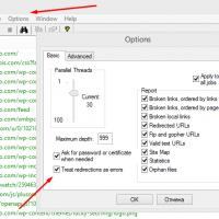 Xenu Link Sleuth - What is this program how to use the Xenu program
 Methods Copy and insert text from keyboard without using mouse