How to repair a charger. We disassemble the charger from the Siemens mobile phone. Charging Repair: Stages

The voltage on the battery was about 3.1 volts, which is less than the threshold, after which some chargers identify the battery and start charging it. In any case, this is how it was the case with my Battery from BlackBerry, which was discharged too deep.

The LI-12B battery managed to return to life by charged with a small current, about 100 mA. For this, a simple scheme was collected. When the voltage on the battery reached 4.2 volts, I stopped the charge and checked the camera's performance. The camera earned and I began to think about how to repair the charging. https: // Site /
Repair of the Li-10C charger.

That's how the charger was looking for me.

To disassemble the Li-10C charger, it took to unscrew the two screw screws, one of which was under the sticker.
Checking the work of the charger revealed the presence of short-circuited turns in the separation transformer of the pulse power supply unit.

The pulse transformer was unreprofitable, besides, I did not have a suitable ferrite core so that you could wind the new transformer.
In the picture, the printed circuit board of the charger. The arrow marked the DS-4207 transformer KT04044.

I decided, it was already going to go after the weekend to our radio link, but then I remembered that I have a fee from pasty charging for a mobile phone.

Charging this, bought it once in a faulty state for the sake of the body-fork, so that the power supply unit for the radiotelephone can be placed in it, which once designed for a 120 volt network voltage.
To check the transformer I had to first draw the scheme, and then replace all the burnt parts.
To my joy, the transformer turned out to be good, and in dimensions, it seemed to be just right.
Actually, the entire further repair was to replace the transformer.

If you look at the model switching on the driver of the PWM driver of this charger FSDH0165, then it can be noted that the transformer from the circuit is higher, it is functionally different from the burnt.
In total, people have problems with the failure of the charger, which involves the unpleasant consequences, as it becomes the impossible charging of the phone, if there is no other alternative to the charger. In today's article, we will look at all kinds of breakdowns and repair of the charger.
And so, to begin with, we define the main reasons for the failure of the charger, it may be:
- Breaking device feeding device;
- Damage to the charger block;
- Break contacts, connections or wires in plug or power supply;
Most often, the cause of the failure of the charger is to break the internal wires or damage to the connections between the plug or block. In such cases, the device can be attributed to the service centers or repaired independently. In this article, we will consider the second option, as an example, we will use a charger with a thin plug from Nokia.
To repair the charger, we will need:
- Normal multimeter;
- Knife for cutting wires;
- Soldering iron and solders;
- Electrical tape and shrink tube, if it is in stock;
- Motor thin copper wire for connecting contacts or damaged parts;
The first to which we will proceed are to search for damage in the wire or contact connections. Determine the place where the wire rupture occurred is quite easy, it contributes to a non-standard color or smaller diameter of the wire itself.
If visually could not determine the location of the gap, then the damage may not be damaged by the wire, but the connection defect between the device unit or the charging plug.
Start repairing a charger. First of all, cut off the wire in the area of \u200b\u200b7-10 cm from the plug, if the gap does not find it, we will be able to back to connect the plug to the power supply. Therefore, it is not desirable to cut off the wire close to the plug or power supply, since after which we can not turn it back.
Next, we clean the insulation wire (the one that is from the power supply). We take the multimeter and set the maximum allowable voltage up to 20V. (More on how to use a multimeter can learn c). Connect the contacts of the multimeter to the torn and cleaned wires and insert the charger to the network.
If the multimeter shows any value, it means damage in the power supply and no wire. In our case, the multimeter showed 7B - this means that the power supply is working properly, since the nominal output voltage of the device is equal to the same value.
We proceed the same action with the plug of the charger. We clean the wire from insulation and insert a thin wire into the inner part of the contact wire, it will be needed for accurate measurement by the multimeter of the nominal value of the plug.
In the multimeter, choose the transverse mode and touch one end of the probe to one of the protected wires, and the other first to the plug, then to the liner inserted. If the multimeter is a beep, it will mean that the voltage between the plug and the wire is also available and that the plug itself is correct.
If the device has not issued a sound alert, then it follows that the plug is faulty and in its contacts may have damage. In such cases, you can contact the store and buy a new charger or replace only the plug, but you can repair it and repaired than we now and do it.
If you have a different serviceable plug, you can replace it, just pulling it to the old power supply, while it is important to observe the polarity, for this there is a color marking on each cord, all wires are required to solder on the appropriate colors.
But sometimes it happens that the color marking is absent, in such cases you need to turn on the charger to the network, and the new plug to the phone. Next, you need to attach all the plug wires to the wiring block. If the phone goes into charging mode, you did everything right. If not, change wire connections until the phone does not switch to charging mode.
After that, we proceed to the soldering. If you have a heat shrink tube, then before soldering, we wear it to one of the wires, after which we solder both ends, by observing the polarity, after which you wind the connection place with a tape and again wear a heat shrinking tube.
But in case you have no additional plug, then you will have to repair the old one. To do this, you will need to gently remove the rubber coating with a knife from the old plug, while trying not to damage the connections of the plural itself.
After that, check the performance of the plug. Turn on the charger to the network and attach the cord to the phone. If everything works, insulate all the connections and attach to the plug a heat shrink tube. After that, the charger is ready to operate.
But it happens that when cutting the wires and voltage checks, it has emerged that it is missing, then in this case it will also have to cut the wire opposite the charging unit, retreating approximately 7-10 cm. It is required to protect against damage the wire leaving the power supply, after which you need to measure the presence of the output voltage. If the voltage is available, this indicates the health of the charging unit.
In our case, it was revealed that one conductor plug was broken. Visually it is difficult to identify. The optimal option may be the purchase of a new wire and a savage of it instead of the old one.
In this case, the polarity should also be observed, as well as before soldering, check the contacts of the wires, turning on the charger to the network, and the plug to the phone. If the phone began to accumulate charging, then you can proceed to the solder of the wires, and then insulate them.
If the wire and the plug of the charger are working, then the damage is likely to be in the charging block. Perhaps the problem may be in the break of contacts inside the charger. To correct damage, you need to disassemble the charger block and check all the wires and contacts for the presence of a break. If everything is in order with them, the problem consists in the block of the charger. At the same time, without possessing electrical skills, you will not be able to fix the charging unit. In this case, you will have to buy a new charger or attribute the old center to the service center.
Charger for lithium batteries do it yourself How to make a simple turn bank with your own hands: Scheme of homemade Power Bank
Now, more than ever, the number of gadgets per person has reached the maximum value.
Phones, tablets, laptops, different wireless headsets - all this abundance of technology has a power supply and, accordingly, a charger to it.
The phone is not charging from the charger - what to do?
Often, charging takes with you in a bag or pocket, and that they occupy a minimum of space, their cords twist with the inflection and stretch.
This in turn leads to a practically imperceptible eye of the wiring of the wire and the inoperability of charging. Just clip in cord - This is the most common breakdown in such types of devices, and throw it out because of this, to be honest, sorry.
Yes, you can certainly buy a new one and not to suffer, but if the device is non-standard, for example, the phone of the old model, then it is not always possible to find such charging. And on the "flea market" you can slip the block with the same problem, and no one needs extra spending.
Therefore, the repair of the charger is a matter of useful and worthwhile.
How to fix the charger for the phone, smartphone, tablet do it yourself
Below, in this article will be described simple and does not require special equipment to repair, which will give your charging the second life.
In the photo - charging with the problem in the cord.
Not always the opening is visible to the naked eye. It can be hidden under the thickness of the main (top) isolation and remains almost impaired.
But, as practice shows, the fracture occurs most often near the entrance to the block or at the base of the plug.
To detect the breakdown, it is enough to connect the charging to the phone and move the cord in a suspicious place.
As soon as you see that charging for a moment "went," means in the place where you at this moment moved, and there is a break.
In this case, looking attentively, the breakdown and the cliff were visible without moving. It just turned out at the input to the power supply.

The main problem in repairing such blocks is that it is not collapsible. Therefore, to get to the electronic board, you need to show accuracy and some efforts.
Using a screwdriver and knife, it is necessary to pose the base of the back cover and remove it.

It follows in the place of the cord input to the device. If the input is too dense, you can cut the rubber clamp slightly.

It is necessary to do it carefully to do not cut the wire at all.
Steaming a screwdriver, trying to raise the cover up.

It may happen that it will crack in the pressure, but more often, as in this case, the lid has taken off entirely, without damage.

It was even seen that she had latches, and in the case of the charging device of the excavation for them.
This means that there is an opportunity after repair to put the lid in its place without using glue.
When the lid is removed, you need to pull the circuit board from the case. Since she "sits" tightly, a screwdriver will help. Supervised the blade screwdriver about the body and hooking it with the end of the soldering, pull out the feet out.


The body of the housing is that when the board inserted inside the board, its input contacts are connected to the pins of the power plug. Therefore, by installing a fee back into the housing, you need to take into account this moment.
The photo below shows the board with all its "entrails". The wires are soldered below.

View from the opposite side.

But in the photo tracks for entrance contacts.

The wire will have to trim below the place where damage is located. But it is very important to remember which wire "+", and what "-". In some cases, the wires have an appropriate color, the red is positive, and a black is a negative conductor.
When color marking, cut can be trimmed, and after just soldering wires, observing the polarity.
In our case, the wires are monochrome, but since the cord is flat, you can trace, from which side of the cord is the wire for minus, and with what a plus. Mark, well, and then cut.


Without losing tags, clean and fill the wires on the cord.

For one we solder them to the board, observing the polarity.


On the printed circuit board at the site of the soldering usually there is a marking of polarity.

So that the cord at the outlet dangle, we wind up the bandage from the black tape into its inlet part. The thickness of the bandage should be so to enter the slot for the wire and fix it in it.


Before installing the cover, check the operation of the device. Include it in the network and connect to the phone. If there is no phone at the moment with yourself, we use the DC voltmeter.
Since internal contact in the nest has a very thin tube, and the appliance probent does not enter it, you can use a piece of thin copper wire for checking.

Lowing it into the internal contact tube, connect to it and the outer conclusion of the plug of the probe of the measuring device.
A voltmeter shows that the voltage is present, which means that the breakage is eliminated.

Now you snap the back cover.

Connect the phone and rejoice in the results of the work done.

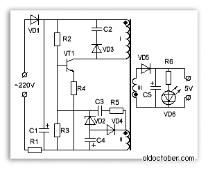
Greetings of radio amateurs !!! Riding old fees came across a couple of pulsed power supplies from mobile phones and wanted to restore them and at the same time tell you about the most frequent breakdowns and troubleshooting. The photo shows two universal schemes of such charging, which most often meet:

In my case, the board was similar to the first scheme, but without a LED at the output, which plays only the role of the voltage presence indicator at the outlet of the block. First of all, you need to deal with the breakdown, below in the photo I'm out of question what the most often fails:

And we will check all the necessary parts using the usual multimeter DT9208A. It has everything you need for it. The mode of sounds of diodes and transition transitions, as well as an ohmmeter and a meter of capacitor capacitance to 200μF. This set of functions is more than enough.

During the inspection of radio components, it is necessary to know the base of all parts of the transistors and diodes especially:


Now we are fully prepared for checking and repairing a pulse power supply. I will finally check the block to identify visible damage, in my case there were two burnt resistors with cracks on the case. More explicit disadvantages did not reveal, in other power units met swollen capacitors to which it is also necessary to pay attention in the first place !!! Some details can be checked without supply, but if you doubt it is better to fall and check separately from the scheme. Okay do neat so as not to damage the tracks. Conveniently in the process of soldering to use the third hand:

After checking and replacing all faulty parts, do the first inclusion through the light bulb, I made a special stand for this:

Turn on the charger via the light bulb if everything works, then spin in the housing and rejoice in the work done, but if you do not work out other disadvantages, also after the soldering, do not forget to wash the flux, for example alcohol. If nothing helped and the nerves in the balance thump or squint and reflect live parts into the reserve. Good mood to all. I propose to watch a video.
Very often, the vehicle breakdowns are so elementary, and easily disposable, that sometimes you don't even want to take for repair, it does not represent interest, but you have to. Recently, I turned to me for the help of my friend, so who lived to it is not good, and recently, due to the crisis, also lost work.
Shows a universal charger type Frog For lithium battery from phones, with bullshit fasteners of the pressed part, and asks whether it is possible to do anything. He says that they sat down. The first thought was, to offer him to throw away, and buy a new one, but looking at his distressed broken face - changed his mind and decided to help.

In stock There were two new crocodiles in the insulation, only the tip was turned out, and it was decided to fall to the wires going to the mustaches, and to the battery connect crocodiles. He stuck the charger in the outlet to make sure that it works at all, and my works will not be in vain, and began to disassemble.

First, 2 screws were unscrewed, fastening the mustache to the pressed battery part, the mustache were integer. Often, when working, these mustache is laid out, and it becomes impossible to use it, so the mustache left itself about the reserve. If someone does not know how to use such a charger, I will explain: we take a lithium ion battery, from a cell phone, a camera and other similar technique. We combine the charging mustache, with its contacts plus and minus, they are signed on the battery, and press the battery to the charging case, due to the spring of the pressed part. The LED should light up on the charger, showing that there is a contact between the beaches and the battery contacts. For those who may need to be able to send a similar charger, with a more serious breakdown, I will give one of the options for the concept:
Charging scheme

Let's return to our repair, reloading two screws, disassembled the frog body. It remained to determine which of these wiring, which goes to the mustaches plus, and what minus. Such a check is quite conditional, because there is on such charging devices, or the automatic determination of polarity, and then the buttons are missing, or there is a ignition button.

But still, I wanted to collect so that the red dipstick was a plus, and a black minus. Then he took off the board and found a shared wire connected to one of the wiring, it was connected to the Polygon on the board. It was decided to consider it for minus. Further the case, we needed beautiful wires, for connecting with wiring, going from the mustache. I just had such wiring from the dynamics of the computer. The speaker itself and the connector were cut off, the wiring length decided to take sufficient, for convenient connection to the battery contacts.

Recently, I have a habit of watching the aesthetics of the connections in the device, it does not matter, do myself or people, for money or for purely symbolic gratitude. Therefore, he bought heavow shrimp with a margin, different diameters, for all occasions, and decided to abandon snot on connections in the form of a tape. Which, by the way, is not enough that it looks ugly, also strives with time to break off the connections of the wires and talk it. What is it fraught, I think to explain to anyone you do not need.

So here also, before the soldering of the wires, two pieces of heat shrinking were put on the wires, and after the soldering began the lighters on fire. It turned out beautiful reliable insulation. By the way in the West, if you judge the insulation of LEDs and buttons, computers' enclosures, have long abandoned the use of the tape, and pack all that remains for long-term use, only in the heat shrink. Before soldering wires, the habit has tied the wire by a node, in order to be impossible, applying the effort to cut the wires. Make it, will not allow just a node, the size of which is greater than the hole in which the wire is missed in the charger case.

It remains only to assemble the charger in the case and test, turning on the network, and connecting crocodiles with battery contacts. Everything worked as it should have blinking the LED showing that the battery was charging. And as it turned out, with the polarity and color of crocodiles, when the wires are sweeping, I was not mistaken. All successful repairs! The author of the article is AKV.
 Magnetometry in the simplest version The ferrozond consists of a ferromagnetic core and two coils on it
 Effective job search course search
 The main characteristics and parameters of the photodiode
 How to edit PDF (five applications to change PDF files) How to delete individual pages from PDF
 Why the fired program window is long unfolded?
 DXF2TXT - export and translation of the text from AutoCAD to display a dwg traffic point in TXT
 What to do if the mouse cursor disappears