A computer power supply provides an overestimated voltage. Common power supply faults
The power supply fails quite often, this is especially true of the work blocks of work. The worst thing is that sometimes breakdown this device entails the failure of almost all installed components, especially if the motherboard is deprived necessary protection - power stabilizers.
The most common are the following faults that are subject to the power supply.
- Unstable alternating voltage. A variable voltage source for the power supply is an external variable voltage network. Unfortunately, the quality of this tension in the CIS countries is extremely low. The "normal" phenomenon is the value of the voltage and 180, and 200, and even 260 V, while desirable is the voltage in the range of 210-230 V. The entire punch is received by the input circuits of the power supply chains, and if the quality of the components of these chains is located At a low level, the power supply is either overheated, or generally fails.
- Low quality electronic components. The number of electronic component manufacturers is growing every day, but, unfortunately, it does not affect the quality of these components. As a result, the power supply is extremely dependent on the operation of these components, which, in turn, affects its service life.
- User actions. Often the reason for the malfunction becomes the "Started" user, which, contrary to common sense, is trying to reduce the noise of the power supply fan with a reduced voltage to it, while the temperature inside the power supply is at a critical level. In addition, few people think about to purchase a source uninterrupted power And protect yourself from problems associated with sharp voltage jumps that the power supply takes very painful.
- Increased moisture level. Condensate penetrates B. electronic circuit Power supply, from which transformers, chokes and other components containing wire winding are most. Humidity makes adjustments to the resistance of such components, which in the case of sufficiently frequent voltage jumps leads to excessive load on them. Accordingly, as a result, the time of their operation is sharply reduced, which can lead to partial or complete failure.
- Time and service life. Don't forget that any electronic components have a certain period of operation, which is also directly dependent on the conditions of their use. So, if you will always require such power from the power supply unit with a maximum power of 300 W, and sometimes even more, the component resource is quickly exhausted and the power supply will simply not be able to extradite more than the average power indicator.
- Exhausting internal resources. The most common and inevitable malfunction is the gradual depletion of the power supply resources and the drop in its power. The result of this effect is the unstable computer operation, frequent reboot or failure is turned on.
The power supply is not a device that cannot be repaired: many of the faults can be eliminated and independently. However, before this is done, it is worth understanding that the operation of all other devices depends on the power supply unit, so irresponsible actions during troubleshooting expose these devices to a lot of risk.
Tip !!! In most cases, the repair of the power supply does not give the expected effect or gives, but on a completely short time. Therefore, I advise you to immediately purchase a new power supply, while choosing a time-tested model.
So, they were allowed to repair the power supply unit POWER MAN by 350 watts
What are you doing first? External and internal inspection. We look at the "loss". If what burned radio elements? Maybe somewhere charred or the capacitor exploded, or smells like burner silicon? All this take into account when inspection. Be sure to look at the fuse. If he burned down, then we put a temporary jumper instead about the same amp, and then measure two network wires. This can be done on the plug of the power supply when the "On" button is turned on. It should not be too small, otherwise, when the power supply is turned on, it will happen again.
We measure tension
If everything is ok, we turn on our power supply to the network using network cablewhich goes along with the power supply, and do not forget about the power button, if it was in the off state.


My patient on a purple wire showed 0 volts. I take and ring the violet wire on the ground. Earth is a black wire with the inscription COM. COM - abbreviated from "Common", which means "common". There are also some types of "lands":


As soon as I touched the earth and purple wire, my multimeter issued a subsidian "PIIIIIIIIIIIIP" signal and showed zeros on the display. Short circuit , definitely.
Well, we will look for a scheme for this power supply. Google through the spaces of the Internet, I found a scheme. But I found only on Power Man 300 watts. They will still look like. Differences in the scheme were only in the ordinal numbers of radio components on the board. If you can analyze pCB For compliance with the scheme, it will not be a big problem.
And here is the scheme on Power Man 300W. Click on it to enlarge in natural size.

We are looking for the culprit
As we see in the scheme, duty nutrition, then on the text - duty, is indicated as + 5VSB:

Right away from her stabilirton Rate of 6.3 volts to Earth. And how do you remember, Stabilong is the same diode But connects in circuits on the contrary. Stabitron uses the reverse branch Wah . If Stabilitron had been alive, then we would have a wire + 5VSB would not be corobor. Most likely Stabilitron burned down and destroyed.
What happens when combustion of different radio components from a physical point of view? First, they change them resistance . In resistors, it becomes infinite, or in other words, goes into a break. In capacitors it sometimes becomes very small, or in other words, goes into short circuit. With semiconductors, both of these options are possible, both short circuit and a break.
In our case, we can check it only in one way, dropping one or immediately both legs of Stabilon, as the most likely short-circuit perpetrator. Next, we will check whether the short circuit has disappeared between duty and weighing or not. Why is this happening?
Remember Simple Tips:
1) for sequential connection It works more than more, in other words, the total chain resistance is larger than the resistance of more from the resistors.
2) With the parallel connection, the opposite rule works, less smaller, in other words, the final resistance will be less than the resistor resistance of smaller from the denominations.
You can take arbitrary resistance values \u200b\u200bof resistors, independently calculate and make sure that. Let's try to logically think if we have one of the resistance parallel to the connected radio components will be zero, what indications will we see on the multimeter screen? Right, also equal to zero ...
And as long as we are not eliminated, this short circuit by falling out one of the legs of the part, which we consider problem, we will not be able to determine which details we have a short circuit. The thing is that with a sound nozzle, all the details are parallel to the detail of the short circuit, will be ringing with a shared wire!
We try to drop the stabilion. As soon as I touched it, he fell apart. No comments…

It's not about Stabilion
We check whether we have a short circuit through the chains of duty and mass, or not. Indeed, short circuit was gone. I went to Radomagazine for the new Stabilon and sealed it. I turn on the power supply, and ... I see how my new, just purchased Stabilong emits the magic smoke) ...
And then I immediately remembered one of the main rules of the repairman:
If something burned down, find the reason for this, and only then change the item to a new or risk of getting another burnt item.
Speaking about yourself with a mat, snacking burnt stabilion by rake and turn on the power supply again.
So there is digeon overestimated: 8.5 volts. The main question is spinning in the head: "Are the controller still live, or did I burn it safely?". Downloading datashet on the chip and see the limit supply voltage for the PWM controller, equal to 16 volts. Uff, it seems to carry ...

Checking condensers
I begin to google my problem on special sites dedicated to the repair of BP ATX. And of course, the problem of the overestimated strain of duty is in a banal increase. ESR. Electrolytic capacitors in the chains of duty. We are looking for these condensers in the diagram and check them.
I remember your assembled device Esr meter

It's time to check what it is capable of.
I check the first capacitor in the duty chain.


ESR within the normal range.
We find the culprit of the problem
Checking the second


Waiting, when a value appears on the multimeter screen, but nothing has changed.

I understand that the culprit, or at least one of the perpetrators of the problem is found. Cutting the capacitor to exactly the same, at face value and working voltage taken from the donor board of the power supply. Here I want to stop more:
If you decide to put in the block aTX power supply The electrolytic capacitor is not from the donor, but a new one, from the store, be sure to buy LOW ESR capacitors, and not ordinary. Ordinary capacitors do not work well in high-frequency circuits, and in the power supply, just such chains.
So, I turn on the power supply and re-measuring the tension on the duty room. Scientific bitter experience is no longer hurry to put a new protective stabilion and measure the tension on duty, relative to the Earth. Voltage 12 volts and a high frequency whistle is distributed.
Again I sit down to google on the problem of overestimated tension on duty, and on the site rOM.BY.devoted to both the repair of ATX BP and motherboards and in general the entire computer iron. I find my fault by searching in typical faults This power supply. Replaced to replace the capacitor with a capacity of 10 μF.
I measure ESR on the condenser .... Ass.


Result, as in the first case: The device is rapid. Some say, they say why collect some devices, such as the discarded non-working capacitors, so can be seen - they are swimming, or shouted with romel
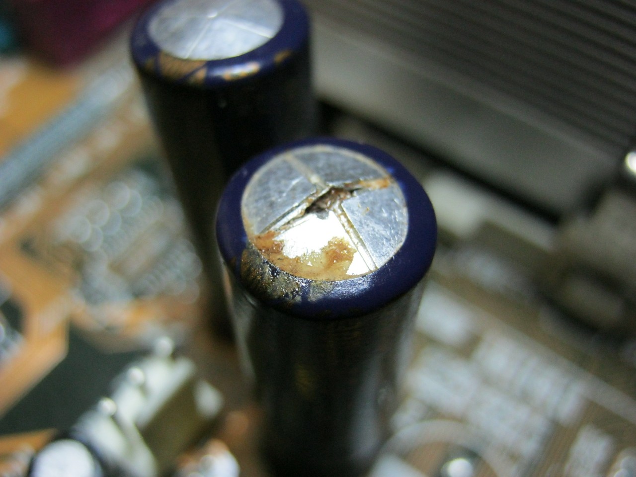
Yes, I agree with this. But this applies only to the capacitors of a large nominal. Capacitors relative to small denominations do not swell. In their top there are no notches for which they could reveal. Therefore, they are simply impossible to determine visually on operability. It remains only to change them on knowingly workers.
So, the second condenser I needed my fees on one of the donor boards was found. Just in case it was measured by ESR. It turned out to be normal. After putting the second capacitor in the fee, I turn on the power supply with a key switch and measure the duty voltage. What was required by 5,02 volts ... Hurray!
I measure all other voltages on the power supply connector. All correspond to the norm. Deviations of operating stresses less than 5%. Stabilion remains 6.3 volts. I thought for a long time why the stabilion was exactly 6.3 volts, when the duty tension is +5 volts? It would be more logical to put on 5.5 volts or similar if it were stood to stabilize the tension on the duty room. Most likely, this stabilion stands here as a protective, in order to increase the voltage on the duty, above 6.3 volts, it burned down and closed the spice chain of the digeon, thereby turning off the power supply and retaining our motherboard From combustion when an overpriced voltage is received over the duty officer.
The second function of this stabilion, see, protect the PWM controller from the inflated voltage on it. Since the duty room is connected to the meal of the chip through a fairly low-level resistor, therefore, on the 20th leg of the power of the PWM chip, almost the same voltage comes, which is present in our duty.
Conclusion
So, what conclusions from this repair can be draw:
1) All parallel connected parts during measurement affect each other. Their values \u200b\u200bof active resistance are considered according to the rule of parallel compound of resistors. In the case of a short circuit on one of the parallel connected radio components, the same short circuit will be on all other parts that are connected in parallel.
2) To identify faulty capacitors of one visual inspection, it is not necessary to either change all faulty electrolytic capacitors in the chains of the device's problem node on knowingly workers, or to be rejected by measuring the ESR-meter instrument.
3) Finding some kind of burnt item, do not rush to change it to a new one, and we are looking for a reason that led to its combustion, otherwise we risk getting another burnt item.
We looked at what actions need to be taken if we have an ATX power supply fuse in a short circuit. This means that the problem is somewhere in the high-voltage part, and we need to nick diode bridge, output transistors, power transistor or mosphores, depending on the power supply model. If the fuse is intact, we can try to connect the power cord to the power supply, and turn on its power switch located on the rear wall of the power supply.
And here we can wait a surprise, as soon as we clicked the switch, we can hear a high-frequency whistle, sometimes loud, sometimes quiet. So, if you heard this whistle, do not even attempt to connect the power supply for the tests to the motherboard, assembly, or install such a power supply into the system unit!

The fact is that in the chains of the duty voltage (digeon), there are all the same electrolytic capacitors, which lose the container, with heating, and from old age, they increase ESR, (in Russian abbreviated EPS) is equivalent serial resistance. At the same time visually, these capacitors may not differ from the workers, especially for small denominations.


The fact is that on small nominees, manufacturers very rarely suite notches at the top of the electrolytic capacitor, and they do not swell and do not open. Such a capacitor does not measure the special device, it is impossible to determine the suitability of work in the scheme. Although sometimes, after druising, we see that the gray band on the condenser, which marks the minus on the capacitor body, becomes dark, almost black from heating. As the repair statistics shows, there is a power semiconductor, or the output transistor, or a diode diode, or mosphores next to such a capacitor. All these parts are highlighted with heat, which adversely affects the operation of electrolytic capacitors. Further explain about the performance of such a darkened capacitor, I think it will be superfluous.

If the power supply has stopped the cooler, due to drying the lubricant and scoring with dust, such a power supply will most likely require the replacement of almost all electrolytic capacitors to new, due to elevated temperatures inside the power supply. Repairs will be quite vigorous, and not always appropriate. Below is one of the common schemes on which the power blocks of PowerMan 300-350 watts are based, it is clickable:
Scheme BP ATH POWERMAN
Let's wonder what condensers need to be changed in this scheme, in case of problems with duty:

So, why do we not connect the power supply with a whistle to assemble for tests? The fact is that there are one electrolytic capacitor in the duty chains, (highlighted in blue) with an increase in the ESR of which, we increase the duty voltage issued by the power supply unit to the motherboard, even before we press the power button system Block. In other words, as soon as we clicked the keyboard switch on the back of the power supply wall, this voltage that should be +5 volts, enters the power supply connector, the purple wire 20 PIN connector, and from there to the computer motherboard.

In my practice there were cases when the duty voltage was equal to (after removing the protective stabilion, which was in the KZ) +8 volts, and at the same time the PWM controller was alive. Fortunately, the power supply was high-quality, the Powerman brand, and there stood on the + 5VSB line, (it is designated in the diagrams of the duty room) protective stabilion by 6.2 volts.

Why is Stabilong protective, how does it work in our case? When the voltage is less than 6.2 volts, the stabilong does not affect the operation of the scheme, if the voltage becomes higher than 6.2 volts, our stabilion goes to the KZ (short circuit), and connects the chain of the home digeon. What gives us this? The fact is that by closing the duty on the ground, we keep our motherboard from filing the most 8 volts to it, or another value of high voltage, along the duty room on the motherboard, and protect the motherboard from burnout.

But it is not 100% chance that in the case of problems with capacitors, Stabilirton will burn, there is a chance, although it is not very high that it will go into a break, and thereby protects our motherboard. In cheap power blocks, this stabilion usually simply do not put. By the way, if you see the traces of the burnt textolite on the board, know, most likely there, some semiconductor went into a short circuit, and it was very long for a very long current, such a part is very often and is the reason (though sometimes it happens as a consequence) breakdowns.

After the tension on the duty officer comes to normal, be sure to change both capacitors at the outlet of the duty. They may be in disrepair due to the feed voltage on them exceeding their nominal. Usually there are capacitors of the nominal 470-1000 μF. If after replacing the capacitors, we have a +5 volt voltage on the ground, we can close the green wire with black, PS-ON and GND, running the power supply, without motherboard.

If the cooler starts to rotate, it means with a large share of the likelihood that all the voltages within the norm, because the power supply has started. The next step, you need to make sure that the stress on the gray wire, Power Good (PG), relative to the Earth. If there is a +5 volt there, you are lucky, and it remains only to measure the multimeter of the voltage, on the connector of the power supply unit 20 PIN to make sure that none of them get a lot.

As can be seen from the table, the tolerance for +3.3, +5, +12 volts - 5%, for -5, -12 volts - 10%. If the duty room is normal, but the power supply does not start, Power Good (PG) +5 volts we do not have, and on the gray wire relative to the ground zolt, then the problem was deeper than only with duty. Various breakdown and diagnostic options in such cases, we will consider in the following articles. All successful repairs! With you was AKV.
 Causes of why Flash Player does not work, and troubleshooting
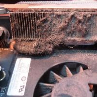 The laptop itself turns off, what to do?
 HP Pavilion DV6: Characteristics and Reviews
 Format representation of a floating point numbers How negative numbers are stored in the computer's memory
 Computer fries and does not turn on what to do?
 Why does not work mouse on a laptop or mouse?
 How to increase or decrease the scale of the page (font) in classmates?