Cohesion of phases definition. Phase control relay. Choice of protection device
Classic disadvantages of the EL series phase control relays
"News of Electrical Engineering" №5(29) 2004
The problem of protecting electrical equipment from low-quality voltage in the network exists in almost any enterprise, especially when working from three-phase voltage sources. In addition to the decrease and increase in voltage on all three phases, the so-called “phase imbalance” is a significant danger - the case when the voltages on the phases have different values, which leads to overheating of the motor or transformer windings and their failure. Very often there is a break in one phase.
In many cases, for the normal operation of the equipment, a strictly defined sequence of phases of the supply voltage is required. Sometimes, as a result of an accident in the power circuit, a situation may arise when all three phases have a voltage of 220 V relative to ground, but two of them are closed to each other (the so-called “sticking” of phases). Operation of the equipment at such a voltage will lead to its failure.
To protect equipment from such cases, a large number of different voltage monitoring relays (phase monitoring relays, voltage monitors) are produced.
The most common imported relays are SQZ3, C556, CM-PVN by ABB, TPW400VSN4X, TPF400S4X by TeleControl, EFN, PBN by Entrelec, etc.
The most widely used domestic phase control relays for operation in networks with isolated neutral are relays of the EL series - EL-11, EL-12 and EL-13. They were developed about 30 years ago by the Rhythm Design Bureau of the Kiev NPO Relay and Automation. Successfully chosen thresholds and a minimum of adjustments, as well as the complete absence of alternatives, contributed to the wide distribution of these relays. Almost unchanged, they are produced to this day.
Some factories produce these relays in their original form with all their advantages and disadvantages. Other companies offer improved models with digital signal processing, additional control functions, adjustments, and increased reliability.
Advantages of the EL relay
Relays EL-11, EL-12 and EL-13 are designed to control the full-phase mains voltage, phase sequence, voltage reduction and can be used in automatic control and protection circuits against unacceptable phase voltage asymmetry and operation on two phases.
Despite the huge selection of imported devices on the Russian market, the EL series relays remain popular primarily because of their low price, which is 20–25 USD. The minimum cost of a foreign-made relay is 50 USD, and the maximum is up to 250 USD, which, in the conditions of financial instability of many Russian industrial enterprises, is an obstacle to the use of imported products.
In addition, some foreign relays require a separate supply voltage for operation (the so-called “operational power supply” voltage), which complicates their connection scheme and limits the scope. In this case, the power supply of the EL series relay is carried out from a controlled network.
Another argument in favor of the use of domestic relays is the operating temperature range. For imported relays, it is rarely below minus 25 ° C, for ours, as a rule, it is up to minus 40 ° C. In Russian climatic conditions, this is an important factor.
Not always imported devices are designed to work in harsh conditions. For example, great difficulties arise in the control of mains voltage in the subway and railways. The movement of an electric train is accompanied by the appearance of a large number of non-linear distortions of the mains voltage in adjacent power networks (Fig. 1). The situation is no better in metallurgical production (Fig. 2). There have been cases when expensive imported control relays (even from well-known companies), when used in such networks, were unstable or simply refused to work. Domestic relays, originally designed for our networks, as a rule, work more stably in such conditions.
Rice. one |
Rice. 2 |
Identified shortcomings of the EL relay
Initially, all relays of the EL series had the disadvantage of high heat dissipation and, as a result, low reliability. With dense installation in a cabinet and poor ventilation, the relays quickly failed. So, for old Kiev relays for a voltage of 380 V, the power consumption at rated voltage was about 5 watts. Modern relays consume about 3 watts, and some even less than 2 watts, which has significantly increased their reliability.
Another significant drawback of all relays of the EL series with analog signal processing is the incorrect operation of the relay when switched on in emergency mode. Unfortunately, this is not reflected in the accompanying documentation of many manufacturing plants. Meanwhile, the relays give a false inclusion for a set delay time when a low or high voltage is applied to it. It would seem that this is a rather harmless situation. But, for example, when using such a relay on a circular knitting machine, an accident is inevitable, because even one or two seconds of rotation in the opposite direction is enough to break all the needles (from 500 to 2000 pieces, depending on the type of machine). Therefore, when operating such machines, they act in the old fashioned way: after connecting the machine or repairing the power cable, remove the drive belt, turn on the engine and look in which direction it rotates. Note that relays with digital signal processing are deprived of this disadvantage.
Here is a tragic example of the lack of a relay with analog signal processing. A tree fell on a power line and cut off two wires. The wires fell to the ground on top of each other, the so-called "sticking" of the phases occurred. Automation did not turn off the voltage and as a result a person died. The EL-11 relay was used as a protective relay. The electrical laboratory of the operating organization, which was in charge of the power transmission line, conducted comparative tests of the EL-11 relay from different manufacturers. The following results were obtained:
- when the relay was switched on at rated voltage, followed by imitation of various types of mains voltage failures specified in the accompanying documentation, all relays worked exactly in accordance with the documentation;
- when the relay is switched on at the rated voltage, followed by imitation of "sticking" of the phases (this situation is not specified in the documentation), the relays, except for devices with digital signal processing, in most cases do not turn off, which led to tragic consequences;
- when the relay is turned on for voltage with a broken phase, or the reverse order of the phase sequence, or when the phases are “stuck together”, or when the voltage is too low, all relays, except those produced by Meander CJSC, turn on the executive relay for the set delay time and only after that turn it off by detecting a mains voltage failure.
The outdated design of the EL series relay housing, the quality of the housing casting, and sometimes the housing material itself leave much to be desired. Therefore, some manufacturers have already mastered the production of relays in other cases, including imported ones.
EL relay applications
Despite the fact that all relays of the EL series control full-phase voltage, they have different areas of application: EL-11 is designed to control the voltage level, EL-12 - to control the order of phase sequence and voltage asymmetry (phase imbalance), EL-13 - for voltage unbalance control without interleaving control. Some areas of application:
The EL-11 relay is used to protect power supplies, generators, as well as control devices in ATS systems, etc.
Relay EL-12 is used to protect powerful asynchronous motors operating in non-reversible mode.
Unfortunately, in the documentation for this relay, most manufacturers indicate the response threshold when the voltage of one of the phases decreases at the rated voltage of the other two, which does not allow us to fully judge how the relay works. Experimentally, it was found that it actually works when the voltage asymmetry is more than 15–18%.
When one of the phases breaks, some types of motors generate voltage (so-called regenerative voltage) to the broken phase. The voltage amplitude can reach 95% of the voltage on other phases (depending on the type of motor and its operating conditions). Relays EL-12 with digital signal processing have an adjustment of the permissible value of asymmetry in the range from 5 to 20% of the linear voltage, which allows you to stop the engine in case of a phase failure. In this case, the relay will not respond to a symmetrical voltage drop when starting the engine. Another advantage of such relays is the presence of a minimum switching threshold. The relay will turn on only if the mains voltage is at least 70% of the nominal value. This is especially true for pump motors, compressors, etc., where the torque on the shaft does not depend on the rotational speed.
Relay EL-13 is used to protect powerful electric motors operating in reverse mode. Controlled parameters are practically the same as those of EL-12, except for the phase sequence control.
Relays are available with different response times - 0.1 s, 0.15 s and 0.5 s, as well as with delay adjustment from 0.1 to 10 s. These relays can be used to protect against falling loads and booms on cranes in the event of a break in one or two phases of the supply network. In accordance with the Rules for the Design and Safe Operation of Hoisting Cranes, these mechanisms must be equipped with control devices that ensure that the braking mode is activated in the event of a power failure. These requirements are met by the relay EL-13 manufactured by the Kiev "NPO Relay and Automation" and the Moscow LLC "Relay and Automation", EL-13M of the St. Petersburg CJSC "Plant STS", EL-13M-10-01 and EL-13M-11-01 "Meander". A relay with an extended response time (0.5 s) is used on cranes where a short-term power outage is possible when the current collector moves from one trolley to another to prevent false positives. To eliminate the human factor, it is not recommended to use relays with adjustable response time for these purposes.
There is also a modification of the relay with adjustment of the response time and adjustment of the threshold for voltage EL-13M-5-01. The response time controller allows you to set the desired value from 0.1 to 10 seconds to avoid false alarms in the presence of short-term disturbances in the network.
About new models
A few words about EL relay models with an extended set of functions. All relays manufactured by CJSC "Meander" have overvoltage control at the level of 1.3 Unom. Relays EL12M-5-01 and EL13M-5-01 additionally have a threshold for switching on the relay at a level of 0.7 Unom to protect electric motors from starting at low voltage, and relays EL12M-6-01 and EL13M-6-01 also have a delay of repeated switching on 6 min. These relays are designed to protect the motors of compressors, refrigerators, air conditioners, etc., where frequent restarts are undesirable.
In conclusion, I would like to note the following. The evolution of the EL series relays, namely:
- the use of modern microcontrollers with analog-to-digital signal processing;
- getting rid of congenital defects;
- the appearance of additional functions and adjustments,
- puts these relays in terms of their characteristics and reliability on a par with the control relays of world leaders, such as ABB, Siemens, Turk, Crouzet, etc.
table
Comparative characteristics of phase control relays from various manufacturers
Type |
Produc- |
Control |
Relay triggered |
(turns off) when: |
Mini- |
Time |
Zade- |
Consumed |
Spo- |
Maybe |
|||||
asim- |
one- |
symmet- |
one- |
reverse |
cliff |
slipa- |
|||||||||
| 100, 110, 220, 380, 400, 415 | ana- log- new |
||||||||||||||
| 100, 110, 220, 380, 400, 415 | ana- log- new |
||||||||||||||
| 100, 110, 220, 380, 400, 415 | ana- log- new |
||||||||||||||
EL11 M - 01 |
100, 110, 220, 380, 400, 415 | digital ro- howl |
|||||||||||||
EL 11 M-5-01 |
100, 110, 220, 380, 400, 415 | regulation 0.8–1.1 Uln |
digital ro- howl |
SSU31, SSU 33L (Turck), EW 2, F3US (Crouzet), С556, SQZ3 (ABB), SUD140 (Bender), PFS (Entrelec), 3UG3511 (Siemens) | |||||||||||
| 100, 220, 380, 400 | < 0,7 - 0,81 Uфн |
ana- log- new |
|||||||||||||
| 100, 110, 220, 380, 400 | ana- log- new |
||||||||||||||
| 100, 110, 220, 380, 400, 415 | ana- log- new |
||||||||||||||
| 100, 110, 220, 380, 400, 415 | ana- log- new |
||||||||||||||
| 100, 110, 220, 380, 400, 415 | ana- log- new |
||||||||||||||
| 100, 110, 220, 380, 400, 415 | digital ro- howl |
||||||||||||||
| 100, 110, 220, 380, 400, 415 | regul. 5 - 20% |
digital ro- howl |
EWA 2, FWA3 (Crouzet), PLR, PLM, DLM (ABB), 3UG 3512/13 (Siemens), PFN, PFS (Entrelec), SUD140, SAD142 (Bender) | ||||||||||||
EL 12 M-6-01 |
100, 110, 220, 380, 400, 415 | regul. 5 - 20% |
digital ro- howl |
||||||||||||
| 100, 220, 380 | ana- log- new |
||||||||||||||
| 110, 220, 380 | ana- log- new |
||||||||||||||
| 220, 380 | ana- log- new |
||||||||||||||
| 220, 380 | ana- log- new |
||||||||||||||
| 220, 380 | ana- log- new |
||||||||||||||
| 100, 110, 220, 380, 400, 415 | digital ro- howl |
||||||||||||||
| 100, 110, 220, 380, 400, 415 | regul. 5 - 20% |
digital ro- howl |
EWA 2, FWA3 (Crouzet), PLR, PLM, DLM (ABB), SUD140, SAD142 (Bender), PFN, PFS (Entrelec), 3UG 3512/13, 3UG 3063/64 (Siemens) | ||||||||||||
| 220, 380 | ana- log- new |
||||||||||||||
| 220, 380 | ana- log- new |
||||||||||||||
- Un - rated voltage,
- Ufn - phase rated voltage,
- Uln - linear rated voltage
- * n / n - not standardized,
- ** data obtained experimentally for a 380 V relay at rated voltage
Manufacturers:
- "NPO relays and automation", Kyiv
- CJSC "Plant STS", St. Petersburg
- Relay and Automation LLC, Moscow
- CJSC "Meander", St. Petersburg
- OJSC VNIIR, Cheboksary
Phase control relays of the EL series, despite the fact that they were developed about 30 years ago, with appropriate modernization, they can compete with the relays of the world's leading manufacturers - this is the opinion of the author of the previous material. Valentin Sushko, an employee of one of the leading Russian enterprises in the field of relay construction, does not quite agree with him.
At one time, when developing relays of the EL series, the task was to obtain more or less acceptable technical characteristics of devices at a minimum cost. Therefore, as the simplest technical solution, a transformerless circuit was used in the measuring part of the relay using phase voltage rectification.
This is what caused the technical imperfection of the relay in terms of determining the asymmetry of the supply voltage. In connection with the rectification of the measured sinusoidal quantities, the amplitude asymmetry was measured with a single-phase voltage drop. In this case, phase asymmetry was not taken into account. This method of determining the asymmetry of the supply voltage does not give an unambiguous relationship with the magnitude of the negative sequence voltage, leading to overheating and failure of asynchronous motors. Damage to certain types of motors is not excluded, taking into account their load conditions, since the relay does not operate through the supply voltage asymmetry channel.
The determination of the amplitude asymmetry in the EL series relays gave rise to another drawback: they do not respond to emergency modes, when there is no amplitude asymmetry or it is insignificant, but there is a significant phase asymmetry, causing the appearance of large values of the negative sequence voltage, leading to overheating of the motors and their failure . One of these modes is the emergency mode of the so-called “sticking” of phases, when, in the event of a power failure, one of the phases breaks and closes from the motor side to another phase. In this case, one linear voltage of the network is supplied to three phases of the motor, two of which are closed to each other.
Welcoming the attempts of domestic manufacturers to modernize the EL series relays, I cannot fail to note the following points.
About voltage unbalance
Technical improvements of the EL-12, EL-13 relays using microprocessor element base were carried out, as follows from the relay circuits, using a three-phase rectifier bridge in the measuring part. Thus, the processing of information in the relay has become analog-to-digital with operations with scalar values, and not with vectors, which does not allow fundamentally improving the algorithms for the operation of the relay.
Unfortunately, the absence in the material of E. Vasin of a detailed description of the algorithms for processing information after voltage rectification by a three-phase rectifier bridge does not allow an objective assessment of the technical perfection of these algorithms. The declared technical characteristics of the relay can either be accepted confidentially or verified experimentally. As follows from the data in the table, digital processing of scalar signals made it possible to ensure the operation of the relay in the case of phase "sticking", although this problem can also be solved on analog principles.
The algorithm for determining the asymmetry of the supply voltage, with the above principles of analog-to-digital information processing, cannot be fundamentally improved.
About phase unbalance adjustment
The introduction of a smooth adjustment of the phase unbalance in the EL series relays practically does little, since the setting will be selected “blindly”. The choice of the phase unbalance setting based on the principle of detuning from a long-term voltage unbalance in the network also does not guarantee protection against dangerous motor overheating and its failure, taking into account the long-term load mode.
The algorithm used in advanced relays does not allow using known pseudo-thermal mathematical models of motors based on the use of phase currents and negative sequence currents to calculate the phase imbalance settings, as Schneider Electric does, for example. The use of these mathematical models makes it possible to calculate, using the time constants for heating and cooling the engine (given by the manufacturer or obtained experimentally), the relay operation setting for the negative sequence voltage, which is dangerous from the point of view of engine overheating.
However, it is fundamentally impossible to determine the magnitude of the negative sequence voltage in the EL-12M, EL-13M relays. This requires a relay with different algorithms for processing information about three voltage vectors instead of processing information about scalars. Accordingly, a more efficient processor and an isolating three-phase transformer will be needed. At the same time, the price of the relay can increase several times.
The demand on the Russian market for such more advanced and at the same time expensive relays is a big question. In the current state of the Russian economy, the consumer, unfortunately, often prefers less advanced, but cheaper technical devices.
In addition, the state of the regulatory and technical base in Russia in the coming years will also not contribute to the use of more advanced protection relays, since, in accordance with the law of the Russian Federation "On Technical Regulation", all regulatory and technical documents, except for technical regulations, will not be mandatory, including national standards and PUE.
It should be noted that phase control relays cannot fully protect 0.4 kV connections, including motors, from emergency and abnormal modes, and they must be supplemented with current protection connections.
Even the technical solutions used by foreign manufacturers do not in most cases provide motor protection against unbalanced modes in the 0.4 kV network. Western firms (Schneider Electric, Moeller and others) produce special circuit breakers for protecting motors with thermoelectromagnetic or electronic releases. But these switches, at best, respond to a "clean" phase failure in the 0.4 kV network, but do not respond to a phase failure on the high voltage side of the transformer with the star-delta and delta-star winding connection scheme, as well as in other cases of asymmetric regimes.
In Russia, automatic switches for motor protection are not produced at all, and motors are protected from overload by electrothermal current relays. Due to the well-known shortcomings of the latter, since the 80s of the last century, various manufacturers have been producing microelectronic motor protection relays, including against asymmetric modes. They are used in addition to or instead of electrothermal current relays.
It is not possible to apply technically advanced microprocessor-based protection of high-voltage motors to protect a 0.4 kV motor due to the high price of the latter (from 50 to 150 thousand rubles per set). Thus, there is a need to develop an optimal system for building in Russia the protection of 0.4 kV connections.
1. Modernization of the EL series phase control relay using a microprocessor element base and analog-to-digital processing of information about scalar values does not make it possible to fundamentally improve protection against supply voltage asymmetry. The protection settings cannot be matched with the thermal characteristic of an asynchronous motor when it is overheated by negative sequence currents caused by the negative sequence voltage due to the asymmetry of the three-phase supply voltage.
2. Technical improvement of protection against supply voltage asymmetry is possible only through the use of a filter analog or digital negative sequence voltage relay or the introduction of an appropriate protection function in the voltage monitor, as is implemented in all voltage monitors in 6–35 kV networks. However, the cost of such low-voltage phase control relays will increase significantly compared to the existing relays of the EL series, which casts doubt on their demand on the Russian market in the near future.
3. The modernization of the EL series phase control relay with the use of analog-to-digital information processing seems to be useful in terms of introducing additional functions: protection against overvoltage, against “sticking” of phases, and the introduction of a minimum turn-on voltage.
Attention!
Our company sells analogues of the EL series phase control relays with improved characteristics.
In the articles of the leading researcher of JSC "VNIIR" in Cheboksary V. Sushko "Complete protection is expensive. Is the consumer willing to pay? (“News of Electrical Engineering” No. 5 (29) 2004) and “EL Series Relays. Congenital malformations are hardly curable ”(“ Electrotechnical News ” No. 6 (30) 2004), the author questions, firstly, the very expediency of using microprocessor technology on the low voltage side, and, secondly, the possibility of this technique in determining the effective voltage value and current. He believes that the methods of analog technology, such a problem is solved both easier and cheaper.
The specialists of Novatek-Electro do not agree with him, who believe that it is almost impossible to solve such a problem using analog technology methods and disclose the information processing algorithms of their devices.
The principle of measuring the effective value.
By definition, the square of the effective value of the signal X2 is equal to the average value of the square of the signal
X2=
where< >means averaging.
For a periodic signal x(t+T)=x(t), the average value of the square is determined by integration over the period of the signal T.
![]() (2)
(2)
The task of the voltage relay is to determine the effective value of the voltage and, depending on its value, make a certain decision. Determining the effective value and making decisions can be done either by analog or digital methods.
Analog Methods
a) obtain the desired output signal from the input signal using various analog modules.
b) make a decision on the value of the output signal
Digital Methods
a) enter an array of signal values (counts).
b) carry out mathematical processing of readings.
c) form a numerical value and make a decision on it.
Analog circuitry methods can easily integrate analog signals. Having an input signal y(t), it is relatively easy to implement an integrator on an operational amplifier that performs signal conversion according to the law
Such an integrator can be started and reset at the right time. However, it is almost impossible to implement using analog circuitry methods:
a) the operation of squaring the signal, i.e. to implement such a node in which the transformation would be carried out
x(t) > y(t) = x2(t)
b) the operation of extracting the square root
x(t) > y(t) = vx(t)
The implementation of such operations requires the use of complex and expensive units made on specialized analog microcircuits. Such analog signal converters are made on non-linear elements, they are characterized by low temperature stability, parameter drift and require periodic adjustment of characteristics.
It can be argued that none of the analog relays truly determines the effective value of the voltage. Typically, the signal is rectified and averaged
and the value obtained in this way is used instead of the effective value for making decisions in analog relays.
With the help of modern microcontrollers with built-in ADCs (analogue-to-digital converters), it is possible to determine the effective value of the signal with high accuracy.
Determination of the effective voltage value.
For discrete signals or with discrete input of a continuous signal, instead of x(t), the values x i
the signal is replaced by samples x(t) > xi ,
The integral is replaced by the sum ![]() (5)
(5)
The input mains voltage is fed through a resistive divider to the analog input of the microcontroller. The microcontroller inputs instantaneous readings of the voltage Ui at a frequency of 10 kHz.
According to instant readings, the following is done:
To determine the effective value of the signal, the sum of squares of instantaneous readings SUi2 is accumulated over the period. The values of the samples are squared and summed. The amount accumulated over the period is normalized by the number of samples taken SUi2/ n, the square root is extracted from the obtained value
The calculated value of U is linearly proportional to the effective value of the mains voltage. The coefficient of proportionality is determined
a) input voltage divider
b) the capacity of the internal ADC.
c) ADC reference voltage.
For each device, a conversion factor X is automatically selected and stored in memory, such that the value V = U * X corresponds to the value of the effective voltage value in volts.
Thus, only the use of microcontrollers makes it possible to create mass, cheap devices that measure the effective voltage values with high accuracy.
A feature of measuring the effective value of network voltages is
a) a large input signal. The signal is attenuated by the input divider, there is no electronic noise in it.
b) small range of signal change. To make decisions on the ~220 V network, it is enough to measure the voltage in the range of 150-300 Volts with high accuracy, i.e. the range of input signal changes is only 2 times.
For voltage, the method of digital accumulation of the sum of squares of readings makes it possible to measure the effective value with high accuracy.
Determination of the current value of the current.
A feature of measuring the effective value of currents is:
a) small input signal.
The signal is taken from various sensors (Hall, current transformers, shunts), as a rule, remote from the device and requires preliminary amplification. The signal contains electronic noise and DC offsets;
b) a large range of signal changes. The measured current values depend on the switched on load and can differ by 100 - 1000 times.
For such signals, the method of digital accumulation of the sum of squares of samples does not provide the required accuracy. For the tasks of measuring the effective value of currents, the method of determining the effective value by measuring individual harmonics of the current signal is used. The principle of measurement is the convolution of the input sequence of current readings with the corresponding reference harmonic built on the period of the mains voltage, i.e. a sine function is constructed, the period of which coincides with the period of the input voltage. This is due to the fact that the current may either be completely absent or not have a clearly defined periodicity, and the mains voltage always has a clearly defined periodicity.
Samples of the input signal x i convolve with the sine of the first harmonic sin(t i) (7)
Similarly, the signal is convolved with the cosine of the first harmonic (8)
The meaning of the difference between sine and cosine is that these are two mutually orthogonal functions (9)
The ratio of S1 and C1 values is determined by the phase shift between the measured current and voltage, which makes it possible to measure phase shifts between currents and voltages, as well as phase shifts between currents (in a three-phase load).
The value (10) is linearly proportional to the effective value of the first harmonic of the current.
Similarly, convolutions with multiple reference harmonics are carried out and the effective values of the 3rd, 5th, 7th harmonics of the input signal are determined.
The value (11) is linearly proportional to the effective value of the current.
The conversion factor X is automatically selected in the device and stored in the memory, so that the value V = U*X corresponds to the value of the current value in amperes. The number of harmonics included in the analysis depends on the capabilities of the microcontroller in terms of information input speed and calculations. For cheap devices, it is enough to limit ourselves to the 7th harmonic, since experience shows that in real current signals the total power of harmonics above 7 does not exceed fractions of a percent and their exclusion does not affect the accuracy of determining the effective value and making decisions.
The use of universal microcontrollers with analog inputs makes it possible to create cheap and reliable control devices that measure the effective values of input quantities with high accuracy.
Voltage and current relays on microcontrollers are highly stable, have a long service life and do not require adjustment of parameters during the entire service life.
Schneider Electric is not a pointer to our electricians.
In the second of the above articles, V. Sushko not only criticized domestic microprocessor devices, but also asserted that Western manufacturers, especially Schneider Electric, went much further in terms of reliability and measurement accuracy. The reality, however, shows a completely opposite picture and allows us to assert that the indicated manufacturer uses analog (threshold) elements in the measuring circuit, which in principle are not capable of making reliable measurements, especially in problematic networks.
The Test Center for Railway Automation and Telemechanics (ITs ZhAT PGUPS) at the St. Petersburg State University of Communications made a choice of a voltage relay supplier based on a modern element base to replace discrete devices certified back in the 60s of the last century. They chose three relay manufacturers: Meander, Schneider Electric, Novatek-Electro. The tests were carried out in accordance with GOST R 50656-2001, which provides for more stringent test parameters than tests for general industrial devices. According to this GOST, these devices refer to technical means that do not directly affect the safety of train traffic and the intended place of their operation is characterized by a harsh electromagnetic environment. third class vehicle ZhAT and should function with quality criterion B when exposed to interference with degrees of severity provided for this class.
The following maximum parameters of test actions are provided for TS ZhAT of the third class:
Electrostatic discharges according to GOST R 51317.4.2-99
Contact discharge pulse voltage amplitude + 6 kV
Air discharge pulse voltage amplitude + 8 kV
Nanosecond impulse noise according to GOST R 51317.4.4-99
The amplitude of the noise pulse voltage in the power and ground circuits + 2 kV
The voltage amplitude of the interference pulse in the input / output circuits + 1 kV
Microsecond impulse noise of high energy according to GOST R 51317.4.5-99
The amplitude of the voltage pulse "wire - ground" + 2 kV
The amplitude of the voltage pulse "wire - wire" + 1 kV
The amplitude of the voltage pulse on the input-output ports + 1 kV
Dynamic changes in power supply voltage according to GOST R 51317.4.11-99
Test voltage and duration of exposure at:
failure of the supply voltage 0.7 Unom for 1 s;
interruption of the supply voltage with the criterion V 0 Unom for 1.3 s;
supply voltage surge 1.2 Unom for 1 s.
Power frequency magnetic field according to GOST R 50648-94
Continuous magnetic field 30 A/m
Short-term magnetic field 300 A/m
Radio frequency electromagnetic field according to GOST R 51317.4.3-99
Field strength in the frequency band 80 - 1000 MHz 10 V/m
Field strength in the frequency band 800 - 960 MHz and 1.4 - 2 GHz 30 V/m
Conducted interference induced by radio frequency electromagnetic
fields according to GOST R 51317.4.6-99
Test voltage in the frequency band 0.15 - 80 MHz 10 V
Conducted interference in the frequency band from 0 to 150 kHz according to GOST R 51317.4.16-2000
Continuous interference voltage at a frequency of 50 Hz 30 V
Short-term interference voltage at a frequency of 50 Hz 100 V
Continuous interference voltage in the frequency band 15-150 Hz 100-10 1) V
Continuous interference voltage in the frequency band 150-1500 Hz 10 V
Continuous interference voltage in the frequency band 1.5-15 kHz 10-100 2) V
Continuous interference voltage in the frequency band 15-150 kHz 100 V
Notes:
The tests gave the following results:
Voltage relays produced by Meander burned out (in the literal sense) after the first test,
- relays manufactured by Schneider Electric did not give a single reliable operation for any parameter,
- Novatek-Electro relays passed all tests.
As a result, the customer chose them, and now these relays are certified as part of a complete automation device for the railway.
In this post, we'll look at how to protect yourself from surges and surges in three-phase electrical networks 380V.
I have already considered in detail how voltage drops affect the electrical wiring and the devices connected to it. Let me remind you briefly.
Increasing the voltage above the allowable one leads to the failure of household appliances - it simply burns out.
Reducing the voltage below the permissible level is dangerous for household appliances with electric motors, since starting currents increase, which can damage their windings.
Therefore, in order to protect electrical wiring and electrical appliances connected to it, voltage control relays are used, which are also called overvoltage relays, “barriers” or maximum and minimum voltage relays.
These relays monitor the effective value of the voltage in the electrical network and, if it goes beyond the set range, disconnect the external power supply network from the internal network, protecting the internal wiring itself and the electrical appliances connected to it.
In this article, we will consider two different schemes and two different options for using a voltage relay in three-phase 380V electrical networks using the DigiTOP voltage relay as an example.
The purpose of this article is to show a schematic solution for protection against voltage surges in three-phase electrical networks. You can use relays from other manufacturers, the principle remains the same.
I considered a detailed description of the principle of operation of the voltage relay itself and the circuit in an article on. You can download detailed instructions for the relay itself on the Internet, here I will briefly remind you that the relay has two settings:
- the first when the voltage exceeds the maximum value, by default 250V;
- the second setting when the voltage drops below 170V (by default).
These parameters are set on the front panel of the relay itself using the buttons.
When the voltage goes beyond this range, the relay opens its power contact and disconnects the external electrical network from the internal one.
You can also set a delay time for reconnection. After the relay has turned off, the relay circuitry monitors the voltage value, and when it returns to the operating range again, after a time delay, the relay closes its power contact again and connects the external electrical network to the internal one.
In those apartments and houses where the wiring is three-phase, single-phase consumers are still mainly used - ordinary household appliances and appliances.
Consumers by phases, so that, if possible, there is a uniform load on each of the phases.
Let's look at all this with a specific example.
Three-phase voltage is supplied through the introductory circuit breaker, a three-phase electric energy meter to the electrical wiring of the apartment.
Consumers are grouped in each of the three phases as follows:
- an electric stove is connected to the first phase LA;
— air conditioner, washing machine and sockets of one of the rooms are connected to the second phase LB;
- in the third phase of the LC, kitchen sockets, sockets of another room and lighting are connected.
In order to ensure that when the voltage goes beyond its permissible values, when the voltage control is triggered, the entire apartment is not de-energized at once, instead of one common one, three separate voltage relays are installed in each phase.
If in one of the phases the voltage goes beyond its operating range, the corresponding relay will operate and turn off the internal wiring only in this phase. In the remaining phases, if the voltage is within the specified range, the consumers will remain connected and operational.
For a detailed step-by-step operation of this scheme, see the video at the bottom of this article.
In the case of connecting three-phase consumers, a slightly different circuitry is used.
For this, a special three-phase voltage relay is used, which allows you to control the voltage in each individual phase, the phase sequence and phase imbalance control.
The connection diagram in this case will look like this.
All three phases are connected to the voltage relay and so that the relay controller controls the voltage separately for each of the phases, the correct phase sequence and phase imbalance control.
Contactor K1 is connected through the power contacts of the voltage control relay. One end of the contactor winding is connected to the neutral wire, the other end is connected to one of the phases through the power contacts of the relay. On our scheme to phase LA.
Power normally open contacts K1.1, K1.2, K1.3 of the contactor connect an external three-phase electrical network to a three-phase load. These can be electric motors, powerful heaters, instantaneous water heaters, etc.
The voltage relay monitors the level of operating voltages in all three phases and, if they are within tolerance, then power is supplied to K1 through the power contact of the relay. The contactor contacts are in a closed state and the three-phase voltage of the external network is supplied to the load.
If in one of the phases the voltage goes beyond the set range, the voltage relay opens its power contact, removing power from the winding of the contactor K1. The contactor contacts open, disconnecting the load from the external three-phase network.
When the voltage returns to its operating range, the voltage relay, after a delay, will again close its power contact, supplying power to the contactor winding.
The contactor contacts will close and the load will reconnect to the mains.
This is how this scheme works. In everyday life, this scheme is rarely used, it is more of an industrial option, the first scheme is most often used.
For more details, step by step, see the work of these schemes in the video:
Voltage control relay. Protection against power surges in three-phase networks
Recommend materials
To control the quality of three-phase voltage and protect electrical equipment in case of emergency, phase control relays are used. In this case, emergency situations are: violation of phase symmetry, phase failure, violation of the order of phase sequence, as well as a decrease or increase in voltage below the setting level in at least one of the phases of a three-phase network. In addition to protection against poor-quality power supply, the use of such relays greatly facilitates the adjustment work.
The use of a phase control relay is especially useful in conditions of frequent reconnection of equipment to a three-phase network, especially if this equipment requires strict phasing, that is, compliance with the phase sequence. The correct direction of rotation of the motors of some machines often depends on the phase sequence, and if it is violated, the rotation will occur in the opposite direction, and this can not only violate the correct operating mode, but also lead to a serious malfunction of the machine, requiring expensive repairs.

Protects against such situations phase control relay. The relay circuit will determine the phase sequence at the input, and in accordance with it, the contacts at the output will work properly. And if the correct order of the phases is violated, the machine simply will not start, and will remain intact.
If one of the phases fails, as well as if the voltage on one of the phases drops below the value set by the setting, the relay will disconnect the load in 1-3 seconds. When the voltage returns to the specified allowable values, then after 5-10 seconds the load will be switched back to the network. The relay will automatically detect the voltage output of at least one of the phases beyond the allowable limits, and turn off the load, then track the return to the allowable level, and turn on the load again.
In some models of such relays, the turn-off and turn-on delay time can be adjusted, but the voltage asymmetry level is manually adjusted on all phase control relays. The outputs of the phase control relays can switch both coils of contactors or magnetic starters, for example, for starting engines, and a control circuit containing a signal lamp or a bell.
The principle of operation of the phase control relay is based on the selection of negative sequence harmonics (multiples of two from the main one). With distortions and phase breaks, it is precisely such harmonics that appear in the network. To isolate these harmonics, negative sequence filters are used, which, in the simplest case, are passive analog filters with active and reactive elements (RC-chains) of a two-arm type, at the output of which electromagnetic relays are switched on. The control circuit can also be assembled on a microcontroller.
The use of such relays to protect electrical equipment in three-phase voltage networks will save the windings of asynchronous motors from burnout, and expensive equipment from premature failure. Refrigerators, washing machines, air conditioners, and other household appliances that have, can easily fail if the supply voltage suddenly drops, so phase control relays are widely used not only in large enterprises, but also in everyday life.
The result of a technical situation, when the stator windings of the motor consume currents greater than the set parametric values, is excess heat. This factor causes a decrease in the quality of the motor insulation. Equipment breaks down.
The response time of thermal overload relays is usually insufficient to provide effective protection against excess heat generated by high current. In such cases, only the phase control relay is seen as an effective protective device.
The functionality of electrical devices of this type is much wider than just protection against overheating and short circuit.
In practice, the effective properties of the relay for selecting overloaded phases are noted, which ultimately provide comprehensive protection.
One of the many design options in the production of phase relays. However, despite the variety of cases and circuit configurations, the functionality of the devices is the same.
Thanks to phase monitoring devices, the following advantages are achieved:
- increase in engine service life;
- reduction of costly repairs or replacement of the motor;
- reduction of downtime due to engine defects;
- reducing the risk of electric shock.
In addition, the device provides reliable protection against fire and short circuit of the motor windings.
Typical design of protective relays
There are two main types of protective devices designed for use in three-phase systems - current measuring relays and voltage measuring relays.
Benefits of using devices
The predominant side of current protective relays in relation to is obvious. This type of device functions independently of the influence of EMF (electromotive force), which invariably accompanies a phase failure during engine overloads.
In addition, devices operating on the principle of current measurement are able to detect abnormal motor behavior. Monitoring is possible either on the line side in the branch circuit or on the load side where the relay is installed.

This is how one of the voltage control relay models looks like. Such devices can be used not only for industrial needs, but also for private households.
Devices that control the process according to the principle of voltage measurement are limited to detecting abnormal operating conditions only on the side of the line where the device is connected.
However, voltage sensitive devices also have an important advantage. It lies in the ability of devices of this type to detect an abnormal condition that does not depend on the state of the engine.
For example, a type of relay that is sensitive to changes in current detects an abnormal state of the phases only directly during the operation of the motor. But the voltage measurement device provides protection immediately before starting the motor.
Also, among the advantages of voltage measurement devices, simple installation and lower price stand out.
This type of protection devices:
- does not need additional current transformers;
- applied regardless of system load.
And for it to work, you just need to connect the voltage.
Phase failure detection
A phase failure is quite possible due to the failure of a fuse in one of the parts of the power distribution system. A mechanical failure of the switching equipment or a break in one of the power lines also provokes a phase failure.

Motor protection organized through a control relay. This method allows you to operate the motors more efficiently, without fear of their rapid failure.
A three-phase motor running on one phase draws the required current from the remaining two lines. An attempt to start it in single-phase mode will cause the rotor to lock up and the engine will not start.
The response time per unit of thermal overload may be too long to provide effective overheating protection. If it is not set to protect against it, then when a failure occurs due to overheating that has appeared in the motor windings.
Protecting a three-phase motor from a phase failure factor is difficult because an underloaded three-phase motor running on one phase out of three generates a voltage called regenerative (back EMF).
It is formed inside a broken winding and is practically equal to the value of the lost input voltage. Therefore, voltage sensing relays that only monitor the magnitude of the voltage do not provide complete protection against the phase failure factor in such situations.

Scheme for connecting a phase and voltage control device to a three-phase motor control circuit. This is a classic circuit variant, used in practice everywhere.
A higher degree of protection can be obtained with a device capable of detecting the phase angle offset that typically accompanies a phase failure. Under normal conditions, the three-phase voltage is 120 degrees out of phase with each other. A failure will cause the angle to shift from normal by 120 degrees.
Phase Reversal Detection
Phase reversal can occur:
- Maintenance is being carried out on motor equipment.
- Changes have been made to the power distribution system.
- When power recovery results in a different phase sequence than it was before the power outage.
Phase reversal detection is important if a motor running in reverse could damage the driven machine or, worse, cause physical injury to service personnel.

Among other things, the use of protective relays is to ensure the safety of working personnel: 1 - broken phase; 2 - step voltage
The rules for the operation of electrical networks require the use of protection against possible phase reversal on all equipment, including vehicles for transporting personnel (escalators, elevators, etc.).
Voltage unbalance detection
Unbalance usually occurs when the incoming line-to-line voltages supplied by the electric utility are at different levels. Imbalance can occur when single-phase loads of lighting, electrical outlets, single-phase motors, and other equipment are connected on separate phases and are not distributed in a balanced manner.
In any of these cases, a current imbalance develops in the system, which reduces efficiency and shortens the life of the motor.
An unbalanced or insufficient voltage applied to a three-phase motor leads to a current imbalance in the stator windings equal to a multiple of the phase-to-phase voltage imbalance. This moment, in turn, is accompanied by an increase in heating, which is the main reason for the rapid destruction of the motor insulation.

A burnt motor stator winding is, one might say, a common occurrence where it was not envisaged to introduce relay control into the control circuit
Based on all the technical and technological factors described, it becomes obvious the importance of using this type of relay, and not only for the operation of electric motors, but also for generators, transformers and other electrical equipment.
How to connect the control device?
The designs of the relays that control the phases, with all the wide range of products available, have a unified body.
Structural elements of the product
Terminal blocks for connecting electrical conductors, as a rule, are displayed on the front of the case, which is convenient for installation work.
The device itself is made for installation on a DIN rail or simply on a flat plane. The terminal block interface is usually a standard reliable clamp designed for fastening copper (aluminum) conductors with a cross section of up to 2.5 mm 2.
The front panel of the instrument contains the setting knob/s and the light control indication. The latter shows the presence / absence of the supply voltage, as well as the state of the actuator.

Among the potentiometer setting elements can be an alarm indicator, a connected load indicator, a mode selection potentiometer, asymmetry level adjustment, a voltage drop regulator, a time delay adjustment potentiometer
The three-phase voltage is connected to the operating terminals of the device, marked with the corresponding technical symbols (L1, L2, L3). Installation of a neutral conductor on such devices is usually not provided, but this moment is specifically determined by the design of the relay - the type of model.
For connection with control circuits, a second interface group is used, usually consisting of at least 6 working terminals. One pair of the contact group of the relay switches the coil circuit of the magnetic starter, and through the second pair - the control circuit of the electrical equipment.
Everything is quite simple. However, each individual relay model may have its own connection features. Therefore, when using the device in practice, you should always be guided by the accompanying documentation.
Fixture Setup Steps
Again, depending on the version, the design of the product can be equipped with different circuit settings and adjustment options. There are simple models that provide for constructively outputting one or two potentiometers to the control panel. And there are devices with advanced customization items.

Elements of adjustment by microswitches: 1 – block of microswitches; 2, 3, 4 - options for setting operating voltages; 5, 6, 7, 8 - options for setting the asymmetry / symmetry functions
Among such advanced tuning elements, block microswitches are often found, located directly on the printed circuit board under the instrument case or in a special opening niche. By setting each of them in one position or another, the required configuration is created.
The setting usually comes down to setting the nominal protection values by rotating the potentiometers or the location of the microswitches. For example, to monitor the state of contacts, the sensitivity level of the voltage difference (ΔU) is usually set to 0.5 V.
If it is necessary to control the load supply lines, the voltage difference sensitivity regulator (ΔU) is set to such a boundary position, where the point of transition from the working signal to the emergency signal is marked with a small tolerance towards the nominal value.
As a rule, all the nuances of setting up devices are clearly described in the accompanying documentation.
Marking of the phase control device
Classical devices are marked simply. A character-numeric sequence is applied on the front or side panel of the case, or the designation is noted in the passport.

A marking option for one of the most popular domestic devices. The designation is placed on the front panel, but there are also variations with placement on the sidewalls
So, a Russian-made device for connection without a neutral wire is marked:
EL-13M-15 AS400V
where: EL-13M-15 is the name of the series, AC400V is the allowable AC voltage.
Samples of imported products are labeled somewhat differently.
For example, the "PAHA" series relay is marked with the following abbreviation:
PAHA B400 A A 3 C
The decryption is something like this:
- PAHA is the name of the series.
- B400 - standard voltage 400 V or connected from a transformer.
- A - adjustment by potentiometers and microswitches.
- A (E) - housing type for mounting on a DIN rail or in a special connector.
- 3 - case size in 35 mm.
- C - the end of the code marking.
On some models, one more value may be added before paragraph 2. For example, "400-1" or "400-2", and the sequence of the rest does not change.
This is how phase control devices are marked, endowed with an additional power interface for an external source. In the first case, the supply voltage is 10-100 V, in the second 100-1000 V.
He will acquaint you with the principle of operation, design features and purpose of the load switch, which we highly recommend reading.
Conclusions and useful video on the topic
The video is dedicated to the description and review of a single product from EKF. However, almost all manufactured phase control devices operate on the same principle:
With all the variety of devices on the market, it is difficult to determine any marking standard. If foreign manufacturers mark according to one canon, then domestic ones - according to others. Nevertheless, it is always possible to refer to reference data if an accurate interpretation of the characteristics is required.
The high-quality implementation of certain technological processes in the modern world is ensured by high-precision and expensive equipment. The operation of which directly depends on the quality of the supplied electricity and the condition of the power supply lines. Alas, not all domestic networks are able to provide a safe mode of operation for them, which creates the threat of breakage. To prevent which, special protective devices are used - phase control relays (RKF).
They allow you to disconnect the load in case of any malfunctions in the mains. Everything that can pose a threat to the equipment and affect the effectiveness of its work or the technological process is perceived as a signal for an immediate de-energization and the control relay switches the switching elements to the off position.
Design and principle of operation
Rice. 1. The design of the relay on the example of the device CKF-2BTStructurally, the device includes input and output contacts, indicators of normal power supply and emergency situation, regulators, indicated on the diagram by the corresponding numbers (Figure 1):
- Emergency indicator;
- Load connected indicator;
- A potentiometer that allows you to select the desired mode;
- Asymmetry level regulator;
- Voltage reduction regulator;
- Potentiometer for adjusting the tripping time setting.
Not all models provide the full range of settings for the above parameters. They depend on the purpose of a particular relay and scope.
 Rice. 2. Schematic diagram of operation
 In normal mode, the power supply circuit from the EMF source E1 (Figure 2) is energized to the consumer, whether it is a motor, machine tool or other equipment. The phase control relay R is connected to the tap through the corresponding terminals, indicated in the diagram as L1, L2, L3 and neutral wire N. Inside the device, a logic circuit is assembled on transistors, which sends a signal from the output contacts to break the starter coil P to turn off. If necessary, the shutdown signal can be configured both for de-energizing the consumer and disconnecting the external electrical network.
In the event of an emergency - loss of one of the phases, short circuit, sharp increase in currents, the harmonic component of the electrical parameters of the network changes. What the protection device reacts to and sends an appropriate signal to the contactor coil through the power circuits through terminals 24 and 21 to turn off.
After the operation of the power contacts in the practice of power supply to consumers, a natural restoration of the parameters of the supply network may occur, in which the phases will be aligned. In this case, the relay will return the contacts to the on position, due to which the automatic reclosure system is implemented and the voltage supply to the windings of the motor or other consumer will resume.
Due to the "Start" and "Stop" buttons, you can manually control the power supply of the electrical device.
Purpose and functions
This technology is used in a network of three-phase loads. It is most in demand for the protection of a synchronous or asynchronous electric motor, three-phase high-precision machine tools, technological electronics, pumps. Note that an incorrect phase sequence will result in low efficiency, overheating and reduced insulation levels, which can lead to flashover.
Used for the following purposes:
- For switching converting equipment, which is important to observe the phase sequence: power supplies, rectifiers, inverters and generators;
- For (commissioning of backup power sources) or connection of an emergency lighting system;
- For special equipment - machine tools, crane installations, the power of which is not more than 100 kW;
- For electric drives of three-phase motors with a power of not more than 75 kW.
This device is not used for switching single-phase loads.
In general, the phase control relay is used for various industrial and household equipment and is a mandatory fuse for those control circuits that require constant monitoring of the voltage value and other parameters of external lines.
In three-phase networks, it controls:
- voltage level, implemented, in the predominant majority, for equipment of this class in cases where its value goes beyond the established limits;
- phase rotation- will perform switching in case of emergency phase adhesion or if they are incorrectly located relative to the supply inputs of the equipment;
- phase loss- disconnects the consumer in the event of a phase failure and subsequent lack of voltage;
- phase imbalance– performs switching in case of a change in the phase or linear voltage in relation to the nominal value.
Advantages of the phase control relay
Compared to other emergency shutdown devices, these electronic relays have a number of significant advantages:
- in comparison with does not depend on the influence of the EMF of the supply network, since its operation is tuned from the current;
- allows you to determine abnormal surges not only in the three-phase power supply network, but also from the load side, which allows you to expand the range of protected components;
- Unlike relays that work to change the current in electric motors, this equipment also allows you to fix the voltage parameter, providing control over several parameters;
- is able to determine the imbalance of supply voltage levels due to uneven loading of individual lines, which is fraught with overheating of the motor and a decrease in insulation parameters;
- does not require the formation of an additional transformation on the part of the operating voltage.
Unlike voltage-only relays, it provides effective protection against regenerated voltage generated by back EMF. In the event that one of the phase voltages is lost, the motor continues to gain sufficient energy from the remaining two. In this case, in the de-energized phase, an EMF will be generated from the rotation of the rotor, which continues to spin from two phases in emergency mode.
Due to the fact that the contactors of the electric motors do not open from the relay during this operation, there is a risk of damage to the electric machine with its further breakdown. The monitoring relay, in turn, is able to detect the shift in the phase angle, thereby providing full protection.
Such a function is especially relevant when the operating mode of the engine, in the event of its reverse rotation, can damage the rotating element or injure the worker. As a rule, such a situation arises when changes are made during a power outage of an electric machine, a change in phase loads, phase sequence, and others.
Specifications
Among the technical parameters implemented by the phase control relay, it is necessary to highlight:
- supply voltage;
- overvoltage control range;
- voltage level reduction range;
- time delay limits for turning on after a power surge;
- time delay limits for turning on after a voltage drop;
- time spent on shutdown in case of phase failure;
- rated current on the contacts of the electromagnetic relay;
- number of contacts for making switching operations;
- device power;
- Climatic performance;
- mechanical and electrical durability.
The connection diagram determines the phase sequence, so normal load power is possible provided that they are correctly observed during installation and configuration. In this case, it is possible to adjust the switching delay for various operating modes of the device. Thus, for motors, at the moment of starting, it is possible to adjust the response delay time from 1 to 3 seconds, to withstand starting currents.
The same applies to the possibility of resetting the emergency operation in the case where the time before switching can be adjusted from 5 to 10 seconds.
Overview of popular phase control relays
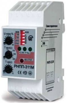
- Relay RNPP-311 Ukrainian production is one of the most popular and suitable for networks in the post-Soviet space. The abbreviation stands for voltage, skew and phase sequence relay. Modern modifications, in addition to the standard parameters, are also able to track the voltage frequency.
- OMRON K8AB this model controls not only the decrease, but also the excess of the voltage level, thereby performing the functions of a limiter or arrester, and much more efficiently. It has a number of modifications that differ in the adjustment of the response thresholds and technical parameters.
- Carlo Gavazzi DPC01 differs by two relays on the output terminals of the device. It has several adjustment points for various parameters, and a mode switch. Provides 7 possible functions for setting delays, intervals or cyclic functions.
- Relay EL-11 domestic production controls the parameters of the electrical network, can be used both in closed heated and unheated rooms. It is installed in any position, but requires protection from direct sunlight and atmospheric moisture.
Typical Wiring Diagrams
In most cases, the manufacturer sets all the necessary data on the method of connecting a particular relay to the case of each device. For example, let's take a few schemes from well-known manufacturers:
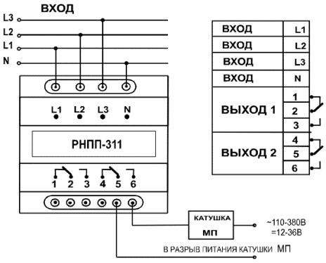
 Connection diagram RKF RNPP-311
 The diagram shows the connection of the terminal row to the corresponding phases of the line L1, L2, L3 and neutral N. At the output, it is possible to obtain two control circuits "Output 1" and "Output 2" that differ in voltage levels.

Power is supplied through the input channels L1, L2, L3 and through the neutral N. The output is two options - a three-phase three-wire system and a three-phase four-wire system, to work with the corresponding switch.

Unlike the previous options, the input terminals L1, L2, L3 are powered through fuses. The parameter adjustment block allows you to adjust the corresponding operating mode and the shutdown limits for them. Two manually switched outputs send control signals to switch devices.
The last two diagrams show the operation of the secondary load shedding circuits with the corresponding time delay on these terminals. As you can see, all connection schemes have identical components designed to monitor all network parameters that can signal a failure in the power supply of three-phase consumers.
 Consider each of the requirements for metal detectors
 Metal detector in an educational institution
 How to wipe the TV screen at home
 Senaki mikha tskhakaya. Mikha tskhakaya. Notable residents of the city
 International Journal of Applied and Basic Research Volgo-Caspian Shipping Canal Main Bank
 How to deal with sunburn if you are burned
 Hagen, Germany: why go, what to do, where to eat, travel tips Where and what to eat and drink in Hagen