Check for interturn short circuit of the pulse transformer winding. Simple tips on how to test a transformer with a multimeter for operability. Basics and working principle
The transformer is a simple electrical device and is used to convert voltage and current. The input and one or more output windings are wound on a common magnetic core. An alternating voltage applied to the primary winding induces a magnetic field, which causes an alternating voltage of the same frequency to appear in the secondary windings. The transmission coefficient changes depending on the ratio of the number of turns.
To check the faults of the transformer, first of all, it is necessary to determine the conclusions of all its windings. This can be done by it, where the pin numbers, type designation are indicated (then you can use the reference books), with a sufficiently large size there are even drawings. If the transformer is directly in some kind of electronic device, then the circuit diagram for the device and the specification will clarify all this.
Having determined all the conclusions, you can check two defects with a multimeter: an open winding and a short circuit to the case or another winding.
To determine the break, you need to "ring" in the ohmmeter mode in turn each winding, the absence of readings ("infinite" resistance) indicates a break.
The digital multimeter can give inaccurate readings when checking windings with a large number of turns due to their high inductance.
To search for a short to the case, one probe of the multimeter is connected to the winding terminal, and the second one alternately touches the terminals of the other windings (one of the two is enough) and the case (the contact point must be cleaned of paint and varnish). There should not be a short circuit, so it is necessary to check each output.
Turn-to-turn circuit of a transformer: how to determine
![]() Another common defect in transformers is turn-to-turn circuit, it is almost impossible to recognize it only with a multimeter. Mindfulness, keen eyesight and sense of smell can help. The wire is insulated only due to its varnish coating; in case of insulation breakdown between adjacent turns, the resistance still remains, which leads to local heating. During visual inspection on a serviceable transformer, there should be no blackening, streaks or swelling of the fill, charring of the paper, and the smell of burning.
Another common defect in transformers is turn-to-turn circuit, it is almost impossible to recognize it only with a multimeter. Mindfulness, keen eyesight and sense of smell can help. The wire is insulated only due to its varnish coating; in case of insulation breakdown between adjacent turns, the resistance still remains, which leads to local heating. During visual inspection on a serviceable transformer, there should be no blackening, streaks or swelling of the fill, charring of the paper, and the smell of burning.
If the type of transformer is determined, then according to the reference book you can find out the resistance of its windings. To do this, we use a multimeter in megger mode. After measuring the insulation resistance of the transformer windings, we compare it with the reference: differences of more than 50% indicate a winding malfunction. If the resistance of the transformer windings is not indicated, then the number of turns is always given, and the type of wire and theoretically, if desired, it can be calculated.
Can household step-down transformers be tested?
You can try to check with a multimeter the common classic step-down transformers used in power supplies for various devices with an input voltage of 220 volts and an output constant of 5 to 30 volts. Carefully, excluding the possibility of touching the bare wires, it is fed to the primary winding of 220 volts.
When smell, smoke, cod appear, you must turn off immediately, the experiment is unsuccessful, the primary winding is faulty.
If everything is normal, then touching only the tester probes, the voltage on the secondary windings is measured. The difference from the expected by more than 20% downwards indicates a malfunction of this winding.
Welding at home requires a functional and productive machine, which is now too expensive to purchase. It is quite possible to collect from scrap materials, having previously studied the corresponding scheme.
What are solar panels and how to create a home energy supply system with their help, will tell on this topic.
A multimeter can also help if there is a similar, but known good, transformer. The resistances of the windings are compared, a spread of less than 20% is the norm, but it must be remembered that for values less than 10 ohms, not every tester will be able to give correct readings.
The multimeter did the best it could. For further verification, you will need an oscilloscope.
Detailed instructions: how to check a transformer with a multimeter on video
N. Tyunin
Checking pulse transformers (IT) used in power supplies and line scan output stages (TDKS) of modern televisions using an ohmmeter (even digital) does not give positive results. The reason is that the IT windings, with the exception of the high-voltage TDKS windings, have a very low active resistance. The easiest (but not the most affordable) way is to measure the inductances of the windings and compare them with the passport data, if any. Another method, proposed in, is to check IT using a low-frequency generator operating at the resonant frequency of the circuit formed by the external capacitor C1 and the IT winding T1 (Fig. 1).
![]()
The proposed method for checking IT does not require a separate generator, but uses a calibrator available in almost every oscilloscope. As a rule, it is a generator of square-wave pulses with a frequency of 1 ... .2 kHz. The transformer under test is connected to the oscilloscope according to the diagram shown in Fig. 2. Oscillogram 1 (Fig. 3) corresponds to the shape of the output signal of the calibrator when it is not connected to IT, and oscillogram 2 - to the shape of the signal at the control point CT (see Fig. 2) after connecting the calibrator to the primary winding of T1. If the differentiated pulses are present at the control point and the amplitude of the Um2 signal approximately corresponds to the amplitude of the output signal of the calibrator Um1, then the tested IT can be considered serviceable. If there are no pulses, then we can make an unambiguous conclusion that one of the IT windings has a short circuit. A variant is possible when the signal has the form shown in oscillogram 3 (see Fig. 3) and its amplitude is greatly underestimated. This indicates that there are short-circuited turns in one of the IT windings.
![]()
The proposed verification method can be successfully applied without desoldering the IT from the circuit. In this case, one of the primary winding leads is disconnected from the circuit and connected to the calibrator output (see Fig. 2) and the IT is checked in the above sequence. The waveform on a working IT must correspond to oscillogram 2 (see Fig. 3). If one of the secondary rectifier diodes in the circuit is faulty or there are short-circuited turns in one of the IT windings, then the waveform will correspond to oscillogram 3.
Literature
A. Rodin, N. Tyunin. Repair of imported TVs. Repair, Issue 9. Moscow: Solon, 2000.
[email protected]
The main element of the power supply for digital devices is a current and voltage conversion device. Therefore, in the event of a breakdown of equipment, it is often the suspicion that falls on him. The easiest way to check the pulse transformer is with a multimeter. There are several measurement methods. Which one to choose depends on the situation and the expected damage. At the same time, it is not difficult to independently check any of them.
Converter design
Before proceeding directly to checking a pulse transformer (IT), it is advisable to know how it works, understand the principle of operation and distinguish between existing types. Such an impulse device is used not only as part of the power supply unit, it is used in the construction of short-circuit protection in idle mode and as a stabilizing element.
A pulse transformer is used to convert the magnitude of current and voltage without changing their shape. That is, it can change the amplitude and polarity of various kinds of impulses, coordinate various electronic cascades with each other, and create reliable and stable feedback. Therefore, the main requirement for it is the preservation of the pulse shape.
The magnetic circuit in the transformer is made of electrical steel plates, except for the toroidal shape, in which it is made of rolled or ferromagnetic material. Coil frames are placed on insulators, and only copper wires are used. The thickness of the plates is selected depending on the frequency.
The arrangement of the windings can be made in a spiral, conical and cylindrical form. A feature of the first type is the use of not wire, but a wide thin foil tape. Second, they are made with different insulation thicknesses, which affect the voltage between the primary and secondary windings. The third type is a structure with a wire wound on a rod in a spiral.
How the device works
![]() The principle of operation of IT is based on the occurrence of electromagnetic induction. So, if voltage is applied to the primary winding, then an alternating current will begin to flow through it. Its appearance will lead to the emergence of a magnetic flux that is not constant in magnitude. Thus, this coil is a kind of magnetic field source. This flux is transmitted through the short-circuited core to the secondary winding, inducing an electromotive force (EMF) on it.
The principle of operation of IT is based on the occurrence of electromagnetic induction. So, if voltage is applied to the primary winding, then an alternating current will begin to flow through it. Its appearance will lead to the emergence of a magnetic flux that is not constant in magnitude. Thus, this coil is a kind of magnetic field source. This flux is transmitted through the short-circuited core to the secondary winding, inducing an electromotive force (EMF) on it.
The value of the output voltage depends on the ratio of the number of turns between the primary winding and the secondary, and the maximum current strength depends on the cross-section of the wire used. When a powerful load is connected to the output, current consumption increases, which, with a small wire cross-section, leads the transformer to overheating, insulation damage and burnout.
The operation of IT also depends on the frequency of the signal that is fed to the primary winding. The higher this frequency is, the less losses will occur during energy transformation. Therefore, at a high speed of the supplied pulses, the dimensions of the device can be smaller. This is achieved by operating the magnetic circuit in saturation mode, and a small air gap is used to reduce the residual induction. This principle is used in the construction of an IT, to which a signal with a duration of only a few microseconds is applied.
Preparation and verification
 To test the performance of a pulse transformer, you can use both an analog multimeter and a digital one. The use of the second is preferable because of its ease of use. The essence of preparing a digital tester comes down to checking the battery and test leads. At the same time, the arrow-type device is additionally additionally adjusted.
The analog device is configured by switching the operating mode to the measurement area of the minimum possible resistance. After that, two wires are inserted into the tester's sockets and short-circuited. With a special trimming handle, the position of the arrow is set opposite to zero. If the arrow cannot be set to zero, then this indicates discharged batteries that will need to be replaced.
It's easier with a digital multimeter. Its design uses an analyzer that monitors the state of the battery and, if its parameters deteriorate, displays a message on the tester's screen about the need to replace it.
When checking the parameters of a transformer, two fundamentally different approaches are used. The first is to assess the health directly in the circuit, and the second is independent from it. But it is important to understand that if the IT is not removed from the circuit, or at least not disconnected a number of pins, then the measurement error can be very large. This is due to other radio elements that bypass the input and output of the device.
Defect detection procedure
![]() An important step in checking the transformer with a multimeter is to determine the windings. Moreover, their direction does not play a significant role. This can be done by the markings on the device. Usually a certain code is indicated on the transformer.
An important step in checking the transformer with a multimeter is to determine the windings. Moreover, their direction does not play a significant role. This can be done by the markings on the device. Usually a certain code is indicated on the transformer.
In some cases, a diagram of the location of the windings can be applied to the IT, or even their conclusions can be signed. If the transformer is installed in the device, then the circuit diagram or specification will help in finding the pinout. Also, often the designations of the windings, namely the voltage and the common terminal, are signed on the PCB itself near the connectors to which the device is connected.
After the conclusions are determined, you can proceed directly to checking the transformer. The list of malfunctions that may occur in the device is limited to four points:
- core damage;
- burnt-out contact;
- breakdown of insulation, leading to turn-to-turn or frame short circuit;
- wire break.
The sequence of testing is reduced to an initial external inspection of the transformer. It is carefully checked for blackening, chips, and odor. If no obvious damage is found, then proceed to measuring with a multimeter.
 To check the integrity of the windings, it is best to use a digital tester, but you can also examine them using a dial gauge. In the first case, the diode continuity mode is used, indicated on the multimeter by the symbol - |> | -))). To determine the break, test leads are connected to the digital device. One plugs into the connectors labeled V / Ω, and the other plugs into COM. The gallet switch is transferred to the continuity area. Measuring probes consistently touch each winding, red - to one of its terminals, and black - to the other. If it is intact, the multimeter will beep.
With an analog tester, the test is performed in the resistance measurement mode. For this, the smallest resistance measurement range is selected on the tester. This can be done via buttons or a switch. The probes of the device, as in the case of a digital multimeter, touch the beginning and end of the winding. If it is damaged, the arrow will remain in place and will not deviate.
The short circuit is checked in the same way. A short circuit may occur due to insulation breakdown. As a result, the resistance of the winding will decrease, which will lead to a redistribution of the magnetic flux in the device. The meter switches to resistance test mode for testing. Touching the probes to the windings, they watch the result on the digital display or on the scale (arrow deviation). This result should not be less than 10 ohms.
To make sure that there is no short circuit to the magnetic circuit, one probe touches the "gland" of the transformer, and the second - sequentially to each winding. There should be no deviation of the arrow or the appearance of a sound signal. It is worth noting that the tester can only ring the turn-to-turn circuit in an approximate form, since the error of the device is quite high.
Voltage and current measurements
If you suspect a transformer malfunction, testing can be carried out without disconnecting it completely from the circuit. This method of testing is called direct, but it carries the risk of getting an electric shock. The essence of actions in measuring current is to perform the following steps:
- one of the legs of the secondary winding is soldered from the circuit;
- the black wire is inserted into the COM jack of the multimeter, and the red wire is connected to the connector marked with the letter A;
- the device switch is moved to the position corresponding to the ACA zone.
- with a probe connected to the red wire, touch the free leg, and to the black one - the place to which it was soldered.
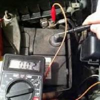
![]() When voltage is applied, if the transformer is operational, a current will begin to flow through it, the value of which can be seen on the tester screen. If the IT has several secondary windings, then the current strength is checked on each of them.
When voltage is applied, if the transformer is operational, a current will begin to flow through it, the value of which can be seen on the tester screen. If the IT has several secondary windings, then the current strength is checked on each of them.
The measurement of the voltage is as follows. The circuit with the transformer installed is connected to the power supply and then the tester switches to the ACV (alternating signal) area. Wire plugs plug into V / Ω and COM sockets and touch the beginning and end of the winding. If the IT is OK, the result will be displayed on the screen.
Removing characteristics
 To be able to check a transformer with a multimeter in this way, its current-voltage characteristic is required. This graph displays the relationship between the potential difference at the terminals of the secondary windings and the current that leads to their magnetization.
The essence of the method is as follows: the transformer is removed from the circuit, pulses of different magnitudes are fed to its secondary winding with the help of a generator. The power supplied to the coil must be sufficient to saturate the magnetic circuit. Each time the pulse changes, the current in the coil and the voltage at the output of the source are measured, and the magnetic circuit is demagnetized. To do this, after removing the voltage, the current in the winding increases in several approaches, after which it decreases to zero.
![]()
As the I - V characteristic is taken, its real characteristic is compared with the reference one. A decrease in its steepness indicates the appearance of an interturn short circuit in the transformer. It is important to note that to plot the current-voltage characteristic, it is necessary to use a multimeter with an electrodynamic head (pointer).
Thus, using an ordinary multimeter, it is possible with a high degree of probability to determine the operability of IT, but for this it is best to perform a set of measurements. Although for a correct interpretation of the result, one should understand the principle of operation of the device and imagine what processes occur in it, but in principle, for a successful measurement, it is enough just to be able to switch the device to different modes.
Frequency range "sweep":
LF power transformers: 40-60 Hz.
Switching power supply transformers: 8-40 kHz.
Isolation transformers, TDKS: 13-17 kHz.
Isolating transformers, TDKS monitors (for personal computers):
CGA: 13-17 kHz.
EGA: 13-25 kHz.
VGA: 25-50 kHz.
If you take a pulse power transformer, for example, a line scan isolation transformer, connect it according to Fig. 1, apply to the I winding U = 5 - 10V F = 10 - 100 kHz sinusoid through C = 0.1 - 1.0 μF, then on the II winding with the help of an oscilloscope we observe the shape of the output voltage.
Rice. 1. Connection diagram for method 1
Having "driven" the AF generator at frequencies from 10 kHz to 100 kHz, you need to get a pure sinusoid in some area (Fig. 2 on the left) without surges and "humps" (Fig. 2 in the center). The presence of diagrams in the entire range (Fig. 2. on the right) indicates interturn short circuits in the windings, etc. etc.
This technique, with a certain degree of probability, makes it possible to reject power transformers, various isolation transformers, and partly line transformers. It is only important to choose the frequency range.

Rice. 2. Forms of the observed signals
Method 2
Necessary equipment: LF generator, Oscilloscope.
Principle of operation:
The principle of operation is based on the phenomenon of resonance. An increase (from 2 times or more) in the amplitude of oscillations from the LF generator indicates that the frequency of the external generator corresponds to the frequency of the internal oscillations of the LC circuit.
To check, short-circuit winding II of the transformer. The oscillation in the LC circuit will disappear. It follows from this that short-circuited loops disrupt resonance phenomena in the LC circuit, which is what we sought.
The presence of short-circuited turns in the coil will also lead to the impossibility of observing resonance phenomena in the LC circuit.

Rice. 3. Connection diagram for method 2
We add that for testing the pulse transformers of power supplies, the capacitor C had a nominal value of 0.01 μF-1 μF, The generation frequency is selected empirically.
Method 3
Necessary equipment: LF generator, Oscilloscope.
Principle of operation:
The principle of operation is the same as in the second case, only a variant of a sequential oscillatory circuit is used.

Rice. 4. Connection diagram for method 3
The absence (breakdown) of oscillations (rather sharp) when the frequency of the LF generator changes indicates the resonance of the LC circuit. Everything else, as in the second method, does not lead to a sharp breakdown of oscillations on the control device (oscilloscope, AC millivoltmeter).
Transformers are widely used in electronics. They are ac voltage converters and, unlike other radioelements, rarely fail. To determine their serviceability, you need to know how to check a transformer with a multimeter. This method is quite simple, and it is necessary to understand the principle of operation of the transformer and its main characteristics.
Basic information about transformers
To convert AC voltage ratings, special electrical machines are used - transformers.
A transformer is an electromagnetic device designed to convert alternating voltage and current of one magnitude into alternating current and voltage of another magnitude.
Device and principle of operation
It is used in all power supply schemes for consumers, as well as for the transmission of electricity over long distances. The device of the transformer is quite primitive:
- The ferromagnetic core is made of a ferromagnet and is called a magnetic core. Ferromagnets are substances with spontaneous magnetization, parameters (atoms have constant spin or orbital magnetic moments) vary greatly due to the magnetic field and temperature.
- Windings: primary (mains voltage is connected) and secondary (power supply of a consumer or a group of consumers). There can be more than 2 secondary windings.
- Additional components are used for power transformers: coolers, gas relays, temperature indicators, moisture absorbers, current transformers, protection systems and continuous oil regeneration.
The principle of operation is based on finding a conductor in an alternating electric field. When a conductor moves, for example, a solenoid (a coil with a core), a voltage can be removed at its terminals, which depends in direct proportion to the number of turns. The transformer implements this approach, but it is not the conductor that moves, but the electric field formed by the alternating current. It moves along a magnetic circuit made of ferromagnet. Ferromagnet is a special alloy ideal for. Core materials:
- Electrical steel contains a large mass fraction of silicon (Si) and combines under the action of high temperature with carbon, the mass fraction of which is not more than 1%. Ferromagnetic properties are indistinct and eddy current losses (Foucault currents) occur. Losses increase in direct proportion with increasing frequency. To solve this problem, Si is added to carbon steel (E42, E43, E320, E330, E340, E350, E360). The abbreviation E42 stands for: E - electrical steel containing 4% - Si with 2% magnetic losses.
- Permalloy is a type of alloy, and its constituent parts are nickel and iron. This species is characterized by a high value of magnetic permeability. It is used in low-power transformers.
![]()
When current flows through the primary winding (I), a magnetic flux Ф is formed in its turns, which spreads along the magnetic circuit to the II winding, as a result of which an EMF (electromotive force) is formed in it. The device can operate in 2 modes: load and idle.
Transformation ratio and its calculation
![]() The transformation ratio (k) is a very important characteristic. Thanks to him, you can identify malfunctions. The transformation ratio is a value that shows the ratio of the number of turns of the I winding to the number of turns of the II winding. For k transformers are:
The transformation ratio (k) is a very important characteristic. Thanks to him, you can identify malfunctions. The transformation ratio is a value that shows the ratio of the number of turns of the I winding to the number of turns of the II winding. For k transformers are:
- Decreasing (k> 1).
- Increasing (k< 1).
It is easy to find it, and for this it is necessary to know the voltage ratio of each of the windings. If there are more than 2 windings, the calculation is made for each of them. To accurately determine k, you need to use 2 voltmeters, since the mains voltage can change, and these changes need to be monitored. Only the voltage specified in the specifications needs to be applied. K is defined in several ways:
According to the passport, which indicates all the parameters of the device (supply voltage, transformation ratio, wire cross-section on the windings, number of turns, type of magnetic circuit, dimensions).
- Calculation method.
- With the help of the Schering bridge.
- Using special equipment (for example, UIKT-3).
Calculating k is easy, and there are a number of formulas that can be used to do this. There is no need to take into account the losses of the magnetic circuit used during manufacture at the factory. Studies have shown the relationship between the magnetic circuit (iron ore) and k. To improve the efficiency of the transformer, you need reduce magnetic losses:
- The use of special alloys for the magnetic circuit (thickness reduction and special processing).
- Reducing the number of turns when using a thick wire, and at high frequencies, a large cross section provides room for eddy currents.
For these purposes, amorphous steel is used. But it also has a limitation called magnetostriction (change in the geometric dimensions of the material under the influence of an electromagnetic field). When using this technology, it is possible to obtain sheets for iron ore with a thickness of hundredths of a millimeter.
Calculation formulas
In the absence of appropriate documentation, you need to make calculations yourself. In each case, the calculation methods are different. Basic formulas for calculating k:
- Without taking into account possible errors: k = U1 / U2 = n1 / n2, where U1 and U2 are U on I and II windings, n1 and n2 are the number of turns on I and II windings.
- Taking into account the errors: k = U1 / U2 = (e * n1 + I1 * R1) / (e * n2 + I2 * R2), where U1 and U2 are voltages on I and II windings; n1 and n2 - number of turns on I and II windings; e - EMF (electromotive force) in each of the turns of the windings; I1 and I2 - current strengths of I and II windings; R1 and R2 are resistances for I and II.
- According to the known powers when the windings are connected in parallel: kz = Z1 / Z2 = ku * ku, where kz is k in terms of power, Z1 and Z2 are the powers on the primary and secondary windings, ku is k in terms of voltage (k = U1 / U2).
- By currents with serial connection of windings: k = I1 / I2 = n2 / n1. Taking into account the resulting no-load current (loss current Io): I1 * n1 = I2 * n2 + Io.
Serviceability check
Mostly transformers are used in power supplies. Winding and manufacturing the transformer itself from scratch is a difficult task and not everyone can do it. Therefore, a ready-made one is taken as a basis and is modernized by changing the number of turns of the secondary winding. The main faults of the transformer:
- Break of conclusions.
- Damage to the magnetic circuit.
- Violation of isolation.
- Combustion at short circuit.
Diagnosis begins with a visual inspection. Initial diagnostics includes an inspection of the transformer terminals, its coils for charring, the integrity of the magnetic circuit.
![]()
If the leads are worn out, it is necessary to clean them, and in some cases, in the event of a break, disassemble the transformer, solder them and ring with a tester.
If the magnetic circuit is damaged, you need to replace it or find out from the reference books about the same for a particular model, since it cannot be repaired. Individual plates can be replaced.
In case of short circuit, it is necessary to carry out diagnostics for operability using measuring instruments (checking the transformer with a multimeter).
When the insulation is broken, contact occurs between the turns of the windings or to the case. It is quite difficult to determine this malfunction. For this it is necessary to perform the following actions:
- Switch the device on to resistance measurement mode.
- One probe must be on the case, and the other must be connected to each terminal of the transformer in turn.
- In all cases, the device should show infinity, which indicates the absence of a short circuit to the case.
- With any readings of the device, a breakdown to the case exists, and it is necessary to completely disassemble the transformer and even unwind its windings to find out the reason.
To search for short-circuited turns, you need to determine where I is the winding (input), and where II (output) for an unknown transformer. For this it is worth using the following algorithm:
- Find out the resistance of the primary winding of the 220 volt transformer by measuring the multimeter in the "resistance" mode. It is necessary to record the readings of the device. Select the winding with the highest resistance.
- Take a 50 W bulb and connect it in series with this winding.
- Plug in for 5-7 seconds.
After that, turn off and check the windings for heating. If there is no noticeable temperature rise, then proceed to the search for short-circuited loops. How to check a transformer for turn-to-turn circuit: you need to use a megohmmeter at a voltage of 1000 V. When measuring insulation breakdown, it is necessary to ring the case and the terminals of the windings, as well as independent windings, for example, terminal I and II.
It is necessary to determine the transformation ratio and compare it with the document. If they match, the transformer is operational.
![]() There are two more verification methods:
There are two more verification methods:
- Direct - implies testing under load. For its implementation, it is necessary to assemble the power supply circuit of the I and II windings. By measuring the values of the current in the windings, and then using the formulas (4), determine k and compare it with the passport data.
- Indirect methods. Includes: checking the polarity of the winding leads, determining the characteristics of magnetization (rarely used). The polarity is determined using a voltmeter or ammeter of magnetoelectric design with the determination of the polarity at the output. When the arrow is deflected to the right, the polarities coincide.
Checking a pulse transformer is quite complicated and can only be done by an experienced radio amateur. There are many ways to check the health of impulses.
Thus, the transformer can be easily checked with a multimeter, knowing the main features and the checking algorithm. To do this, you need to find out the type of transformer, find documentation for it and calculate the transformation ratio. In addition, it is necessary to carry out a visual inspection of the device.
 Simple tips on how to test a transformer with a multimeter for operability
 Repair of uninterruptible power supplies Commercial proposal for the repair of an uninterruptible power supply
 Do-it-yourself UPS repair: wizard's advice Repair of apc uninterruptible power supplies
 Repair of a multimeter m 830b does not show an ohmmeter
 Programs for drawing electrical circuits
 Drawing boards in Sprint-Layout correctly from the first steps
 What program can open the file