Design and repair of uninterruptible power supplies from ars. Repair of uninterruptible power supplies Commercial proposal for the repair of an uninterruptible power supply
An uninterruptible power supply is a device that allows computers and other electrical equipment to work for some time in the event of a power outage. It also allows you to control the frequency of the voltage supplied to the equipment to ensure optimal operation. A UPS is essential for the smooth operation of your equipment. since power outages and power surges are not uncommon. Like any other equipment, UPSs tend to break down, this is a natural and inevitable process, therefore, the repair of uninterruptible power supplies is a problem that almost all owners of computer equipment have to face.
 Typical UPS faults:
- UPS does not turn on
- UPS gives an error message
- UPS does not charge the battery
- UPS does not switch to mains mode
- UPS beeps continuously
- UPS does not provide the expected backup time
- UPS does not give out output voltage
In any case, no matter what breakdown occurs, you should not do the UPS repair yourself. This work should be entrusted to qualified specialists, because diagnostics and repair of UPS at home is almost impossible due to the need for special equipment. The AF-Service Technical Center repairs any type of UPS. Also, you can order diagnostics of your UPS from us, which can help you in making a decision on repair. It is also worth noting that timely UPS prevention can prevent the failure of expensive machine components and save your budget..
|
Estimated price for UPS repair services |
|
| Diagnostics in case of refusal to repair | RUB 500.00 |
| UPS Prevention | from 1200,00 rub. |
| Calibration | from 500,00 rub. |
| Battery replacement (for 1 unit) | from 400,00 rub. |
| Repair of the electronics of the power / control board | from 1500,00 rub. |
| Minor repairs of plastic parts / load-bearing elements | from 500,00 rub. |
| Medium repair of plastic parts / load-bearing elements | from 1100,00 rub. |
| Complex repair of plastic parts / load-bearing elements | from 1600,00 rub. |
Order UPS repair through the website with a 10% discount!
The complete lack of information about such common devices as uninterruptible power supplies is surprising. We are breaking through the information blockade and are starting to publish materials on their construction and repair. From the article you will get a general idea of the existing types of uninterruptible power supplies and a more detailed, at the level of a schematic diagram, about the most common Smart-UPS models.
The reliability of computers is largely determined by the quality of the electrical network. Power interruptions, such as surges, surges, sags, and power outages, can result in keyboard locks, data loss, system board damage, and more. Uninterruptible power supplies (UPS) are used to protect high-value computers from mains-related troubles. The UPS eliminates problems associated with poor quality power or temporary lack of power, but is not a long-term alternative power source like a generator.
According to the expert-analytical center "SK PRESS", in 2000 the volume of UPS sales in the Russian market amounted to 582 thousand units. If we compare these estimates with data on sales of computers (1.78 million pieces), it turns out that in 2000, every third computer purchased is equipped with an individual UPS.
The overwhelming part of the Russian UPS market is occupied by products of six companies: APC, Chloride, Invensys, IMV, Liebert, Powercom. APC products have been maintaining the leading position in the Russian UPS market for many years.
UPSs are divided into three main classes: Off-line (or stand-by), Line-interactive and On-line. These devices have various designs and characteristics.
Rice. 1. Block diagram of an off-line UPS
A block diagram of an Off-line UPS is shown in Fig. 1. During normal operation, the load is supplied by the filtered mains voltage. EMI / RFI Noise filters on metal oxide varistors are used to suppress EMI and RFI in the input circuits. If the input voltage falls below or above the set value, or disappears altogether, the inverter turns on, which is normally off. By converting the DC voltage of the batteries into AC, the inverter supplies the load from the batteries. The shape of its output voltage is rectangular pulses of positive and negative polarity with an amplitude of 300 V and a frequency of 50 Hz. Off-line UPSs operate uneconomically in power grids with frequent and significant voltage deviations from the nominal value, since frequent switching to operation on battery power reduces the service life of the latter. The power of the Back-UPS Off-line UPS models manufactured by APC is in the range of 250 ... 1250 VA, and the Back-UPS Pro models are in the range of 2S0 ... 1400 VA.

Rice. 2. Block diagram of a Line-interactive UPS
A block diagram of a Line-interactive UPS is shown in Fig. 2. Just like the Off-line UPS, they relay the AC mains voltage to the load, while absorbing relatively small voltage surges and smoothing out noise. The input circuits use an EMI / RFI Noise filter on metal oxide varistors to suppress EMI and RFI. If an emergency occurs in the mains, then the UPS synchronously, without losing the phase of the oscillation, turns on the inverter to supply the load from the batteries, while the sinusoidal shape of the output voltage is achieved by filtering the PWM oscillation. The circuit uses a special inverter to recharge the battery, which also works during line voltage surges. The range of operation without battery connection is expanded due to the use of an autotransformer with a switched winding in the input circuits of the UPS. Transition to battery power occurs when utility voltage is out of range. The power of the Line-interactive class Smart-UPS UPS manufactured by ARS is 250 ... 5000 VA.
Rice. 3. Block diagram of the UPS class On-line
The block diagram of the UPS of the On-line class is shown in Fig. 3. These UPSs convert the AC input voltage to DC, which is then converted back to stable AC by means of a PWM inverter. Since the load is always supplied by the inverter, there is no need to switch from the mains to the inverter, and the transfer time is zero. Due to the inertial DC link, which is the battery, the load is isolated from mains anomalies and a very stable output voltage is formed. Even with large deviations in the input voltage, the UPS continues to supply the load with pure sinusoidal voltage with a deviation of no more than + 5% of the user-set nominal value. APC On-line UPSs have the following output powers: Matrix UPS models - 3000 and 5000 VA, Symmetra Power Array models - 8000, 12000 and 16000 VA.
The Back-UPS models do not use a microprocessor, while the Back-UPS Pro, Smart-UPS, Smart / VS, Matrix, and Symmetna use a microprocessor.
The most widely used devices are: Back-UPS, Back-UPS pro, Smart-UPS, Smart-UPS / VS.
Devices such as Matrix and Symmetna are used primarily for banking systems.
In this article, we will consider the design and diagram of the Smart-UPS 450VA ... 700VA models used to power personal computers (PCs) and servers. Their technical characteristics are given in table. one.
Table 1. Specifications for APC Smart-UPS models
| Model | 450VA | 620VA | 700VA | 1400VA |
|---|---|---|---|---|
| Allowable input voltage, V | 0...320 | |||
| Input voltage for mains operation *, V | 165...283 | |||
| Output voltage *, V | 208...253 | |||
| Input circuit overload protection | Resettable circuit breaker | |||
| Frequency range for mains operation, Hz | 47...63 | |||
| Time of switching to battery power, ms | 4 | |||
| Maximum load power, VA (W) | 450(280) | 620(390) | 700(450) | 1400(950) |
| Output voltage during battery operation, V | 230 | |||
| Frequency when operating on battery, Hz | 50 ± 0.1 | |||
| Signal waveform when operating on battery power | Sinusoid | |||
| Output circuit overload protection | Overload and short-circuit protection, overload latching shutdown | |||
| Battery Type | Lead sealed, maintenance-free | |||
| Number of batteries x voltage, V, | 2 x 12 | 2 x 6 | 2 x 12 | 2 x 12 |
| Battery capacity, Ah | 4,5 | 10 | 7 | 17 |
| Battery life, years | 3...5 | |||
| Full charge time, h | 2...5 | |||
| UPS dimensions (height x width x length), cm | 16.8x11.9x36.8 | 15,8x13,7x35,8 | 21.6x17x43.9 | |
| Net weight (gross), kg | 7,30(9,12) | 10,53(12,34) | 13,1(14,5) | 24,1(26,1) |
* User adjustable using PowerChute software.
UPS Smart-UPS 450VA ... 700VA and Smart-UPS 1000VA ... 1400VA have the same electrical circuit and differ in battery capacity, the number of output transistors in the inverter, the power of the power transformer and dimensions.
Consider the parameters that characterize the quality of electricity, as well as terminology and designations.
Power problems can be expressed as:
In Russia, voltage dips, power outages and surges both up and down account for approximately 95% of deviations from the norm, the rest is noise, impulse noise (needles), high-frequency surges.
Volt-Amperes (VA, VA) and Watts (W, W) are used as power units. They differ in power factor PF (Power Factor):
The power factor for computer technology is 0.6 ... 0.7. The number in the designation of APC UPS models indicates the maximum power in VA. For example, the Smart-UPS 600VA model has a power of 400W, and the 900VA model has 630W.
The block diagram of the Smart-UPS and Smart-UPS / VS models is shown in Fig. 4. Mains voltage is applied to the EM / RFI input filter to suppress mains noise. At rated mains voltage, relays RY5, RY4, RY3 (pins 1, 3), RY2 (pins 1, 3), RY1 are switched on, and the input voltage is passed to the load. Relays RY3 and RY2 are used for the BOOST / TRIM output voltage trim mode. For example, if the mains voltage increased and went beyond the permissible limit, relays RY3 and RY2 connect an additional winding W1 in series with the main W2. An autotransformer with a transformation ratio is formed
K = W2 / (W2 + W1)
less than one and the output voltage drops. In the event of a decrease in the mains voltage, the additional winding W1 is reversed by the relay contacts RY3 and RY2. Transformation ratio
K = W2 / (W2 - W1)
becomes greater than one, and the output voltage rises. The adjustment range is ± 12%, the hysteresis value is selected by the Power Chute software.
In the event of a voltage loss at the input, the RY2 ... RY5 relays are turned off, a powerful PWM inverter powered by a battery turns on, and a sinusoidal voltage of 230 V, 50 Hz is supplied to the load.
The multi-tier power grid noise suppression filter consists of varistors MV1, MV3, MV4, choke L1, capacitors C14 ... C16 (Fig. 5). The CT1 transformer analyzes the high-frequency components of the mains voltage. The CT2 transformer is a load current sensor. The signals from these sensors, as well as the RTH1 temperature sensor, are fed to the analog-to-digital converter IC10 (ADC0838) (Fig. 6).
Transformer T1 is an input voltage sensor. The command to turn on the device (AC-OK) is sent from the two-level comparator IC7 to the base of Q6. Transformer T2 - output voltage sensor for Smart TRIM / BOOST mode. From pins 23 and 24 of IC1 2 (Fig. 6), the BOOST and TRIM signals are fed to the bases of transistors Q43 and Q49 to switch relays RY3 and RY2, respectively.
The phase synchronization signal (PHAS-REF) from pin 5 of transformer T1 goes to the base of transistor Q41 and from its collector to pin 14 of IC12 (Figure 6).
The Smart-UPS model uses an IC12 microprocessor (S87C654), which:
The EEPROM IC13 stores the factory settings, as well as the calibrated settings for the signal levels of frequency, output voltage, transition limits, battery charging voltage.
Digital-to-analog converter IC15 (DAC-08CN) generates a sinusoidal reference signal at pin 2, which is used as a reference for IC17 (APC2010).
The PWM signal is generated by IC14 (APC2020) in conjunction with IC17. Powerful field-effect transistors Q9 ... Q14, Q19 ... Q24 form a bridge inverter. During the positive half-wave of the PWM signal, Q12 ... Q14 and Q22 ... Q24 are open, and Q19 ... Q21 and Q9 ... Q11 are closed. During the negative half-wave, Q19 ... Q21 and Q9 ... Q11 are open, and Q12 ... Q14 and Q22 ... Q24 are closed. Transistors Q27 ... Q30, Q32, Q33, Q35, Q36 form push-pull drivers that generate control signals for powerful field-effect transistors with a large input capacitance. The load of the inverter is the transformer winding, it is connected by wires W5 (yellow) and W6 (black). A sinusoidal voltage of 230 V, 50 Hz is generated on the secondary winding of the transformer to power the connected equipment.
Inverter reverse operation is used to charge the battery with a ripple current during normal UPS operation.
The UPS has a built-in SNMP slot that allows you to connect additional cards to expand the UPS's capabilities:
The UPS has several voltages required for the normal operation of the device: 24 V, 12 V, 5 V and -8 V. To check them, you can use table. 2. Measure the resistance from the terminals of the microcircuits to the common wire with the UPS turned off and the discharged capacitor C22. Typical faults of UPS Smart-Ups 450VA ... 700VA and how to eliminate them are shown in Table. 3.
Table 3. Typical UPS faults Smart-Ups 450VA ... 700VA
| Brief description of the defect | Possible reason | Troubleshooting method |
|---|---|---|
| UPS does not turn on | Batteries not connected | Connect batteries |
| Bad or defective battery, low capacity | Replace battery. The capacity of the charged battery can be checked with the high beam lamp from the car (12V, 150W) | |
| Powerful field-effect transistors of the inverter are pierced | In this case, there is no voltage at the terminals of the battery connected to the UPS board. Check with an ohmmeter and replace transistors. Check the resistors in their gate circuits. Replace IC16 | |
| Broken flexible cable connecting the display | This fault can be caused by shorting the flex cable leads in the UPS chassis. Replace the flex cable that connects the display to the main board of the UPS. Check if fuse F3 and transistor Q5 are working | |
| The power button is pressed | Replace SW2 button | |
| UPS turns on on battery power only | Fuse F3 blown | Replace F3. Check the health of transistors Q5 and Q6 |
| UPS will not start. Battery replacement indicator is on | If the battery is good, the UPS is not running the program correctly. | Calibrate the battery voltage using the proprietary program from APC |
| UPS does not come on line | Mains cable cut or connection broken | Connect the network cable. Check the condition of the automatic plug with an ohmmeter. Check the hot-neutral cord connection. |
| Cold soldering of board elements | Check the health and quality of the rations of elements L1, L2 and especially T1 | |
| Defective varistors | Check or replace varistors MV1 ... MV4 | |
| Load shedding occurs when the UPS is turned on | Defective voltage sensor T1 | Replace T1. Check the health of the elements: D18 ... D20, C63 and C10 |
| Display indicators are flashing | The capacity of the capacitor C17 has decreased | Replace capacitor C17 |
| Capacitor leakage is likely | Replace C44 or C52 | |
| Defective relay contacts or board elements | Replace relay. Replace IC3 and D20. It is better to replace the diode D20 with 1N4937 | |
| UPS overload | The connected equipment exceeds the rated power | Reduce load |
| Defective transformer T2 | Replace T2 | |
| Defective current sensor CT1 | Replace CT1. A resistance greater than 4 ohms indicates a faulty current sensor | |
| Defective IC15 | Replace IC15. Check the voltage -8 V and 5 V. Check and replace if necessary: IC12, IC8, IC17, IC14 and the power field-effect transistors of the inverter. Check power transformer windings | |
| Battery does not charge | UPS program does not work properly | Calibrate the battery voltage with a proprietary program from the APC. Check constants 4, 5, 6, 0. Constant 0 is critical for every UPS model. Check the constant after replacing the battery |
| The battery charging circuit is out of order | Replace IC14. Check the 8 V voltage at the pin. 9 IC14, if not, replace C88 or IC17 | |
| Battery defective | Replace battery. Its capacity can be checked with a high beam lamp from a car (12V, 150W) | |
| Microprocessor IC12 defective | Replace IC12 | |
| UPS does not start up when turned on, a click is heard | Defective reset circuit | Check serviceability and replace faulty elements: IC11, IC15, Q51 ... Q53, R115, C77 |
| Indicator defect | The indication circuit is faulty | Check and replace faulty Q57 ... Q60 on the indicator board |
| UPS does not work in On-line mode | Defective board elements | Replace Q56. Check the health of the elements: Q55, Q54, IC12. IC13 is defective or will have to be reprogrammed. The program can be taken from a working UPS |
| When transferring to battery operation, the UPS shuts down and turns on spontaneously | Broken transistor Q3 | Replace transistor Q3 |
In the second part of the article, the UPS device of the On-line class will be considered,
OFF-LINE UPS UNIT
APC Off-line UPS includes Back-UPS models. UPSs of this class are distinguished by their low cost and are designed to protect personal computers, workstations, network equipment, trade and point-of-sale terminals. Power of manufactured Back-UPS models is from 250 to 1250 VA. The main technical data of the most common UPS models are presented in table. 3.
Table 3. Main technical data of UPS class Back-UPS
| Model | BK250I | BK400I | BK600I |
|---|---|---|---|
| Rated input voltage, V | 220...240 | ||
| Rated mains frequency, Hz | 50 | ||
| Energy of absorbed emissions, J | 320 | ||
| Peak emission current, A | 6500 | ||
| IEEE 587 Cat. A 6kVA,% | <1 | ||
| Switching voltage, V | 166...196 | ||
| Output voltage when operating from batteries, V | 225 ± 5% | ||
| Output frequency when operating on batteries, Hz | 50 ± 3% | ||
| Maximum power, VA (W) | 250(170) | 400(250) | 600(400) |
| Power factor | 0,5. ..1,0 | ||
| Crest factor | <5 | ||
| Nominal switching time, ms | 5 | ||
| Number of batteries x voltage, V | 2x6 | 1x12 | 2x6 |
| Battery capacity, Ah | 4 | 7 | 10 |
| Time of 90% recharging after discharging to 50%, hour | 6 | 7 | 10 |
| Acoustic noise at a distance of 91 cm from the device, dB | <40 | ||
| UPS operating time at full capacity, min | >5 | ||
| Maximum dimensions (H x W x D), mm | 168x119x361 | ||
| Weight, kg | 5,4 | 9,5 | 11,3 |
The index "I" (International) in the names of UPS models means that the models are designed for an input voltage of 230 V, the devices are equipped with sealed lead-acid maintenance-free batteries with a service life of 3 ... 5 years according to the Euro Bat standard. All models are equipped with suppressor filters that suppress surges and high-frequency noise in the mains voltage. The devices give appropriate audible signals when the input voltage is lost, the batteries are discharged and overloaded. The mains voltage threshold below which the UPS switches to battery operation is set using the switches on the back of the unit. Models BK400I and BK600I have an interface port connected to a computer or server for automatic self-closing of the system, a test switch and an audible signal switch.
The block diagram of the UPS Back-UPS 250I, 400I and 600I is shown in Fig. 8. Mains voltage is supplied to the input multistage filter through a circuit breaker. The circuit breaker is designed as a circuit breaker on the back of the UPS. In the event of a significant overload, it disconnects the device from the network, while the contact column of the switch is pushed up. To turn on the UPS after an overload, it is necessary to reset the contact bar of the breaker. The input EMI and RFI filter uses LC links and metal oxide varistors. During normal operation, pins 3 and 5 of RY1 are closed and the UPS transfers utility power to the load, filtering out high frequency interference. The charging current flows continuously as long as there is voltage in the network. If the input voltage drops below the set value or disappears altogether, or if it is very noisy, contacts 3 and 4 of the relay close, and the UPS switches to operation from the inverter, which converts the DC voltage of the batteries into AC. The switching time is about 5 ms, which is quite acceptable for modern switching power supplies for computers. The waveform at the load is rectangular pulses of positive and negative polarity with a frequency of 50 Hz, a duration of 5 ms, an amplitude of 300 V, an effective voltage of 225 V. At idle, the pulse duration is reduced, and the effective output voltage drops to 208 V. Unlike Smart models -UPS, the Back-UPS does not have a microprocessor, comparators and logic chips are used to control the device.
A schematic diagram of the Back-UPS 250I, 400I and 600I is almost completely shown in Fig. 9 ... 11. The multi-tier power supply noise suppression filter consists of varistors MOV2, MOV5, chokes L1 and L2, capacitors C38 and C40 (Fig. 9). Transformer T1 (Fig. 10) is an input voltage sensor. Its output voltage is used for battery charging (this circuit uses D4 ... D8, IC1, R9 ... R11, C3 and VR1) and analysis of the mains voltage.
If it disappears, then the circuit on the elements IC2 ... IC4 and IC7 connects a powerful inverter powered by a battery. The ACFAIL command to turn on the inverter is generated by IC3 and IC4. The circuit, consisting of comparator IC4 (pins 6, 7, 1) and electronic key IC6 (pins 10, 11, 12), enables the operation of the inverter with a log signal. "1" on pins 1 and 13 of IC2.
The divider consisting of resistors R55, R122, R1 23 and switch SW1 (pins 2, 7 and 3, 6) located on the rear side of the UPS determines the mains voltage below which the UPS switches to battery power. The factory setting for this voltage is 196 V. In areas with frequent fluctuations in the mains voltage resulting in frequent UPS switches to battery power, the threshold voltage should be set to a lower level. The fine adjustment of the threshold voltage is performed by the VR2 resistor.
During battery operation, IC7 generates inverter excitation pulses PUSHPL1 and PUSHPL2. In one arm of the inverter, powerful field-effect transistors Q4 ... Q6 and Q36 are installed, in the other -Q1 ... Q3 and Q37. The transistors are loaded by their collectors on the output transformer. The secondary winding of the output transformer generates an impulse voltage with an effective value of 225 V and a frequency of 50 Hz, which is used to power the equipment connected to the UPS. The duration of the pulses is regulated by the variable resistor VR3, and the frequency - by the resistor VR4 (Fig. 10). Turning on and off the inverter is synchronized with the mains voltage by the circuit on the elements IC3 (pins 3 ... 6), IC6 (pins 3 ... 5, 6, 8, 9) and IC5 (pins 1 ... 3 and 11 ... 13). Circuit on the elements SW1 (pins 1 and 8), IC5 (pins 4 ... B and 8 ... 10), IC2 (pins 8 ... 10), IC3 (pins 1 and 2), IC10 (pins 12 and 13), D30, D31, D18, Q9, BZ1 (fig. 11) activates the buzzer to warn the user of power supply problems. During battery operation, the UPS emits a single beep every 5 seconds to indicate the need to save user files. battery capacity is limited. When operating on battery power, the UPS monitors battery capacity and emits a continuous beep before battery discharge. If pins 4 and 5 of switch SW1 are open, then this time is 2 minutes, if closed - 5 minutes. To turn off the sound signal, you must close the terminals 1 and 8 of the SW1 switch.
All Back-UPS models, with the exception of the BK250I, have a bi-directional communication port for communication with a PC. Power Chute Plus software allows the computer to both monitor the UPS and safely shutdown the operating system (Novell, Netware, Windows NT, IBM OS / 2, Lan Server, Scounix and UnixWare, Windows 95/98) while saving the user's files. In fig. 11 this port is designated J14. Purpose of its conclusions: 1 - UPS SHUTDOWN. The UPS shuts down if a log appears on this pin. "1" for 0.5 s.
2 - AC FAIL. When switching to battery power, the UPS generates a log on this pin. "one".
3 - CC AC FAIL. When switching to battery power, the UPS generates a log on this output. "0". Open collector output.
4, 9 - DB-9 GROUND. Common wire for signal input / output. The terminal has a resistance of 20 ohms with respect to the common wire of the UPS.
5 - CC LOW BATTERY. In case of battery discharge, the UPS generates a log on this output. "0". Open collector output.
6 - OS AC FAIL When switching to battery power, the UPS generates a log on this output. "one". Open collector output.
7, 8 - not connected.
Open collector outputs can be connected to TTL circuits. Their load capacity is up to 50 mA, 40 V. If you need to connect a relay to them, then the winding should be shunted with a diode.
A regular "null modem" cable is not suitable for this port, the corresponding RS-232 interface cable with a 9-pin connector is supplied with the software.
UPS CALIBRATION AND REPAIR
Setting the frequency of the output voltage
To set the frequency of the output voltage, connect an oscilloscope or frequency meter to the UPS output. Turn the UPS into battery mode. When measuring the frequency at the UPS output, adjust the VR4 resistor to 50 ± 0.6 Hz.
Setting the output voltage value
Turn the UPS into battery mode without load. Connect a voltmeter to the UPS output to measure the effective voltage value. By adjusting the VR3 resistor, set the voltage at the UPS output to 208 ± 2 V.
Setting the threshold voltage
Set switches 2 and 3 on the rear of the UPS to OFF. Connect the UPS to a LATR-type transformer with continuously variable output voltage. Set the voltage of 196 V at the LATR output. Turn the VR2 resistor counterclockwise until it stops, then slowly turn the VR2 resistor clockwise until the UPS switches to battery power.
Setting the charging voltage
Set the UPS input to 230 V. Disconnect the red wire to the positive battery terminal. Using a digital voltmeter, adjust the VR1 resistor to set the voltage on this wire to 13.76 ± 0.2 V relative to the common point of the circuit, then restore the connection to the battery.
Typical malfunctions
Typical malfunctions and methods for their elimination are given in table. 4, and in table. 5 - analogs of the most frequently failing components.
Table 4. Typical Back-UPS 250I, 400I and 600I Faults
| Defect manifestation | Possible reason | Defect finding and elimination method |
|---|---|---|
| Smoke smell, UPS is not working | Input filter defective | Check the health of the MOV2, MOV5, L1, L2, C38, C40 components, as well as the board conductors connecting them |
| UPS will not turn on. Indicator is off | UPS input circuit breaker (circuit breaker) disabled | Reduce the load on the UPS by disconnecting some of the equipment, and then turn on the circuit breaker by pressing the contact column of the circuit breaker |
| Defective accumulator batteries | Replace batteries | |
| Batteries not connected correctly | Check if the batteries are connected correctly | |
| Inverter defective | Check that the inverter is working properly. To do this, disconnect the UPS from the AC mains, disconnect the batteries and discharge the C3 capacity with a 100 Ohm resistor, ring the drain-source channels of the powerful field-effect transistors Q1 ... Q6, Q37, Q36 with an ohmmeter. If the resistance is a few ohms or less, replace the transistors. Check the resistors in the gates R1 ... R3, R6 ... R8, R147, R148. Check the health of transistors Q30, Q31 and diodes D36 ... D38 and D41. Check fuses F1 and F2 | |
| Replace IC2 | ||
| When turned on, the UPS disconnects the load | Defective transformer T1 | Check the health of the windings of the transformer T1. Check the tracks on the board connecting the T1 windings. Check fuse F3 |
| The UPS is operating on battery power even though mains voltage is present | The mains voltage is very low or distorted | Check the input voltage with an indicator or meter. If it is permissible for the load, reduce the sensitivity of the UPS, i.e. change the response limit using switches located on the back of the device |
| UPS turns on, but no voltage is supplied to the load | Defective relay RY1 | Check the health of relay RY1 and transistor Q10 (BUZ71). Check the health of IC4 and IC3 and the supply voltage at their terminals |
| Check the tracks on the board connecting the relay contacts | ||
| The UPS hums and / or shuts down the load, not providing the expected backup time | Defective inverter or one of its elements | See sub-item "Inverter defective" |
| UPS does not provide expected backup time | Batteries are flat or lost capacity | Charge the batteries. They need to be recharged after extended power outages. In addition, batteries age quickly with frequent use or under high temperature conditions. If the batteries are approaching the end of their service life, it is advisable to replace them, even if the battery replacement alarm has not yet been sounded. Check the capacity of the charged battery with a vehicle high beam 12 V, 150 W |
| UPS overloaded | Reduce the number of consumers at the UPS output | |
| UPS does not turn on after battery replacement | Incorrect connection of batteries when replacing them | Check if the batteries are connected correctly |
| The UPS emits a loud tone when turning on, sometimes with a decreasing tone | Defective or discharged rechargeable batteries | Charge the batteries for at least four hours. If the problem persists after recharging, the batteries should be replaced. |
| Batteries do not charge | Diode D8 is faulty | Check if D8 is working properly. Its reverse current should not exceed 10 μA |
| Charge voltage below required level | Calibrate Battery Charge Voltage |
Table 5. Analogs for replacing defective components
| Schematic designation | Defective component | Possible replacement |
|---|---|---|
| IC1 | LM317T | LM117H, LM117K |
| IC2 | CD4001 | K561LE5 |
| IC3, IC10 | 74S14 | Consists of two K561TL1 microcircuits, the outputs of which are connected according to the pinout on the microcircuit |
| IC4 | LM339 | K1401SA1 |
| IC5 | CD4011 | K561LA7 |
| IC6 | CD4066 | K561KT3 |
| D4 ... D8, D47, D25 ... D28 | 1N4005 | 1N4006, 1N4007, BY126, BY127, BY133, BY134, 1N5618 ... 1N5622, 1N4937 |
| Q10 | BUZ71 | BUZ10, 2SK673, 2SK971, BUK442 ... BUK450, BUK543 ... BUK550 |
| Q22 | IRF743 | IRF742, MTP10N35, MTP10N40, 2SK554, 2SK555 |
| Q8, Q21, Q35, Q31, Q12, Q9, Q27, Q28, Q32, Q33 | PN2222 | 2N2222, BS540, BS541, BSW61 ... BSW 64, 2N4014 |
| Q11, Q29, Q25, Q26, Q24 | PN2907 | 2N2907, 2N4026 ... 2N4029 |
| Q1 ... Q6, Q36, Q37 | IRFZ42 | BUZ11, BUZ12, PRFZ42 |
Gennady Yablonin
"Repair of electronic equipment"
Everyone knows that power surges are dangerous for household and computer equipment, as well as electronic components of power tools and industrial equipment. Unfortunately, power surges are not uncommon in the power grids of our cities, and even more so in the villages. To protect equipment from these phenomena, a UPS device was invented, which is an abbreviation of its name: uninterruptible power supply. UPS is his English. abbreviation. Thanks to modern technologies, the UPS effectively smooths out voltage drops and radio frequency interference, and in the event of a complete power outage, it transfers to consumers from the backup battery.
Existing types of uninterruptible power supplies
Today there are three main types of UPS:

Major malfunctions
Despite the fact that the "uninterruptible power supply" is designed to protect equipment, it is itself electronic equipment, which can also fail and require repair, regardless of its type and performance. As a rule, the repair of an uninterruptible power supply is carried out in a service center or in a specialized workshop, but some types of breakdowns can be eliminated at home without resorting to the services of expensive specialists. It is about such malfunctions that can be eliminated, as they say "on the knees" and will be discussed in this part of the publication.
- The uninterruptible power supply beeps. There can be three reasons for this phenomenon: "everything is fine", when the device switches to a battery; "Everything is bad" if the uninterruptible power supply did not pass the self-test; and "overload". Any UPS has an LED or LCD indicator for diagnostics.
- UPS will not turn on. In fact, there are a lot of reasons for this phenomenon: the power cable is damaged, poor contact in the socket, the fuse is blown, the battery is completely discharged. Most often, after a long storage of the UPS, it is the battery that has completely lost its charge.
- The device does not hold the load. There are only two types of possible malfunction: a failed battery or a breakdown in electronics. In the first case, you can try to charge the battery. In the second, there is definitely a service center.
- The uninterruptible power supply shuts down after a short period of time. The reason for the shutdown may be a high load exceeding the maximum power of the "UPS" itself. The reason for the shutdown may be other UPS malfunctions, but their diagnosis and elimination should be carried out exclusively by the specialists of the service center.
Simple Methods for Fixing These Malfunctions
It has already been suggested who is to blame for the main problems of the UPS, now it remains to decide what to do. It turned out almost according to Shakespeare! 
- UPS beeps... If the device beeps often enough during operation, this may mean a severe power outage. Here you need to figure out the quality of the power grid. If the reason for the squeak is overload, then initially you should find out which device creates it. To do this, you need to disconnect all load sources, turn on the "uninterruptible power supply" and connect one by one. If this does not help, then the reason for the squeak may be electronics problems, but with it, it is best to contact the service center.
- UPS does not turn on... First of all, you should check the connection of the mains cable and fuses, which are usually located on the back of the device. If this is not the reason, then try leaving the device plugged in overnight, thus charging the battery. If the battery is not charged from an uninterruptible power supply, then you can put it on charge in a special device (if any) or replace it with a known good and charged battery. If this does not help, then, most likely, the problem lies much deeper, and in this case, you will not be able to repair the UPS with your own hands. The way out is to contact a specialist to diagnose and repair the UPS.
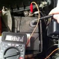
- UPS does not hold the load... First of all, you need to check how long the device can work without a network. If even a little worked out, then the problem is most likely in the loss of battery capacity. It is quite easy to check this by connecting a 100-watt incandescent lamp to the UPS as a load. The standard battery has a capacity of 7 A / h. A good battery will keep the lamp running for at least 20 minutes. If this time is reduced by half, then the battery should be replaced.
- UPS shuts down... Again, we sin on the battery. If the battery is okay and you are sure of its capacity, then the problem is in the electronics. Definitely - to the service center.
Our tips for self-repairing an uninterruptible power supply cover the most basic problems. If you are unsure of your knowledge and have no experience of "dealing" with equipment operating on hazardous voltages, it is best to consult a professional. You can familiarize yourself with the full list of repair and modernization services. If you have any unresolved problems with your PC, then feel free to contact the specialists of our company, we are always ready to take on any difficult work. We work both in the city of Chelyabinsk and in the region.
Our company has been servicing and repairing APC uninterruptible power supplies for over five years. Timely service of your APC uninterruptible power supply can greatly extend its life. If you want to save your nerves, time and money. In addition, untimely servicing of an APC UPS can not only damage the APC UPS itself, but also harm the health of personnel. This is why we recommend timely servicing your APC UPS.
The scope and frequency of service for an APC UPS is determined by the manufacturer's instructions and operating conditions. We strongly recommend that you service your APC UPS at least once a year.
It is important to remember that the service maintenance of the APC UPS at the stage of its commissioning consists in the fact that our engineer performs external inspection of the UPS, diagnostics, and commissioning. Also, our engineer monitors the passage of the self-diagnosis cycle of the APC UPS, configures the most suitable operating parameters, and, if necessary, personnel training.
Service maintenance of APC uninterruptible power supplies includes: on-site visit to the customer, carrying out diagnostic work using APC service software, visual inspection of the UPS, preventing the APC uninterruptible power supply from contamination, replacing thermal interfaces if necessary, visual inspection of the APC UPS for electrolyte leaks from the battery, battery swelling and oxidized contacts. In addition, the service maintenance of the APC IDB includes monitoring the condition of electrical wires and connections, monitoring the condition and performance of the power elements of the APC uninterruptible power supply, monitoring the condition and performance of the cooling system, monitoring the condition of APC batteries. Check and, if necessary, adjust: rectifier module, battery charging module, inverter module, internal settings and operating parameters of the APC UPS, self-diagnostic system operability. After these maintenance work on the APC UPS, measurements are made of the electrical parameters of the APC uninterruptible power supply, and the internal measuring circuits are calibrated. After all the work on setting and calibrating the operating parameters of the APC UPS, our specialist draws up an act on the status of the UPS with recommendations for further operation.
BSM Technologies LLC is pleased to offer you its services for installation, post-warranty and routine maintenance of APC UPS of various types and configurations, as well as repair services for APC uninterruptible power supplies. All work will be completed as quickly and efficiently as possible in accordance with the work schedule.
The service contract for the maintenance of APC uninterruptible power supplies necessarily includes such important points as the frequency of work, the inclusion of spare parts in the contract price, the inclusion of the cost of repair work in the contract price, the response time of service engineers in the event of a failure of the APC uninterruptible power supply, the need round-the-clock telephone support of a service engineer, repair time if necessary.
Call us by phone and our manager will advise you on any issue related to service and repair of APC uninterruptible power supplies.
Sources have long taken the place of a necessary component in modern computer systems and sets of other devices used both in enterprises and at home. Many consumers are familiar with the features of operation and types of UPS. For them, the usual for a computer or, for example, specialized uninterruptible power supplies for boilers are not something new and unfamiliar. Especially on the territory of our country, where the power grids, to say nothing, are not characterized by the stability of indicators issued to end users. And the supply of electricity, it's no secret to anyone, can be unexpectedly cut off, albeit for a short time, but at any moment.
Such a useful and necessary UPS
Before proceeding to consider the possibilities of repairing the UPS with your own hands, and this will be discussed below, the importance of these devices should be noted once again. Uninterruptible devices are a kind of barrier between devices that consume electricity and the troubles that instability of the electrical power supplied to the equipment can bring. Developers are constantly improving their products and making them more versatile.
Thus, the UPS device allows in most cases to organize fairly reliable protection not only of valuable user information in the case of a PC when the light is suddenly turned off, but also the hardware components of other devices that are sensitive to voltage surges or its disappearance. But even a device designed to protect other devices from damage can sometimes fail itself. Consider the main components that make up an uninterruptible power supply, as well as relatively easy UPS malfunctions.
UPS device
At their core, sources are rather complex electronic devices, consisting of many components. If you look at the UPS circuit, and almost any, you can find that the device consists of the components presented:
- converters;
- switches;
- electrical energy storage devices (in most cases - a storage battery).

Why do breakdowns occur
It is known that the more complex a system is, the more likely it is to fail due to the failure of one or more individual components. In general, the complexity of the UPS device is due to a rather wide range of functions that the device must perform. This includes not only the possibility of supplying energy to electrical devices at the time of loss of voltage in the network, but also stabilizing, protective functions. There are devices for which even broader requirements are imposed. For example, uninterruptible boilers for boilers must, in addition to the above, have a correct sinusoid at their output. This complexity of the system makes it possible for some malfunctions to occur, although this does not happen often. What to do in this case? How to repair a UPS with your own hands?
Precautionary measures
Before proceeding to manipulate the device, it should be borne in mind that the UPS is a complex electronic device and precautions must be taken when carrying out repair work. All operations with an uninterruptible power supply can be carried out only after making sure that the device is de-energized. No advice and secrets of UPS repair, heard from friends or found on the Internet, will not save you from electric shock in case of rash actions and careless handling of live components!

Where to begin?
Of course, a UPS, like any other electronic device, requires certain elementary rules to be followed during its operation. Very often, the cause of a malfunction that appears to the user is incorrectly connected wires, weakening or oxidation over time of their connection terminals, etc. powering the UPS, finally make sure that the power is available at the outlet.
Health support
In most cases, the device in question serves its owner for many years and without any particular problems. At the same time, to achieve this state of affairs, regular UPS maintenance is required, which consists in replacing the battery (approximately every two years) and general monitoring of the health of electronic components. If, to control the properties of capacitors, resistors and other electronic elements, you need a fairly deep knowledge in electronics and circuitry or a trip to a service center, then almost everyone can replace a UPS battery that has failed or lost its properties over time. Such a do-it-yourself UPS repair has to be carried out by almost every device owner at least once during the life cycle of an uninterruptible power supply.

Fuse
If the uninterruptible power supply does not turn on after a voltage drop or as a result of a short circuit in the supply network, it is likely that even disassembling it will not be required to restore the device to work. The first thing to do when repairing the UPS with your own hands is to check the integrity of the fuse and replace it if necessary. Since this component fails quite often, UPS manufacturers design their devices in such a way that the user can carry out the procedure himself. The spare fuses themselves are often included with the UPS. If they are not there, a protective element similar to the one removed from the device can be purchased at any store where radio components are sold. To replace the fuse, you need to find a special tray containing it on the case and remove / unscrew - depending on the design - the contents. Replace the tray after replacement. The procedure is described in more detail in the instructions for the UPS, but in general, any home master will figure it out without it.

Battery Replacement
It takes very little time to replace the battery and the only tool is a Phillips screwdriver. Initially, it is required to unscrew several screws that fasten the parts of the case and located at the bottom of the UPS, in special holes. This will remove the top cover and access the battery. In most cases, the battery is not fixed in any special way inside the case and can be easily removed. You just need to disconnect the two wires that are connected to the battery using the terminals. After removing the energy storage source from the UPS enclosure, it is necessary to identify its label and purchase a similar battery from a specialized store. The UPS is assembled in the reverse order:
- Installing the battery.
- Connect the wires, observing the polarity.
- Installation and connection of parts of the device body.

Difficult repair
If the above tips are followed, that is, the UPS is connected correctly, the fuse in the device is intact and the battery is working, and the UPS still does not work properly, probably the most correct solution would be to contact a service center for repair. The fact is that the UPS circuit is rather complicated for an ordinary user, diagnostics and replacement, if necessary, of individual electronic components without special tools and master skills at home are often simply unfeasible. Thus, trying to fix a non-working device without certain knowledge and skills, as well as without the availability of appropriate equipment, a home craftsman can only aggravate the situation.

In general, having decided to fix a faulty UPS on your own, you must first of all weigh your strengths and capabilities. From an ordinary user, most often it is required to carry out the simplest manipulations, which would be more correctly attributed to the maintenance of the device, and not its repair. It is better to entrust the elimination of complex breakdowns to professionals.
 Simple tips on how to test a transformer with a multimeter for operability
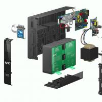 Repair of uninterruptible power supplies Commercial proposal for the repair of an uninterruptible power supply
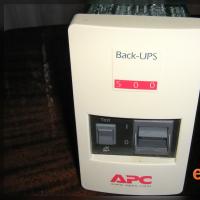 Do-it-yourself UPS repair: wizard's advice Repair of apc uninterruptible power supplies
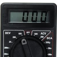 Repair of a multimeter m 830b does not show an ohmmeter
 Programs for drawing electrical circuits
 Drawing boards in Sprint-Layout correctly from the first steps
 What program can open the file