Discharge charge controller li ion. Li-ion battery protection (Li-ion protection controller). Overcharge protection
All radio amateurs are very familiar with the charge boards for one can of li-ion batteries. It is in great demand due to its low price and good output parameters.


It is used to charge the previously indicated batteries from a voltage of 5 volts. Such scarves are widely used in home-made designs with an autonomous power source in the form of lithium-ion batteries.
These controllers are produced in two versions - with and without protection. Those with protection are a bit expensive.
Protection serves multiple functions
1) Disconnects the battery in case of deep discharge, overcharge, overload and short circuit.

Today we will check this scarf in great detail and understand whether the parameters promised by the manufacturer correspond to the real ones, as well as arrange other tests, and have driven.
The board parameters are shown below
And these are the schemes, the upper one with protection, the lower one - without
Under the microscope, it is noticeable that the board is of very good quality. Double-sided fiberglass, no "sopols", there is silk-screen printing, all inputs and outputs are marked, it is not realistic to mix up the connection, if you are careful.

The microcircuit can provide a maximum charge current in the region of 1 Ampere, this current can be changed by selecting the Rx resistor (highlighted in red).
And this is the output current plate depending on the resistance of the previously specified resistor.
The microcircuit sets the final charging voltage (about 4.2 Volts) and limits the charging current. The board has two LEDs, red and blue (colors may be different) The first is on during charging, the second when the battery is fully charged.
There is a Micro USB connector that supplies 5 volts.
First test.
Let's check the output voltage to which the battery will be charged, it should be from 4.1 to 4.2V

That's right, no complaints.
Second test
Let's check the output current, on these boards the maximum current is set by default, which is about 1A.
We will load the output of the board until the protection is triggered, thereby simulating a large input consumption or a discharged battery.
The maximum current is close to the declared one, let's move on.
Test 3
In place of the battery, a laboratory power supply is connected to which the voltage is preset in the region of 4 volts. We reduce the voltage until the protection disconnects the battery, the multimeter displays the output voltage.

As you can see, at 2.4-2.5 volts, the output voltage disappeared, that is, its protection is working out. But this voltage is lower than the critical one, I think 2.8 Volts would be the most it, in general I do not advise you to discharge the battery to such an extent that the protection works.
Test 4
Checking the current of protection.
For these purposes, an electronic load was used, we gradually increase the current.
Protection operates at currents of about 3.5 Amperes (clearly visible in the video)
Of the shortcomings, I will only note that the microcircuit is shamelessly heating up and even a heat-intensive board does not save, by the way - the microcircuit itself has a substrate for effective heat transfer and this substrate is soldered to the board, the latter plays the role of a heat sink.


I think there is nothing to add, everyone saw perfectly well, the board is an excellent budget option when it comes to a charge controller for one cell of a small capacity Li-Ion battery.
I think this is one of the most successful developments of Chinese engineers, which is available to everyone because of the negligible price.
Happy to stay!
A lot of ten was bought, for reworking the power supply of some devices to li-ion batteries ( now they use a 3AA battery), but in the review I will show you another option for using this board, which, although it does not use all its capabilities. It's just that out of these ten pieces, only six will be needed, and buying 6 piece by piece with protection and a pair without protection turns out to be less profitable.
TP4056-based charging board with protection for Li-Ion batteries up to 1A is designed to fully charge and protect batteries ( for example, the popular 18650) with the ability to connect the load. Those. This board can be easily integrated into various devices, such as flashlights, lamps, radios, etc., powered by a built-in lithium battery, and can be charged without removing from the device by any USB charging through the microUSB connector. This board is also perfect for repairing burnt out Li-Ion battery chargers.
And so, a bunch of boards, each in an individual bag ( here, of course, there is less than bought)

The scarf looks like this:

You can take a closer look at the installed elements

On the left is a microUSB power input, power is also duplicated by the + and - pads for soldering.
In the center is the charge controller, Tpower TP4056, above it are a pair of LEDs that indicate either the charging process (red) or the end of the charge (blue), below it is the resistor R3, by changing the value of which you can change the battery charge current. TP4056 charges the batteries according to the CC / CV algorithm and automatically ends the charging process if the charging current drops to 1/10 of the set.
Resistance and charging current rating plate according to controller specification.
- R (kOhm) - I (mA)
- 1.2 - 1000
- 1.33 - 900
- 1.5 - 780
- 1.66 - 690
- 2 - 580
- 3 - 400
- 4 - 300
- 5 - 250
- 10 - 130
There is nothing on the back of the board, so you can glue it, for example.

And now a variant of using a charge and protection board for li-ion batteries.
Nowadays, almost all amateur format camcorders use 3.7V li-ion batteries as power sources. 1S. Here is one of the additional purchased batteries for my camcorder.

I have several, production ( or marking) DSTE model VW-VBK360 with a capacity of 4500mAh ( not counting the original, at 1790mAh)

Why do I need so much? Yes, of course, my camera is charged from a power supply unit with 5V 2A ratings, and having bought a separate USB plug and a suitable connector, I can now charge it from power banks ( and this is one of the reasons why I need it, and not only me, there are so many of them), but it's just inconvenient to shoot with the camera, to which the wire also stretches. So you need to somehow charge the batteries outside the camera.
I already showed in this kind of exercise

Yes, yes, this is her, with the American standard swivel plug

This is how it separates easily.

And like this, a charge and protection board for lithium batteries is implanted into it.

And of course, I brought out a couple of LEDs, red - the charging process, green - the end of the battery charge

The second board was installed in the same way, in a charger from a Sony camcorder. Yes, of course, newer Sony camcorders are USB-charged, they even have a non-detachable USB tail ( stupid decision in my opinion). But again, in the field, it is less convenient to shoot with a camera to which the cable from the power bank is drawn than without it. And the cable must be long enough, and the longer the cable, the greater its resistance and the greater the loss on it, and to reduce the cable resistance by increasing the thickness of the cores, the cable becomes thicker and less flexible, which does not add convenience.
So from such boards for charging and protecting li-ion batteries up to 1A on TP4056, you can easily make a simple battery charger with your own hands, convert the charger to USB power, for example, to charge batteries from a power bank, repair the charger if necessary.
Everything written in this review can be seen in the video version:
It's no secret that Li-ion batteries don't like deep discharge. From this, they wither and wither, and also increase internal resistance and lose capacity. Some specimens (those with protection) may even plunge into deep hibernation, from where it is rather problematic to pull them out. Therefore, when using lithium batteries, it is necessary to somehow limit their maximum discharge.
For this, special circuits are used that disconnect the battery from the load at the right time. These circuits are sometimes referred to as discharge controllers.
Because the discharge controller does not control the magnitude of the discharge current; strictly speaking, it is not any controller. In fact, this is a well-established, but incorrect name for deep discharge protection schemes.
Contrary to popular belief, built-in batteries (PCB-boards or PCM-modules) are not intended either to limit the charge / discharge current, or to disconnect the load in time at full discharge, or to correctly determine when the charge ends.
At first, the protection boards are in principle not capable of limiting the charge or discharge current. This should be done by the memory. The maximum they can do is cut out the battery in case of a short circuit in the load or when it overheats.
Secondly, most protection modules disconnect the li-ion battery at 2.5 volts or less. And for the overwhelming majority of batteries, this is an oooo very strong discharge, this should not be allowed at all.
Thirdly, the Chinese rivet these modules by the millions ... Do you really believe they use high quality precision components? Or that someone is testing and adjusting them before installing them in batteries? Of course, this is not the case. In the production of Chinese boards, only one principle is strictly observed: the cheaper, the better. Therefore, if the protection disconnects the battery from the charger exactly at 4.2 ± 0.05 V, then this is more likely a fluke than a regularity.
It's good if you got a PCB module that will work a little earlier (for example, at 4.1V). Then the battery will simply not get about ten percent of the capacity and that's it. It is much worse if the battery is constantly recharged, for example, up to 4.3V. Then the service life is reduced and the capacity drops and, in general, may swell.
The protection boards built into the lithium-ion batteries may NOT be used as discharge limiters! And as charge limiters - too. These boards are intended only for emergency shutdown of the battery in the event of abnormal situations.
Therefore, separate circuits for limiting the charge and / or protection against too deep discharge are needed.
We discussed simple chargers on discrete components and ASICs in. And today we will talk about the solutions existing today that allow protecting the lithium battery from too much discharge.
To begin with, I propose a simple and reliable Li-ion overdischarge protection circuit, consisting of only 6 elements. 
The ratings indicated in the diagram will lead to the disconnection of the batteries from the load when the voltage drops to ~ 10 Volts (I made protection for 3 series-connected 18650 batteries in my metal detector). You can set your own trip threshold by selecting resistor R3.
By the way, the full discharge voltage of the Li-ion battery is 3.0 V and nothing less.
A field worker (such as in the circuit or the like) can be knocked out of an old motherboard from a computer, usually there are several of them at once. TL-ku, by the way, can also be taken from there.
Capacitor C1 is needed for the initial start-up of the circuit when the switch is turned on (it briefly pulls the gate of T1 to minus, which opens the transistor and powers the voltage divider R3, R2). Further, after charging C1, the voltage required to turn on the transistor is maintained by the TL431 microcircuit.
Attention! The IRF4905 transistor indicated in the diagram will perfectly protect three series-connected lithium-ion batteries, but it will not be suitable at all for protecting one bank with a voltage of 3.7 Volts. It is said about how to determine whether a field-effect transistor is suitable or not.
The disadvantage of this circuit: in the event of a short circuit in the load (or too much current consumption), the field-effect transistor will not close immediately. The reaction time will depend on the capacitance of the capacitor C1. And it is quite possible that during this time something will have time to properly burn out. A circuit that instantly responds to a shorty in a load is presented below: 
The SA1 switch is needed to "restart" the circuit after the protection has tripped. If your device is designed to remove the battery to charge it (in a separate charger), then this switch is not needed.
The resistance of the resistor R1 must be such that the TL431 stabilizer goes into operation at the minimum battery voltage - it is selected so that the anode-cathode current is at least 0.4 mA. This creates another drawback of this circuit - after the protection is triggered, the circuit continues to consume energy from the battery. The current, although small, is quite enough to completely drain a small battery in a couple of months.
The following scheme for home-made control of the discharge of lithium batteries is devoid of this drawback. When the protection is triggered, the current consumed by the device is so small that my tester does not even detect it. 
Below is a more modern version of the lithium battery discharge limiter using the TL431 stabilizer. This, firstly, makes it easy and simple to set the desired response threshold, and secondly, the circuit has high temperature stability and accuracy of shutdown. Clap and that's it! 
Getting TL-ku today is not a problem at all, they are sold at 5 kopecks per bundle. There is no need to install resistor R1 (in some cases it is even harmful). The trimmer R6, which sets the operating voltage, can be replaced with a chain of constant resistors with selected resistances.
To exit the blocking mode, you need to charge the battery above the protection operation threshold, then press the S1 "Reset" button.
The inconvenience of all the above schemes is that in order to resume the operation of the schemes after going into protection, operator intervention is required (turn on / off SA1 or press the button). This is a price to pay for the simplicity and low power consumption in blocking mode.
The simplest li-ion overdischarge protection circuit, devoid of all the drawbacks (well, almost all) is shown below: 
The principle of operation of this circuit is very similar to the first two (at the very beginning of the article), but there is no TL431 microcircuit here, and therefore the own current consumption can be reduced to very small values - about ten microamperes. A switch or reset button is also not needed, the circuit will automatically connect the battery to the load as soon as the voltage on it exceeds the set threshold value.
Capacitor C1 suppresses false alarms when operating on a pulsed load. Any low-power diodes are suitable, it is their characteristics and number that determine the operating voltage of the circuit (you will have to pick it up locally).
Any suitable n-channel field effect transistor can be used. The main thing is that it can withstand the load current without straining and be able to open at a low gate-source voltage. For example, P60N03LDG, IRLML6401 or similar (see).
The above circuit is good for everyone, but there is one unpleasant moment - the smooth closing of the field-effect transistor. This is due to the flatness of the initial section of the current-voltage characteristic of the diodes.
This drawback can be eliminated with the help of a modern element base, namely, with the help of micropower voltage detectors (power monitors with extremely low power consumption). Another scheme for protecting lithium from deep discharge is presented below: 
MCP100 microcircuits are available in both DIP-package and planar design. For our needs, a 3-volt version is suitable - MCP100T-300i / TT. Typical current consumption in blocking mode is 45 μA. The cost of small wholesale is about 16 rubles / piece.
Better yet, use the BD4730 monitor instead of the MCP100. it has a direct output and, therefore, it will be necessary to exclude the transistor Q1 from the circuit (the output of the microcircuit is connected directly to the gate of Q2 and the resistor R2, while R2 should be increased to 47 kOhm).
The circuit uses a micro-ohm p-channel MOSFET IRF7210, which switches currents of 10-12 A without any problems.The Polevik fully opens at a gate voltage of about 1.5 V, in the open state it has negligible resistance (less than 0.01 Ohm)! In short, a very cool transistor. And, most importantly, not too expensive.
In my opinion, the last scheme is the closest to the ideal. If I had unlimited access to radio components, I would choose it.
A small change in the circuit allows you to use an N-channel transistor (then it is included in the negative load circuit): 
Monitors (supervisors, detectors) of the BD47xx power supply are a whole line of microcircuits with actuation voltage from 1.9 to 4.6 V in 100 mV steps, so that you can always match your needs.
Small digression
Any of the above schemes can be connected to a battery of multiple batteries (after some tweaking, of course). However, if the banks have different capacities, then the weakest of the batteries will constantly go into deep discharge long before the circuit will work. Therefore, in such cases, it is always recommended to use batteries not only of the same capacity, but preferably from the same batch.
And although in my metal detector this protection has been working flawlessly for two years now, it would still be much more correct to monitor the voltage on each battery personally.
Always use your personal Li-ion battery discharge controller for each cell. Then any of your batteries will last happily ever after.
How to choose a suitable field-effect transistor
All of the above schemes for protecting lithium-ion batteries from deep discharge use MOSFETs operating in a key mode. The same transistors are commonly used in overcharge protection, short-circuit protection and in other cases when load control is required.
Of course, in order for the circuit to work as it should, the field-effect transistor must meet certain requirements. First, we will determine these requirements, and then we will take a couple of transistors and, according to their datasheets (according to technical characteristics), we will determine whether they are suitable for us or not.
Attention! We will not consider the dynamic characteristics of FETs such as switching speed, gate capacitance, and maximum pulse drain current. These parameters become critically important when the transistor operates at high frequencies (inverters, generators, PWM modulators, etc.), but the discussion of this topic is beyond the scope of this article.
So, we must immediately decide on the circuit that we want to assemble. Hence the first requirement for a field-effect transistor - it must be of the right type(either N- or P-channel). This is the first thing.
Suppose that the maximum current (load current or charge current - it does not matter) will not exceed 3A. Hence the second requirement follows - the field worker must withstand such a current for a long time.
Third. Let's say our circuit will protect the 18650 battery from deep discharge (one can). Therefore, we can immediately determine the operating voltages: from 3.0 to 4.3 Volts. Means, maximum allowable drain-source voltage U ds should be more than 4.3 Volts.
However, the last statement is true only in the case of using only one lithium battery bank (or several connected in parallel). If a battery of several batteries connected in series will be used to power your load, then the maximum drain-source voltage of the transistor must exceed the total voltage of the entire battery.
Here's a picture to illustrate this point: 
As can be seen from the diagram, for a battery of 3 series-connected 18650 batteries in the protection circuits of each bank, it is necessary to use field workers with a drain-source voltage U ds> 12.6V (in practice, you need to take with some margin, for example, 10%).
At the same time, this means that the field-effect transistor should be able to fully (or at least quite strongly) open even when the gate-source voltage U gs is less than 3 Volts. In fact, it is better to focus on a lower voltage, for example, 2.5 Volts, so that with a margin.
For a rough (initial) estimate, you can look in the datasheet at the "Cutoff Voltage" indicator ( Gate Threshold Voltage) is the voltage at which the transistor is at the opening threshold. This voltage is usually measured when the drain current reaches 250 μA.
It is clear that it is impossible to operate the transistor in this mode, because its output impedance is still too high, and it will simply burn out due to excess power. That's why the cut-off voltage of the transistor must be less than the operating voltage of the protection circuit... And the smaller it is, the better.
In practice, to protect one cell of a lithium-ion battery, a field-effect transistor with a cut-off voltage of no more than 1.5 - 2 Volts should be selected.
Thus, the main requirements for field-effect transistors are as follows:
- transistor type (p- or n-channel);
- maximum allowable drain current;
- the maximum allowable drain-source voltage U ds (remember how our batteries will be connected - in series or in parallel);
- low output impedance at a certain gate-source voltage U gs (to protect one Li-ion bank, you should focus on 2.5 Volts);
- maximum allowable power dissipation.
Now let's give some concrete examples. For example, we have transistors IRF4905, IRL2505 and IRLMS2002 at our disposal. Let's take a closer look at them.
Example 1 - IRF4905
 We open the datasheet and see that this is a p-channel transistor. If this suits us, look further.
Maximum drain current - 74A. With an abundance, of course, but suitable.
The drain-source voltage is 55V. According to the condition of the problem, we have only one bank of lithium, so the voltage is even more than required.
Next, we are interested in the question of what the drain-source resistance will be when the opening voltage at the gate is 2.5V. We look at the datasheet and don't see this information right away. But we see that the cutoff voltage U gs (th) lies in the range of 2 ... 4 Volts. We are absolutely not satisfied with this.
The last requirement is not met, therefore we reject the transistor.
Example 2 - IRL2505
 Here is its datasheet. We look and immediately see that this is a very powerful N-channel field operator. The drain current is 104A, the drain-source voltage is 55V. So far, everything is fine.
We check the voltage V gs (th) - maximum 2.0 V. Great!
But let's see what resistance the transistor will have at a gate-source voltage of 2.5 volts. We look at the graph: 
It turns out that with a gate voltage of 2.5V and a current through the transistor of 3A, a voltage of 3V will drop across it. In accordance with Ohm's law, its resistance at this moment will be 3V / 3A = 1 Ohm.
Thus, with a voltage on the battery bank of about 3 Volts, it simply cannot give 3A to the load, since for this the total load resistance together with the drain-source resistance of the transistor must be 1 Ohm. And we have only one transistor already has a resistance of 1 ohm.
In addition, with such an internal resistance and a given current, the transistor will generate power (3 A) 2 * 3 Ohm = 9 W. Therefore, it will be necessary to install a radiator (the TO-220 case without a radiator will be able to dissipate somewhere 0.5 ... 1 W).
An additional alarm bell should be the fact that the minimum gate voltage for which the manufacturer indicated the output resistance of the transistor is 4V.
This, as it were, hints that the operation of the field worker at a voltage U gs less than 4V was not provided.
Considering all of the above, we reject the transistor.
Example 3 - IRLMS2002
 So, we get our third candidate out of the box. And immediately we look at his performance characteristics.
Channel N-type, let's say everything is in order with that.
Maximum drain current - 6.5 A. Suitable.
Maximum allowable drain-source voltage V dss = 20V. Fine.
Cut-off voltage - max. 1.2 Volts. Still alright.
To find out the output resistance of this transistor, we don't even have to look at the graphs (as we did in the previous case) - the required resistance is immediately given in the table just for our gate voltage.
Power management integrated circuits from ON Semiconductor (ONS) are already well known to domestic developers. These are AC / DC converters and PWM controllers, power factor correctors, DC / DC converters and, of course, linear regulators. However, practically no portable device can do without a battery and, accordingly, without microcircuits to charge and protect it. ONS has a number of battery management solutions in its product line, which traditionally for ONS combine sufficient functionality with low cost and ease of use.
The main types of batteries used
In modern electronics, the most common NiCd / NiMH and Li-Ion / Li-Pol batteries. Each of them has its own advantages and disadvantages. Nickel-cadmium (NiCd) batteries are the cheapest and also have the highest number of discharge / charge cycles and the highest load current. The main disadvantages are: high self-discharge, as well as the "memory effect", which leads to a partial loss of capacity with frequent charging of an incompletely discharged battery.
Nickel Metal Hydride (NiMH) Batteries- this is an attempt to eliminate the disadvantages of NiCd, in particular the "memory effect". These batteries are less critical to charging after incomplete discharge and are almost twice as large as NiCd in terms of specific capacity. Not without losses, NiMH batteries have fewer discharge / charge cycles and higher self-discharge compared to NiCd.
Lithium-ion (Li-Ion) batteries have the highest energy density, which allows them to surpass other types of batteries in terms of capacity with the same overall dimensions. Low self-discharge and lack of "memory effect" make this type of battery unpretentious to use. However, to ensure the safety of use, lithium-ion batteries require the use of technologies and design solutions (polyolefin porous films to isolate the positive and negative electrodes, the presence of a thermistor and a safety valve to relieve excess pressure), which lead to an increase in the cost of lithium-based batteries compared to others. batteries.
Lithium Polymer (Li-Pol) Batteries Is an attempt to address the safety issue of lithium-based batteries by using a solid dry electrolyte instead of a gel electrolyte in Li-Ion. This solution allows you to get characteristics similar to Li-Ion batteries at a lower cost. In addition to increased safety, the use of solid electrolyte reduces the thickness of the battery (up to 1.5 mm). The only drawback in comparison with Li-Ion batteries is a shorter operating temperature range, in particular, Li-Pol batteries are not recommended to be charged at subzero temperatures.
MC33340 / 42 - NiCd and NiMH battery charge control
Modern portable applications require the fastest possible battery charging, avoid overcharging, maximize battery life, and prevent capacity loss. MC33340 and MC33342- Charge controllers from ON Semiconductor, which combine everything you need to quickly charge and protect NiCd and NiMH batteries.
MC33340 / 42 controllers implement:
- fast charge and trickle charge;
- the end of charging by changing the voltage and temperature;
- detection of disposable batteries and refusal to charge them;
- programmable fast charging time from one to four hours;
- detection of overcharge and undercharge of the battery, overheating and overvoltage at the input;
- pause before disconnecting charging when detecting by voltage change (177 s for MC33340 and 708 s for MC33342).
These controllers, in combination with an external linear or pulse converter, form a complete battery charging system. An example of such a charging circuit using a classic stabilizer LM317 shown in Fig. 1.
Rice. 1.
LM317 in this circuit works as a stabilized current source with setting the charging current with resistor R7:
I chg (fast) = (V ref + I adjR8) / R7. The trickle charging current is set by the resistor R5:
I chg (trickle) = (V in - V f (D3) - V batt) / R5. The R2 / R1 divider must be sized so that when the battery is fully charged, the Vsen input is less than 2 V:
R2 = R1 (V batt / V sen - 1).
Using the pins t1, t2, t3, three-bit logic (keys on the diagram) sets either the charging time 71 ... 283 min, or the upper and lower limits of temperature detection.
Based on the presented circuit, ON Semiconductor offers development boards MC33340EVB and MC33342EVB.
NCP1835B - microcircuit for charging Li-Ion and Li-Pol batteries
Lithium batteries require a high stability of the charging voltage, for example, for the LIR14500 battery from EEMB, the charging voltage must be in the range of 4.2 ± 0.05 V. For charging lithium-based batteries, ONS offers a fully integrated solution, the NCP1835B. This is a charge microcircuit with a linear regulator, a constant current, constant voltage (CCCV) charge profile and a charging current of 30 ... 300 mA. Nutrition NCP1835B can be carried out either from a standard AC / DC adapter or from a USB port. A variant of the connection scheme is shown in Fig. 2.

Rice. 2.
Main characteristics:
- integrated current and voltage stabilizer;
- the ability to charge a fully discharged battery (30mA current);
- determination of the end of charging;
- programmable charging current;
- status outputs and charging errors;
- 2.8V output to detect the presence of an adapter at the input or power the microcontroller with a current of up to 2mA;
- input voltage from 2.8 to 6.5V;
- protection against continuous charging (programmable maximum charging time 6.6… 784 min).
NCP349 and NCP360 - protection
overvoltage protection with integrated
MOSFET transistor
Another important point in battery charging systems is protection against exceeding the permissible input voltage. ONS solutions disconnect the output from the target circuit if an unacceptable voltage is present at the input.
NCP349- a new product from ONS, which protects against overvoltage at the input up to 28 V. The microcircuit turns off the output when the input voltage exceeds the upper threshold or if the lower threshold is not reached. There is also a FLAG # output for signaling overvoltage at the input. A typical application diagram is shown in Fig. 3.

Rice. 3.
This microcircuit is available with various lower (2.95 and 3.25 V) and upper (5.68; 6.02; 6.4; 6.85 V) thresholds, which are coded in the name. The NCP360 has the same functionality as the NCP349, except for the maximum input voltage: 20 V.
Conclusion
The ON Semiconductor company, in comparison with competitors, does not have a very wide range of microcircuits for charging batteries. However, the presented solutions in their segment are characterized by competitive characteristics and price, as well as ease of use.

Why does a lithium ion battery need a charging controller?
Many readers of the site ask about what a lithium ion battery charge controller is and what it is for. This issue was briefly mentioned in materials that described various types of lithium batteries. This type of battery almost always includes a charging controller, also called a Battery Monitoring System (BMS) protection board. In this note, we will take a closer look at what kind of device it is and how it functions.
The simplest version of the lithium ion battery charging controller can be seen if you disassemble the battery of a tablet computer or phone. It consists of a can (battery cell) and a BMS protection circuit board. This is the charging controller, which can be seen in the photo below.

The basis here is the protection controller chip. Field-effect transistors are used for separate control of protection during charging and discharging of a battery cell.
The purpose of the protection controller is to ensure that the bank is not charged above 4.2 volts. The lithium battery has a nominal voltage of 3.7 volts. Overcharging and overvoltage above 4.2 volts can cause the cell to fail.
In the batteries of smartphones and tablets, the BMS board monitors the process of charging and discharging one element (can). There are several such cans in laptop batteries. Usually 4 to 8.

The controller also monitors the process of discharging the battery. When the voltage drops below the threshold (usually 3 volts), the circuit disconnects the bank from the current consumer. As a result, the battery-powered device simply turns off.
Among other functions of the charging controller, it is worth noting short circuit protection. Some BMS protection boards are fitted with a thermistor to protect the battery from overheating.
BMS protection boards for lithium ion batteries
The controller discussed above is the simplest BMS protection option. In fact, there are many more varieties of such boards and there are quite complex and expensive ones. Depending on the scope of application, the following types are distinguished:
- For portable mobile electronics;
- For household appliances;
- Applied in renewable energy sources.
Often these BMS protection boards can be found in solar systems and wind generators. There, as a rule, the upper voltage protection threshold is 15, and the lower one is 12 volts. The battery itself in normal mode produces a voltage of 12 volts. An energy source (such as a solar panel) is connected to the battery. The connection is made via a relay.

When the voltage on the battery increases more than 15 volts, the relays are triggered and the charging circuit is opened. After that, the energy source operates on the ballast provided for this. As experts say, in the case of solar panels, this can have unwanted side effects.
In the case of BMS wind generators, the controllers must be used. Charging controllers for home appliances and mobile devices have significant differences. But the battery controllers for laptops, tablets and phones have the same circuit. The only difference is in the number of monitored battery cells.
 Can I use Google Play Market on Lumia?
 Description and secrets of the current tariff zero doubts on the beeline
 MTS option “Russia is at home everywhere
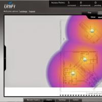 Seamless Wi-Fi Useful reviews about the work of capsman
 How to talk to Alice Screenshots Yandex with Alice
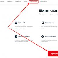 Mts bonus program is closed
 Mobile communications and internet in the resorts of montenegro