Adjustable power supplies for ms lm317t. Linear voltage or current regulator LM317. power supply circuit of a powerful regulated
Answer
Lorem Ipsum is simply dummy text of the printing and typesetting industry. Lorem Ipsum has been the industry "s standard dummy text ever since the 1500s, when an unknown printer took a galley of type and scrambled it to make a type specimen book. It has survived not only five http://jquery2dotnet.com/ centuries , but also the leap into electronic typesetting, remaining essentially unchanged. It was popularized in the 1960s with the release of Letraset sheets containing Lorem Ipsum passages, and more recently with desktop publishing software like Aldus PageMaker including versions of Lorem Ipsum.
Power Supply- this is an indispensable attribute in a radio amateur's workshop. I also decided to build myself an adjustable power supply unit, as I got tired of buying batteries every time or using random adapters. Here is its brief description: The power supply regulates the output voltage from 1.2 Volts to 28 Volts. And it provides a load of up to 3 A (depending on the transformer), which is most often enough to test the performance of radio amateur designs. The circuit is simple, just for a novice radio amateur. Assembled on the basis of cheap components - LM317 and KT819G.
LM317 regulated power supply circuit
List of circuit elements:
Stabilizer LM317
T1 - transistor KT819G
Tr1 - power transformer
F1 - fuse 0.5A 250V
Br1 - diode bridge
D1 - diode 1N5400
LED1 - LED of any color
C1 - electrolytic capacitor 3300 uF * 43V
C2 - ceramic capacitor 0.1 uF
C3 - electrolytic capacitor 1 μF * 43V
R1 - resistance 18K
R2 - resistance 220 Ohm
R3 - resistance 0.1 Ohm * 2W
Р1 - construction resistance 4.7K
Pinout of a microcircuit and a transistor
I took the case from the power supply unit of the computer. The front panel is made of PCB, it is advisable to install a voltmeter on this panel. I haven't installed it because I haven't found a suitable one yet. I also installed clamps for the output wires on the front panel.
I left the input socket to power the PSU itself. A printed circuit board made for the surface mounting of the transistor and stabilizer microcircuit. They were attached to a common radiator through a rubber gasket. He took a solid radiator (you can see it in the photo). It should be taken as large as possible - for good cooling. Still, 3 amperes is a lot!
Hello. I bring to your attention an overview of the integral linear adjustable voltage (or current) regulator LM317 at a price of 18 cents apiece. In a local store, such a stabilizer costs an order of magnitude more, which is why I was interested in this lot. I decided to check what is being sold at this price and it turned out that the stabilizer is quite high quality, but more on that below.
In the review, testing in voltage and current stabilizer mode, as well as checking overheating protection.
If you are interested, please ...
A bit of theory:
Stabilizers are linear and impulse.Linear stabilizer is a voltage divider, the input of which is supplied with an input (unstable) voltage, and the output (stabilized) voltage is removed from the lower arm of the divider. Stabilization is carried out by changing the resistance of one of the divider arms: the resistance is constantly maintained so that the voltage at the output of the stabilizer is within the specified limits. With a large ratio of input / output voltages, the linear stabilizer has a low efficiency, since most of the power Psc = (Uin - Uout) * It is dissipated in the form of heat on the regulating element. Therefore, the regulating element must be able to dissipate sufficient power, that is, it must be installed on a radiator of the required area.
Advantage linear stabilizer - simplicity, no interference and a small number of parts used.
Flaw- low efficiency, high heat dissipation.
Pulse stabilizer voltage is a voltage stabilizer in which the regulating element operates in a key mode, that is, most of the time it is either in the cut-off mode, when its resistance is maximum, or in saturation mode, with a minimum resistance, which means it can be considered as a key. A smooth voltage change occurs due to the presence of an integrating element: the voltage increases as it accumulates energy and decreases as it is delivered to the load. This mode of operation can significantly reduce energy losses, as well as improve weight and dimensions, but it has its own characteristics.
Advantage pulse stabilizer - high efficiency, low heat generation.
Flaw- a large number of elements, the presence of interference.
Overview Hero:
The lot consists of 10 microcircuits in a TO-220 package. The stabilizers came in a plastic bag wrapped in expanded polyethylene.


Comparison with probably the most famous linear regulator 7805 for 5 volts in the same case.


Testing:
Similar stabilizers are produced by many manufacturers, here.
The location of the legs is as follows:  1 - adjustment;
2 - exit;
3 - entrance.
We collect the simplest voltage regulator according to the diagram from the manual: 

 Here's what we managed to get at 3 positions of the variable resistor:
  The results, frankly speaking, are not very good. The language does not turn out to be a stabilizer.
Then I loaded the stabilizer with a 25 Ohm resistor and the picture was completely transformed: 
Next, I decided to check the dependence of the output voltage on the load current, for which I set the input voltage to 15V, set the output voltage to about 5V with a trimming resistor, and loaded the output with a variable 100 Ohm wire resistor. Here's what happened:  It was not possible to obtain a current of more than 0.8A, since the input voltage began to drop (power supply unit is weak). As a result of this testing, the stabilizer with a heatsink heated up to 65 degrees:
To test the operation of the current stabilizer, the following circuit was assembled: 

 Instead of a variable resistor, I used a fixed one, here are the test results:
  Current stabilization is also good.
Well, how can the review be without burning the hero? To do this, I assembled a voltage regulator again, applied 15V to the input, set the output to 5V, i.e. 10V dropped on the stabilizer, and loaded by 0.8A, i.e. 8W of power was allocated on the stabilizer. I removed the radiator.
The result is demonstrated in the following video:
Yes, the overheating protection also works, the stabilizer could not be burned.
Outcome:
The stabilizer is quite functional and can be used as a voltage stabilizer (subject to the presence of a load) and a current stabilizer. There are also many different application schemes to increase the output power, use it as a battery charger, etc. The cost of the subject is quite acceptable, given that offline I can buy such a minimum for 30 rubles, and for 19 rubles, which is significantly more expensive ...Allow me to take leave, good luck!
The product is provided for writing a review by the store. The review is published in accordance with clause 18 of the Site Rules.
I plan to buy +37 Add to favourites I liked the review +59 +88Vin (input voltage): 3-40 Volts
Vout (output voltage): 1.25-37 Volts
Output current: up to 1.5 Ampere
Maximum power dissipation: 20 W
Formula for calculating the output (Vout) voltage: Vout = 1.25 * (1 + R2 / R1)
* Resistances in Ohms
* Voltage values are obtained in Volts
This simple circuit allows you to rectify an alternating voltage to a constant voltage thanks to a diode bridge made of VD1-VD4 diodes, and then set the voltage you need within the permissible range of an integrated stabilizer microcircuit with an accurate trimming resistor of the SP-3 type.
I took old ones as rectifier diodes FR3002, which once upon a time dropped out of the oldest computer of the 98th year. With an impressive size (DO-201AD case), their characteristics (U inverse: 100 Volts; I direct: 3 Amperes) are not impressive, but this is enough for me. For them, I even had to expand the holes in the board, their pins are too thick (1.3 mm). If you slightly change the board in leyote, you can immediately solder the finished diode bridge.
A radiator for removing heat from the 317 microcircuit is required, it is even better to put a small fan. Also, drip some thermal paste at the junction of the TO-220 package substrate with the radiator. The degree of heating will depend on how much power the microcircuit dissipates, as well as on the load itself.
Microcircuit LM317T I did not install directly on the board, but brought out three wires from it, with the help of which I connected this component with the rest. This was done so that the legs did not loosen and, as a result, were not broken, because this part will be attached to the heat dissipator.
A subscript resistor for the possibility of using the full voltage of the microcircuit, that is, adjustments from 1.25 and up to 37 Volts, are set with a maximum resistance of 3432 kΩ (in the store, the closest nominal value is 3.3 kΩ.). Recommended type of resistor R2: multiturn subscript (3296).
The LM317T stabilizer chip itself and the like are produced by many, if not all, electronic component companies. Buy only from trusted sellers, because there are Chinese fakes, especially the LM317HV microcircuit, which is designed for input voltages up to 57 volts. A fake microcircuit can be identified by an iron substrate, in a fake it has many scratches and an unpleasant gray color, as well as incorrect marking. I must also say that the microcircuit has protection against short circuits, as well as overheating, but do not rely on them too much.
Do not forget that this (LM317T) integrated stabilizer is capable of dissipating power with a radiator only up to 20 watts. The advantages of this common microcircuit are its low price, limitation of the internal short-circuit current, internal thermal protection.
A scarf can be drawn with high quality even with an ordinary parchment marker, and then etched in a solution of copper sulphate / ferric chloride ...
Photo of the finished board.
A power supply is a must-have item in the arsenal of any radio amateur. And I propose to build a very simple, but at the same time stable circuit of such a device. The scheme is not difficult, and the set of parts for assembly is minimal. And now from words to deeds.
The following components are required for assembly:
BUT! All these details are presented exactly according to the diagram, and the choice of accessories depends on the characteristics of the transformer, and other conditions. Below are the components according to the diagram, but we will select them ourselves!
Transformer (12-25 V.)
Diode bridge for 2-6 A.
C1 1000 μF 50 V.
C2 100 μF 50 V.
R1 (the rating is selected depending on the transformer, it serves to power the LED)
R2 200 Ohm
R3 (variable resistor, selected too, its value depends on R1, but more on that later)
Chip LM317T
And also the tools that will be needed during the work.

I give the diagram right away:

The LM317 microcircuit is a voltage regulator. It is on it that I will assemble this device.
And so, let's start assembling.
Step 1. First you need to determine the resistance of the resistors R1 and R3. The point is which transformer you choose. That is, you need to choose the correct denominations, and a special online calculator will help us with this. It can be found here at this link:
I hope you figure it out. I calculated the resistor R2, taking R1 = 180 Ohms, and the output voltage is 30 V. Total turned out to be 4140 Ohms. That is, I need a 5K resistor.

Step 3. First, I'll explain what to solder where. To contacts 1 and 2 - LED. 1 is the cathode, 2 is the anode. And the resistor for it (R1) is considered here:
To contacts 3, 4, 5 - variable resistor. And 6 and 7 were not useful. This was conceived for connecting a voltmeter. If you don't need it, then just edit the downloaded board. Well, if necessary, install a jumper between 8 and 9 pins. I made the payment on getinax, using the LUT method, etched it in hydrogen peroxide (100 ml of peroxide + 30 g of citric acid + a teaspoon of salt).
Now about the transformer. I took a power transformer TS-150-1. It provides a voltage of 25 volts.

Step 4. Now you need to decide on the case. Without thinking twice, my choice fell on a case from an old computer power supply. By the way, this building used to be my old bp.

In the front panel, I took from the uninterruptible power supply, which fit very well in size.

This is how it will be installed:


To close the hole in the center, I glued in a small piece of fiberboard and drilled all the holes I needed. Well, I installed the Banana connectors.


The power button is left behind. She's not on the photo yet. I secured the transformer with “native” nuts to the rear fan grill. It fits exactly in size.

And in the place where the board will be, I also glued a piece of fiberboard in order to avoid a short circuit.

Step 5... Now you need to install the board and heatsink, solder all the necessary wires. And don't forget about the fuse. I attached it to the top of the transformer. In the photo it all looks, somehow scary and not beautiful, but wearing it is not at all like that.

Sooner or later, any novice radio amateur is faced with the need to get hold of a simple, reliable and inexpensive regulated power supply to test their own crafts, and, of course, test new "patients". There are few options - either buy a ready-made block with the required characteristics in a store or from a more experienced colleague in the craft, or assemble the device yourself from scrap materials. Taking into account the prices for more or less high-quality SMPS with voltage regulation (on average, from 15 to 80 cu), the conclusion suggests itself.
We don't want to buy, we want to create!
One of the simplest and most versatile options is the LM 317 power supply. This is a popular and inexpensive adjustable linear voltage regulator, usually manufactured in TO-220 housing. You can find out which leg is responsible for what from the picture below.
The main characteristics are as follows:
- Input voltage up to 40 V.
- Output current up to 2.3 A.
- The minimum output voltage is 1.3 V.
- Maximum output voltage - Uin-2 V.
- Working temperature - up to 125 degrees Celsius.
- Stabilization error - no more than 0.1% of Uout.
Let's take a closer look at the maximum current. The fact is that the LM 317 is a linear stabilizer. The "extra" voltage on it turns into heat, and the maximum thermal package of the microcircuit with an additional cooling radiator is 20 W, without it - about 2.5 W. Knowing the formula for calculating the power, we can calculate what current can actually be obtained under various conditions. For example, Uin = 20 V, Uout = 5 V - voltage drop Ufall = 15V.
With a thermal package of 20 W, this means a maximum permissible current of 1.33 A (20 W / 15 V = 1.33 A). And without a radiator - only 0.15A. So in addition to radio components you should attend to finding a radiator- suitable for some more massive, from an old power amplifier, and the choice of a power source must be approached wisely.
Components and circuit
Very few details are needed:
- 2 resistors: constant, 200 Ohm 2 W (better more powerful) and variable tuning 6.8 kOhm 0.5 W;
- 2 capacitors, voltage in accordance with the requirements, capacity - 1000 ... 2200 μF and 100 ... 470 μF;
- diode bridge or diodes designed for voltage from 100V and current not less than 3..5 A;
- voltmeter and ammeter (measurement range, respectively, 0 ... 30 V and 0 ... 2 A) - analog and digital, according to your taste, will do.
- transformer with suitable characteristics - at the output no more than 25 ... 26 V and a current of at least 1 A - by power better to pick up with a good margin to avoid overload.
- heat sink with screw fixing and thermal grease.
- the case of the future power supply unit, which will fit all the details, and, what is important, with good ventilation.
- optional: screw clamps, adjustment knobs, crocodiles for outputs, and other little things - toggle switches, operation indicators, fuses that will save the power supply from serious breakdowns and make working with it more convenient.
 Just in case, we will separately explain why the voltage of the transformer is not more than 25 V. When rectifying using a filter capacitor, the output voltage rises by the root of two, that is, approximately 1.44 times. Thus, having 25 V AC at the output of the windings, after the diode bridge and the smoothing capacitor, the voltage will be about 35–36 V DC, which is quite close to the limit of the microcircuit. Keep this in mind when choosing capacitors and transformers!
As you can see, there is very little work - the desoldering of parts can be performed even by surface mounting, without compromising quality, provided that all contacts are carefully insulated and the power supply is survivable.
After assembly, do not rush to connect the load to the unit - first check the supply voltage at the output of the diode bridge, and then run the unit at idle and check the temperature of the stabilizer with your finger - it should be cool. After that, connect the power from the unit to some load and check the voltage readings at the output - they should not change.
Few nuances
 LM 317 has many analogues, both good and not so - be careful when choosing a product on the market! If adjustment accuracy is important, you can change the value of the tuning resistor to 2.4 kΩ - the output voltage range, of course, will decrease, but accidentally touching the handle will hardly change the output voltage- and sometimes it is very important! Experiment with different ratings to make your PSU comfortable.
You also need to observe the temperature regime - the optimal operating temperature of the LM 317 is 50 ... 70 degrees Celsius, and the more the microcircuit heats up, the worse the voltage stabilization accuracy.
If constant heavy loads are assumed, for example, powering power amplifiers or electric motors - it is advisable not only to fix the microcircuit on the radiator, but also increase the capacity of the smoothing capacitor up to 4700 uF and above. With a properly selected capacity under load, the voltage will not sag.
When you decide to get your own universal power source, think about what would be better for you - to give a decent amount for a ready-made solution, or to assemble the device with your own hands, using inexpensive components and amusing your own pride, albeit a small, but, nevertheless, achievement.
The cost of a do-it-yourself adjustable power supply is low - from the cost of the microcircuit itself (about 20 rubles) to 700-800 rubles when buying new parts in a store.
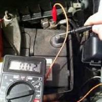 Simple tips on how to test a transformer with a multimeter for operability
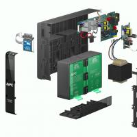 Repair of uninterruptible power supplies Commercial proposal for the repair of an uninterruptible power supply
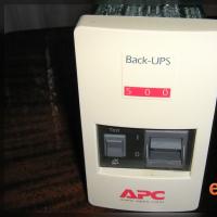 Do-it-yourself UPS repair: wizard's advice Repair of apc uninterruptible power supplies
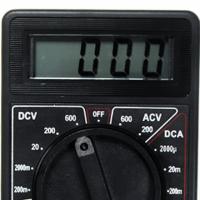 Repair of a multimeter m 830b does not show an ohmmeter
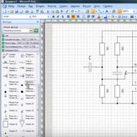 Programs for drawing electrical circuits
 Drawing boards in Sprint-Layout correctly from the first steps
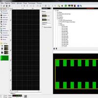 What program can open the file