Download tube amplifier circuits. Datagor Practical Electronics Magazine. Circuits with transistors
The amplifier is made on the basis of industrial UPV-1.25 units (with a power of 1250 W). It provided sound broadcasting in small cities or in areas of large cities. In the proposed amplifier, designed for sounding a disco hall, a soft amplitude limiting characteristic and small harmonic distortion are achieved.
Modern audio amplifiers with an output power of 1000 ... 2000 W are built on transistors. A tube amplifier of such power has a total weight of 150 ... 200 kg and its dimensions are much larger, which makes it inconvenient for transportation. But if it is used stationary in the same room, this disadvantage is less noticeable.
A tube amplifier made for a club disco, with its relative simplicity, provides high-quality sound through a speaker system distributed throughout the hall. The sound path is completely made on lamps, and the power supply is made according to the classic transformer scheme. Only two high-power GU-81 M lamps with a directly heated cathode were used as output lamps.
The amplifier is made on the basis of the amplifier units developed in the 70s for wire broadcasting - UPV-1.25 (power 1250W). It was installed in regional communication centers and it provided sound broadcasting in small regional cities or in areas of large cities. The design features of this amplifier made it very reliable and durable in operation: it was turned on in the morning at 6 pm, and turned off at 24 hours when the broadcast ended. Thus, he worked for years for 18 hours a day.
I had to make changes to the amplifier design to improve its parameters and match the output voltage to the load, and it was more convenient to service and move. First, I rewound the secondary winding of the output transformer, since in the factory version the output voltage was 240 V. Then I changed the design, collecting the amplifier in two blocks (photo in fig. 1) connected by a cable with a connector (amplifier unit and high-voltage power supply). The power supply circuit has been changed. Measures have been taken to expand the bandwidth, and the transistors used in the driver of the pre-final amplifier have been eliminated. The preamplifier is also assembled on tubes with a mixer for two inputs and a microphone amplifier. The result is an amplifier with good performance for high output power UMZCH.
Amplifier Specifications:
- Maximum / rated output power, W 1200/1000;
- Load resistance, Ohm 8 ... 16;
- Noise level, dB -80;
- Passband with uneven frequency response 1.5 dB, Hz 25 ... 20000;
- Harmonic coefficient,%:
- in the band 60 ... 400 Hz 1.5;
- 400 ... 6000 Hz 1;
- 6000 ... 16000 Hz 1.5.
Description of the amplifier and power supply
Preamplifier (fig. 2) consists of a microphone amplifier on the VL1 tube, two identical stages on the VL2, VL3 tubes, tone controls, amplification and a mixer on the VL4 tube. The amplifier has no special features, but the pre-amplifier tubes are heated by direct current.
Pre-terminal amplifier UMZCH (fig. 3) contains three lamps - VL5 - VL7. An amplifier with a load in the form of a transformer T1, which creates paraphase signals, is assembled on VL5 triodes. The separating capacitor C27 eliminates the magnetization of the magnetic circuit of the transformer. This is followed by two amplifying stages, assembled according to a push-pull circuit on lamps VL6, VL7 (6Н8С, 6Н6П).
To obtain the required anode current pulse at a low voltage on the screen grids, a voltage of about 700 V is applied to the pentode grids of the VL8, VL9 lamps. R71, R69 and R72, R70. Capacitors C28-C31, C34-C37, C40-C45 provide the necessary correction of the frequency response of the steps covered by the OOS. To increase the stability of the amplifier beyond the bandwidth, the primary winding of the output transformer is shunted by circuits C41R67 and C42R68; for the same purpose, resistors R60 and R64 are connected in series in the control grids circuits VL8 and VL9. A voltage of 3500 V is supplied from the high-voltage power supply through the primary winding of the output transformer to the anodes of powerful lamps VL8, VL9, and to the screen grids - 700 V. The power circuits of +700 V and +70 V are supplemented with blocking capacitors 0.25 μF per 1000 V and 1 μF at 160 V, respectively.
The pre-final amplifier together with the final stage of the power amplifier is covered by OOS, the depth of which reaches 26 dB. Deep OOS provides sufficiently high quality parameters of the amplifier, low sensitivity to the change and spread of the parameters of individual elements. Virtually no response to load shedding (insensitive to load shedding). This is due to the very low output impedance of the amplifier.
To ensure the stability of the amplifier in the entire operating frequency range, frequency-phase characteristic correction circuits are introduced into the feedback loop. In the HF region, the correction is carried out by capacitors C28-C31, in the LF region - by the C35Ya51 and C36V52 circuits. For a deeper suppression of common-mode noise (and even harmonics), chokes L1 and L2 are included in the cathode circuits, and the required bias on the lamp grids is created by resistors R47, R48 and R55. The signal from the output stage of the pre-final amplifier through the capacitors C38 and C39 is fed to the control grids VL8, VL9.
"Low-voltage" power supply (its diagram with continued numbering of elements is shown in Fig. 4) built with a mains transformer, from which the filaments of all lamps are powered, and the filament windings of the output lamps are wound separately in two sections. For heating the pre-amplifier lamps, the alternating current is rectified by diodes VD1, VD2 with a capacitor C46.
The pre-amplifier lamps are supplied with a stabilized voltage. To power the anode circuits, a stabilizer is assembled on the VL10 - 6H13C. Relays K1-KZ serve to delay the supply of anode voltage to cold lamps; this increases the life of the lamps. Turn on the relay using a time relay or manually with a toggle switch. Parallel to the resistors R65, R66, two dial indicators are connected to control the anode current of the GU-81.
The anode supply circuits can also be the cause of the background and noise, therefore, voltage stabilizers are used on the VL10 lamp and a group of zener diodes. It is advisable to additionally shunt the anode supply circuits of the amplifier stages with paper capacitors (the larger the capacitance, the better).
Many music lovers prefer to listen to their favorite tunes using tube sound amplifiers. What is the specificity of these devices? Based on what criteria can you choose the optimal model of the corresponding device?
What is interesting about the lamp
The amplifier is one of the key components of the acoustic infrastructure, which is responsible for increasing the power of those signals that come from sound sources, switching the corresponding devices, adjusting the volume level, and also transmitting the signal, the power of which is amplified, to audio equipment intended for playing tunes.
In tube amplifiers, radio tubes are used as a key element of circuitry. They function as reinforcing elements. Typically, tube amplifiers provide less sound distortion. As many music lovers note, the corresponding devices are characterized by a warmer, softer reproduction of melodies - especially when playing medium and high frequencies.
Another major advantage of a tube amplifier is in providing, in many cases, a richer sound in comparison, for example, with transistor devices. This is possible due to the unique properties of the lamps themselves, which, for example, are adapted to operate without auxiliary correction, which is needed to maintain the operation, in turn, of semiconductor devices.
One-stroke and two-stroke devices
Lamp devices are most often classified into 2 main categories - Class A and Class AB. The former are also called single-cycle. In them, amplifying elements stimulate an increase in the power of both half-waves in the signal - both positive and negative. The second devices are also called push-pull devices. In them, each subsequent cascade of increasing power involves the use of different elements - one can be responsible for the positive half-wave, while the other for the negative. Class AB amplifiers are usually more economical and efficient, often more powerful. But on this score, discussions sometimes arise among music lovers.
The considered devices in many cases are much more expensive than transistor analogs, despite the fact that their design is quite simple. Many music lovers assemble the corresponding devices on their own - however, you need to try to find the best tube amplifier circuits - on 6P3S, for example, or other popular lamps. For connoisseurs of music played with the devices in question, their price often becomes secondary - if a decision is made not to assemble an amplifier, but to buy it. At the same time, the characteristics, of course, play an undeniably significant role when choosing a device. Let's consider what they can be, as well as examples of popular models of the corresponding type of device.
Amplifier ProLogue EL34: specifications and reviews
According to many experts, the best tube amplifier, or at least one of the leaders according to the corresponding criterion (from those that belong to the budget segment), is the ProLogue Classic EL34 device. This device can function using two types of lamps - the EL34 itself or the KT88. In this case, the user does not need to reconfigure the amplifier.

According to experts - reviews reflecting their opinions can be found on many thematic portals - one of the main advantages of the device is its equipment with interfaces that allow the lamp to be loaded smoothly, which helps to increase its service life. The amplifier is equipped with an efficient device has a fairly high power, which is 35 watts.
Amplifiers Triode
Another amplifier that belongs to the budget category is the TRV-35 device produced by the Japanese brand Triode. The fact that it is harvested in Japan largely determines the quality of the respective product. The amplifier is versatile - arguably the best tube amplifier in its segment from this point of view. Lamps that can be used on the device are EL34, in some cases it is possible to use ElectroHarmonix elements manufactured in Russia.
According to experts, among the most notable options of the amplifier in question is the ability to connect to modern home theaters.

Another well-known product of the Japanese brand Triode is the TRX-P6L device. According to some experts, this device is the best tube amplifier in the Triode line in terms of functionality. So, it contains, in particular, a four-band type equalizer, which is designed to optimize the timbre of the melody sound, taking into account the specific acoustic situation in the room, as well as the parameters of the sound systems used. The device in question allows you to use different categories of lamps - EL34, also KT88. The device is equipped with a feedback depth adjuster. The amplifier can operate in 2 modes - triode and ultra-linear.
Another notable device under the Triode brand is the VP-300BD amplifier. Many music lovers ask a common question: "One-pull or push-pull tube amplifier - which is better?" They can choose the VP-300BD, which belongs to the first type of devices, and remain very satisfied with the purchased device. The device in question is a triode one, classified as an open-type amplifier. It can be noted that the device's output stage operates on triodes 300B, which are classified as direct channel.
Audio Research VSi60
Among the most famous brands-manufacturers of tube amplifiers is the American corporation Audio Research. The most technologically advanced of its products is the VSi60 device. Many music lovers are convinced that tube amplifiers are better than transistor ones, and the device produced by an American company makes it possible to put forward a strong argument in favor of devices of the first type: according to experts, the amplifier in question provides the most impressive sound scale, quite comparable to the performance of transistor devices. The main lamps that the American device works with are KT120. The volume control in the considered
Amplifiers Unison Research
Another well-known device brand in question is Unison Research. The most effective solutions developed by this corporation include the S6 amplifier. It is arguably the best tube amplifier, or at least one of the leading solutions in terms of the combination of characteristics found in Class A devices: high power of 35 watts, as well as a significant damping factor. The device employs 2 direct channel triodes placed in each channel.
According to experts, the amplifier in question is characterized by the highest sound quality in terms of detail and purity of the reproduced melody.
Unison Research's next well-known product is the P70 amplifier. In turn, it is two-stroke. Music lovers wondering why a single-ended tube amplifier plays better than a push-pull one, slightly change their perception of the effectiveness of the corresponding devices, listening to music while using the device in question. The developers of the P70 amplifier have managed to provide exceptionally high sound quality at a very impressive power of the device - more than 70 watts.
According to experts, the device can be connected to the acoustic infrastructure, which forms a rather impressive load. The device in question is also characterized by genre versatility. Considering the best tube amplifiers for listening to rock music, the P70 is rightly one of the leading solutions.
Among the well-known single-cycle products under the Unison Research brand is the Preludio. It also functions in class A. It uses the powerful KT88 tetrodes. The power of the device is 14 watts. Therefore, the amplifier requires connection to an acoustic infrastructure with a sufficiently high level of sensitivity.
McIntosh
Another well-known brand that produces amplifiers is the American corporation McIntosh. Many music lovers, wondering which tube amplifier is the best, first of all associate the highest quality products with those devices that are produced under the McIntosh brand. This corporation is one of the most recognized manufacturers of audio equipment in the Hi-End segment in the world.

It may be noted that McIntosh's MC275 first hit the market in 1961. Since then, it has implemented a number of improvements, but it is still released under its historical name. Basically, this amplifier belongs to the legendary devices, among the best products in the world in the Hi-End segment. The device uses KT88 lamps. The power of the amplifier is 75 W in stereo playback mode.
Audio Note
Another well-known brand in the amplifier market is Audio Note. Among his most popular products is Meishu Phono. This is perhaps the best tube amplifier in its segment if we consider the respective devices from the point of view of maintaining the purity of technology. So, not a single semiconductor is involved in it. In the structure of the device's power supply, there are 3 transformers, 3 kenotrons, as well as 2 chokes. The output stage uses 300B triodes. The amplifier has an efficient tube phono stage. The device in question has a rather modest power, which is 9 watts. Nevertheless, the device is compatible with many modern types of floor standing acoustic equipment.
It is rather difficult to determine the best tube sound amplifier based on the subjective perception of its work. However, it is possible to get closer to solving such a problem by comparing certain models of devices according to their main characteristics, as well as analyzing the corresponding parameters.
Choosing the Best Amplifier: Model Comparison Options
What parameters can be considered as key? According to modern experts, the most important characteristics in this case can be:
Harmonic distortion level;
Signal to noise ratio;
Support for communication standards;
Energy consumption level.
In turn, these parameters can be compared with the price of the device.

Choosing an amplifier: power
As for the first indicator - power, it can be represented in the widest range of values. Optimal for solving most of the problems that characterize the use of a tube amplifier is about 35 watts. But many music lovers only welcome an increase in this value - for example, up to 50 watts.
At the same time, many modern high-tech devices of the corresponding type work excellently even at a power of about 12 watts. Of course, in many cases they require connection to a high-performance acoustic infrastructure. But the use of effective audio equipment is one of the mandatory attributes of the application, in fact, of the devices in question. Why a tube amplifier is better than more modern modifications of devices is a question that is not particularly relevant for many music lovers, since they have repeatedly been convinced in practice of the objective superiority of the corresponding devices in key parameters. And therefore, they try to carry out testing and practical use of tube amplifiers on pre-prepared equipment that meets the highest requirements.
Frequency
Regarding the frequency response of the amplifier, it is highly desirable that it be in the range from 20 to 20 thousand Hz. Although, it should be noted, it is quite rare that modern device manufacturers in question supply amplifiers to the markets that do not meet this criterion. It is difficult to find equipment in the Hi-End segment that would not meet the specified frequency parameters. One way or another, when buying a tube amplifier, for example, from a little-known brand, it makes sense to check in which range it supports the frequency.
Harmonic distortion
With regard to harmonic distortion, it is desirable that they do not exceed 0.6%. Actually, the lower this indicator, the better the sound quality. The best tube amplifier in a given segment is often determined primarily based on harmonic distortion. It should be noted right away that the corresponding indicator is not the most significant in terms of ensuring good sound quality. However, this parameter characterizes the response of the acoustic infrastructure to the input signal. It is rather difficult in practice to provide stimulation of the acoustics response during measurement in the same way as it is done when playing real signals. But modern tube amplifier brands try to provide the lowest harmonic distortion. Prestigious models of devices are capable of providing it at a level not exceeding 0.1%. Of course, their cost may be incomparably higher than competing models with a higher harmonic distortion rate, but for a music lover, the question of price in this case may be of secondary importance.

Signal to Noise Ratio
The next parameter is the signal-to-noise ratio, which in modern tube amplifiers most often corresponds to an indicator of 90 dB or more. In general, this value can be considered very common when comparing the characteristics of various devices, even if they are presented in different segments. Therefore, if the task is to choose a good single-ended tube amplifier or, for example, a push-pull amplifier, then the parameter under consideration will not always objectively reflect the competitiveness of a particular device. One way or another, the higher the corresponding indicator, the better. It is desirable that it be at least 70. Some top models of amplifiers provide a signal-to-noise ratio of more than 100 dB. But their price, as in the case of harmonic distortion, can be impressive.
Other parameters
The rest of the parameters - support for certain communication standards, power consumption, are significant, but secondary. It makes sense to pay attention to them, all other things being equal, according to the indicators that we considered above. One way or another, it is typical for a modern amplifier to have support for a sufficient number of stereo pairs - about 4, audio output for recording sound. With regard to power consumption, its optimal indicator is about 280 watts.

Of course, when considering the question of which tube amplifier is better, many subjective factors play a role. Most often, music lovers evaluate the corresponding devices based on their design, build quality, sound level, and ergonomics.
All of the above parameters can be compared with the price of the device, which can be represented in a very wide range of values. But a person for whom the question is not particularly relevant is why a tube amplifier is better than a transistor one, since he knows the answer to it, the price, as we noted above, cannot always be considered the most significant criterion when choosing a device for organizing listening to your favorite tunes.
To check the emission of a vacuum tube in Fig. but first turn on the filament of the lamp. After 60 ... 120 s, connect a milliammeter (scale 300mA or less). The remaining electrodes of the lamp are not energized. The more the arrow of the device deviates to the right, the better the emission, and therefore the lamp. In double lamps, it makes sense to determine the "half" of the lamp for which the instrument needle deflects more.
To determine the emission of a lamp, you can use an ohmmeter Fig. b... For a new lamp, the gap resistance of the filament-control grid can be, for example, 900, for a used one, 2000, for those that have lost emission, 4000 ... 4500 Ohms.
The instrument readings are compared with similar measurements for a new lamp and the degree of emission loss of the lamp under test is determined.

A push-pull bass amplifier will work normally only if its arms are symmetrical.
Balancing the lamp stage can be done in the following simple way: voltage of the same phase is applied to the grids of the lamps of the output stage and by adjusting the variable resistor R1, the minimum signal at the amplifier output is achieved (switch B1 is in the lower position according to the circuit). After that, the switch B1 is set to a different position, and thus antiphase voltages are applied to the lamp grids. In this case, the output signal should be maximum. This adjustment is recommended not only when adjusting the amplifier, but also when changing lamps.
In conclusion, I propose two schemes:
Simple two-stage amplifier circuit 
The output stage is made on a 6P14P lamp operating in a typical mode. The pre-amplification stage is made on one of the triodes of the 6N3P lamp. It amplifies the signal by a factor of 27, resulting in a sensitivity of about 0.3 V.
Amplifier circuit with push-pull output stage, negative feedback and frequency correction.
The output power of the amplifier is about 10 V * A.
The phase-inverted stage is made on one triode of the 6N2P lamp, the second triode plays the role of a pre-amplifier. Negative feedback covers the part of the amplifier, consisting of stages: push-pull together with an output transformer, phase-inverted and preliminary on one triode of the 6N2P lamp. The feedback depth is three (1 + B K = 3).
R1 adjusts the frequency response in the high-frequency range, and R2 in the low-frequency range.
Amplifier harmonic distortion - about 2.5%, sensitivity - about 0.1 V
Every novice radio amateur has heard or read about the superiority of tube sound-reproducing equipment, in comparison with sound-reproducing equipment built on semiconductors. The unabated interest in the manufacture of structures on radio tubes prompted me to write this article, where the main criteria for the design of this type of amplifier will be considered. So let's get started. First of all, it is necessary to formulate the first law of technology of the Hi-End class: the audio signal should undergo as little transformations as possible, be amplified by as few cascades as possible. To confirm this unshakable rule, the simplest scheme of linear sound reinforcement (class A) in one cycle serves as best as possible.
In addition to all its "sound" advantages, such a scheme is suitable for mastering lamp technology due to the simplicity of its assembly and the minimum number of parts. Here it is necessary to mention some of the features of the selection of components, assembly, commissioning and use of such devices. Tube amplifiers are rightly criticized for their "fuzzy" bass. The reason for this is the increased output impedance of the tube amplifier, so professionals advise to calculate and adjust the speaker system for a specific tube amplifier. Some specialists even make complex output transformers, where each output winding works for "its own" separate speaker in the speaker system! To reduce harmonic distortion and eliminate the acoustic background, the method of sectional layer-by-layer winding of both network and output transformers is used (for example, placing the primary winding between the halves of the secondary). It is considered expedient to use toroidal transformers (everyone knows their advantages), but making them at home is quite difficult - it requires skills and patience.

Hence follows the second unshakable law of Hi-End technology: the manufacture of transformers needs to be given as much attention as possible - the sound quality of your home-made unit depends on this for 90 percent. A very important issue is the construction of the amplifier power supply. Personally, I would not advise using rectifiers on semiconductor diodes - they very much emasculate the sound. The most sensible solution in my opinion is the use of kenotron lamps with an LC filtering chain. The advantages of this circuit are undeniable - as the kenotron cathodes warm up, the voltages are fed into the amplifier circuit gradually (and not all at once, as when using semiconductors, where it would be necessary to supplement the circuit with an anode voltage relay switch in order to increase the service life of the electronic tubes). The most common kenotron available to the DIYer is a 5Ts4S lamp.

The use of rectifiers and filters in filament circuits of lamps is also undesirable - in addition to the fact that there is a risk of signal degradation associated with the use of semiconductors, some lamps categorically refuse to "work well" if their filament circuit is supplied with constant voltage! In addition, the amplifier circuit must be supplemented with a mains noise suppression filter (see article), which will save the unit from a heap of LF / HF interference from the household AC network. You should also focus on the selection of passive components for a tube amplifier. It is advisable to use only metal-film resistors, such as MLT, with a minimum deviation from the nominal value. And although not every radio amateur will be able to get, for example, five-watt film resistors (these can be purchased only on occasion, and some have never seen them!), One should refuse (as far as possible) the use of wire-wound resistors, both domestic and imported.

The choice of capacitors should also be very critical - they are best suited with a dielectric made of polypropylene, film and polycarbonate,

and although not everyone can afford to purchase specialized capacitors for a Hi-End assembly, all of them should be checked for leakage, internal resistance, etc. before installing into a circuit.

At the worst, you can use capacitors with paper dielectric type MBM and mica type KSO-1. The most "musical" and common lamps for assembling a single-ended amplifier, according to many experts, are 6N23PEV lamps

And 6P14P. The letters E or EB in the designation are an indicator of the higher quality of the lamp.

There are many designs of amplifiers on these lamps in the network, so I will not give schematic diagrams, I think you should only bring their passport data to.

You should also (as far as possible) avoid the use of any sound correction circuits when making an amplifier on tubes. If this condition is not feasible, the most reliable potentiometers from Alps should be used.

Or Noble - a breakdown or breakage of the adjustment resistor is fraught with very serious consequences, in addition to this, the use of low-quality potentiometers can introduce noticeable distortions into the playback signal. For the manufacture of the amplifier chassis, a material, proven over the years, is used - aluminum (due to its strength, ease of processing at home). All connections when mounting the amplifier on tubes are made directly on the tube sockets. Sockets should also be chosen with particular pickiness - it is better if they are ceramic panels with reliable collet clips for lamp base contacts. It is better to use a silver-plated or tinned wire during assembly; the same applies to the used solder - high-temperature with a high silver content is perfect. It is advisable to make all detachable connections (input / output) using the most reliable connectors - even better using terminal blocks with nut fastening. The speaker should be connected to the amplifier with conductors (with a cross section of 0.75 kv / mm and higher) made of copper (and in no case with Chinese bimetal). A few words about acoustics for a tube amplifier. Since it is impossible to achieve high amplifier power when implementing a single-ended circuit, it is advisable to use high-quality speakers with increased sensitivity, assembled according to a horn circuit.

Another nuance of using amplifiers on lamps, professionals declare the use of a separate power supply line for the amplifying complex (directly from the shield) with a conductor of at least 6 square millimeters (count the welding cable). My personal opinion is an exaggeration. I think it will be quite reliable to use a standard wiring wire (2.5 kV / mm) and sockets with reliably spring-loaded contacts, in order to avoid bouncing and interference with an unreliable connection of power circuits. I hope that this article, which summarizes the main criteria for the design and assembly of tube sound-amplifying equipment, will serve as a reliable reminder for a radio amateur who has decided to start assembling an apparatus of this category for the first time!
In the article, you will learn how to make do-it-yourself tube amplifiers from scrap materials. It's no secret that tube sound is the most beautiful, its fans will exist at all times, despite the fact that the market is replete with a large number of offers of small-sized equipment on transistors and microcircuits. Consider in more detail what you should consider when making a tube amplifier.
Nutrition is the main difficulty
Yes, it is with the power supply that problems can arise, since you need two values of alternating voltage: 6.3 V for powering the filaments and from 150 V for the anodes of the lamps. The very first thing you need to find out for yourself is the power of the future structure. The power of the transformer for the power supply depends on this. Please note that the transformer must have three windings. Without such power, you can not make tube
In addition to the aforementioned secondary ones, there must also be a network (primary) one. It must contain so many turns for the transformer to work in normal mode. And even with a significant load (and voltage surges in the network up to 250 V), the winding should not overheat. Of course, the dimensions of the power supply will be rather big due to the large size of the transformer.
Rectifier

You will need to make a rectifier to get a minimum of +150 Volts DC at the output. To do this, you need to use a bridge circuit for connecting diodes. D226 diodes can be used in the design of the power supply. If you need to make high reliability, then use D219 (they have a maximum operating current of 10 Amperes). If you are making tube amplifiers with your own hands, then follow the safety rules.
Diode assemblies work well in power supplies. You only need to choose those that are capable of functioning normally at voltages up to 300 volts. Pay particular attention to filtering the DC output voltage - install 3-4 electrolytic capacitors connected in parallel. The capacity of each must be at least 50 μF, the supply voltage is over 300 V.
Lamp circuit
So, now closer to the scheme itself. If you are making a tube guitar amplifier with your own hands, or for playing music, you need to understand that the most important thing is safety and reliability. The most common circuits contain one or two preamplifier stages and one power amplifier stage. The preliminary ones are built on triodes. Since there are radio tubes that have two triodes in one base, you can save a little space during installation.
And now about what elements the tube amplifiers contain. You will have to assemble everything with your own hands into a single structure. For a lamp in a pre-amplifier, it is best to use 6N2P, 6N23P, 6N1P. Moreover, despite the fact that all these lamps are analogous to each other, 6N23P sounds much nicer. This lamp can be found in the PTC (TV channel switch) block of old black-and-white television sets such as "Record", "Spring-308", etc.
Final amplifier stage

As an output lamp, 6P14P, 6P3S, G-807 are usually used. And the first will be the smallest, but the last two are very impressive in size. And the G-807 has an anode in the upper part of the cylinder. Please note that in tube ULFs it is imperative to use a transformer to connect acoustics. Without such a matching transformer, you cannot make a tube amplifier with your own hands.
Perfectly work as output transformers TVK used in vertical scanning. Its primary winding is connected between the plus of the power supply and the anode of the output lamp. A capacitor is connected in parallel to the windings. Moreover, it is very important to choose the right one! First, it must be paper (such as MBM). Secondly, its capacitance must be at least 3300 pF. Do not use electrolytic or ceramic.
Adjustments and stereo sound

It will be very easy to make stereo sound. It is enough just to make two identical amplifiers. You can find a stereophonic tube amplifier in the old Soviet technique. You can repeat the design with your own hands. But you need to take into account some features:
- connects directly to the amplifier input. which is used for it, you need to choose such that there are two elements on the axis in one case. In other words, when you rotate the knob, the resistance of two resistors changes at once.
- Similar requirements for the frequency regulator. It is included in the anode circuit of the first triode of the preamplifier.
Amplifier housing
If you are making a tube guitar amplifier with your own hands, then it makes sense to use a metal case. He will not be afraid of blows and other minor shocks. But if you are making an amplifier for use at home, for example, to connect to a player, a computer, then it is wiser to use a wooden case. But it must be taken into account that it is advisable to fix the power transformer to the case with rubber gaskets. With their help, vibrations are reduced.
Much depends on what the tube amplifier will be like. With their own hands, many craftsmen make cases from sheet aluminum. If even small vibrations are applied to the lamp, its mesh will begin to vibrate. And these vibrations will begin to intensify, and the result is a buzz in the speakers. You also need to make a common bus, which should pass near all the lamps that make up the structure. All wires carrying a signal must be shielded as much as possible - this will get rid of various kinds of interference.
Circuits with transistors

And another interesting design is tube-transistor amplifiers. You can do these with your own hands literally in the evening. But lamp structures, as a rule, are made by hinged installation. It turns out to be the most convenient and simple. And in case transistors are used, you need to use printed wiring. In addition, a voltage of 9 or 12 volts is required to power the transistor stages. Moreover, transistors are used only to build a preliminary amplification stage. In other words, you only have one tube left in the output stage (or two if it is a stereo version).
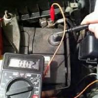 Simple tips on how to test a transformer with a multimeter for operability
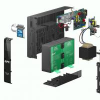 Repair of uninterruptible power supplies Commercial proposal for the repair of an uninterruptible power supply
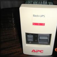 Do-it-yourself UPS repair: wizard's advice Repair of apc uninterruptible power supplies
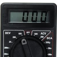 Repair of a multimeter m 830b does not show an ohmmeter
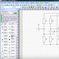 Programs for drawing electrical circuits
 Drawing boards in Sprint-Layout correctly from the first steps
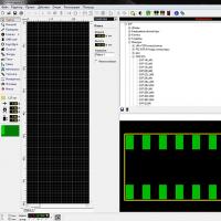 What program can open the file