Dps power supply. A tale of how I made a powerful laboratory power supply from RD DPS5020-C (Communication Version). Connection diagram and description
A homemade laboratory power supply was supposed to be easy to assemble, two-channel, with the ability to measure the indication of current strength, voltage and power. And it is desirable that it be powerful, very powerful! You never know how much ampere of current and hundreds of watts at the output will be needed in amateur radio practice)) Site Radio circuits already published full of self-made, but ready-made modules with Aliexpress such as DPS5015 + any switching power supply fits perfectly into this concept. Just by the way, I came across a faulty 400W pulsed power supply with an output of 40 V and a maximum current at a load of 14 A. After a small repair, we bought 2 DPS5015 modules and an input surge protector - due to considerable interference created by a pulsed power supply.

The assembly of the device lasted 3 days and most of the time was spent designing the elements in the case and manufacturing the front panel. It is printed on photo paper and coated with spray varnish.

The biggest expenses were spent on 2 x DPS5015 - that's about 4000 rubles. You can find the cheapest offer using.
Technical parameters of DPS5015 modules
- Input voltage range: 6-60V
- Output voltage range: 0-50V
- Output current: 0-15 A
- Output wattage: 0-750W
- Module weight: about 220g
- Module size: 79x43x41 mm (LxWxH)
- Output voltage resolution: 0.01V
- Output current resolution: 0.01 A
- Voltage measurement accuracy: ± (0.5% + 1 digit)
- Current accuracy: ± (0.5% + 2 digits)


Everything works fine in the end. The only drawback is one power source. It will not be possible to close the plus of the first and minus of the second channel for the total mass in order to obtain the voltage negative and positive with respect to the mass, as is required, for example, in the power supplies of amplifiers.


Another drawback is that the pulsation of the variable component at the output has a relatively large amplitude. Here is a 360 W load test at 15 A.

It was decided to put a 2x300 μH choke and a 220 μF capacitor at the output, which significantly improved the purity of the output voltage. The second version of such a power supply unit is described
The modules designated by the Chinese manufacturers as DP50V5A, DP30V5A, DPS3003, DPS3005, DPS3012 and DPS5015 are ready-made DC / DC voltage converter blocks, programmable and designed to create powerful power supplies. The modules are Step-Down controlled converters. Most of them are monoblock, and only in versions with an output current of 12 and 15 amperes, the power section is assigned from the control on two flexible stubs. The cost on the Aliexpress website, depending on the model, is 2000-3000 rubles.
General information about DP and DPS DC-DC converters
Handles constant voltage and constant current, programmable power supply control. The voltage range is adjustable 0-50 V, step 0.01 V. The output current is adjustable in the range 0-15A, step 0.01 A. The module saves 10 groups of the set value when the power is turned off. Compared with traditional analog power supplies, it is more convenient, you can quickly set the desired voltage or current level.

The LCD of the module has the function of digital voltmeter and ammeter. You can view the target voltage, input voltage, output voltage, target current, output current, output power, etc. It also adjusts the brightness of the LCD screen.


DP and DPS modules have many advantages: small size, extended functions, good visual display, high reliability, accuracy, the unit is used independently, can be built into the desired device.
Main technical parameters
- input voltage range: 6-60V
- output voltage range: 0-50V
- output current: 0-15 A
- output power: 0-750W
- product weight: about 220 g
- module size: 79 * 43 * 41 (mm) (L * W * H)
- output voltage with resolution: 0.01V
- output current measures with resolution: 0.01 A
- output voltage accuracy: ± (0.5% + 1 digit)
- output current with accuracy: ± (0.5% + 2 digits)
Module table DP50V5A, DP30V5A, DPS3003, DPS3005, DPS3005-C, DPS5005, DPS5005-C, DPS3012, DPS5015, DPH3

Old versions - table in English

Power is supplied to them from pulsed power supplies of suitable power.

Please note: the input voltage must be at least 1.1 times higher than the output voltage. When the current is more than 10 A or the temperature exceeds 45C, the fan will start working. When overheating more than 65C, the module will be automatically turned off.
Connection diagram and description

- IN +: positive voltage input
- IN-: negative input
- OUT +: output positive
- OUT-: output negative
DC input voltage range of 6-60V and 60V is the limit that must not be exceeded, otherwise the unit will be burned. And do not try to supply AC 220 V to the input, otherwise there will be a big fireworks!

Controls - Button Functions

- 1-set voltage / scroll up / extract M1 data group
- 2-set data / retrieve specified group data / save to specified group data
- 3-set current / scroll down / extract M2 data group
- 4-1.44 ″ color LCD screen
- 5-potentiometer / data adjustment / lock all buttons
- 6-Turn on or off
Display indications

- 7- the set value of the output voltage
- 8- the actual value of the output voltage
- 9- actual value of the output current
- 10- actual value of output power
- 11- actual value of input voltage
- 12- set value of the output current
- 13- lock or unlock row
- 14- confirm or save
- 15- current or voltage status
- 16- setting memory data
- 17- turn on-turn off
- 18- setting the output voltage
- 19- setting the output current
- 20- setting overvoltage protection
- 21- setting overcurrent
- 22- setting power overload
- 23- setting screen brightness
- 24- setting a dataset in memory
- 25- the actual value of the output voltage and current
User manual
When the power supply is connected, the screen shows the welcome splash screen and then goes to the main interface. In the main interface, voltage and output current values, you can set the current value - located at the top of the screen. On the left side are the current real output voltage, real output current and real output power. Input voltage data is located at the bottom of the screen.
Setting protection
Push the pages up or down to the page to show S-OVP, S-OCP or S-OPP, this is the setting of the overvoltage, overcurrent and overpower values, respectively; short press the coding on the potentiometer to enter the adjustment status of the numerical value you want to adjust. Turn the encoder of the potentiometer to adjust the numerical value. If you want to exit the adjustment - short press SET.
Adjusting the brightness of the screen
Scroll the pages up or down to the page marked B-LED, and then briefly press the potentiometer encoder to enter the screen brightness adjustment state. Turn the potentiometer knob to adjust the numerical value. To exit the adjustment menu - short press SET. There are 6 levels of LCD brightness, with 0 being the darkest and 5 being the brightest.
How to program memory
There is also a changeable ON / OFF parameter near the cell. It works as follows: if, when the converter output is activated, call the data from the memory cell with the ON value - the parameters will be applied immediately, the output will remain active, if OFF - the output will turn off. When the output is deactivated, there is no difference. The new version of the converter has an additional menu item where you can set and enable / disable the output of the converter when recalling data from a memory cell. To quickly recall data in cells M1 and M2 - you must press the corresponding button on the left. Writing to other memory cells is the same. Select a cell, make changes, save by pressing SET - the cell number lights up under the CV icon.

Hello electronics lovers! This story began with the purchase of a similar module - DPS5015, or rather, with how it burned out for me. I described all the twists and turns of the repair associated with it in this. And so much I liked this Chinese man in communication, that when a new, more powerful version came out, and even with communication (although I did not have an urgent need for increased power), I thought: let the guy work - and ordered the most powerful one, at the moment, from their line, the block is DPS5020-C (especially since I already had a kilowatt power supply for it). And I decided to take it with full communication capabilities - both with USB and with Bluetooth modules.
Warning: There will be a lot of pictures and text next. Whom it does not scare you - welcome under the cat.
I had this power supply. (Although it is recommended that there be a stock). I actually ordered 800W (because it was taken for 750W DPS5015), but the seller said that he would send me 1000W instead of him for the same money, and, of course, I agreed, and even rejoiced for a while that I received a kilowatt power supply at a rather attractive price - $ 59.33. But I was not happy for very long - this unit also went through one adventure with me - a capacitor exploded inside it with shooting, and for no apparent reason - when I was just feeding it to the DPS5015 after repair and revision, and even with a low power consumption - about 20W. 
The explosion site is clearly visible (the capacitor is located separately, circled in red). Fortunately, the DPS5015 survived, and in the power supply itself, surprisingly, almost everything remained intact - in addition to the conductor, another 18V zener diode 1N4746A was knocked out further down the power supply, and of course, the fuse. Thank God, there is an inscription on the conder of its capacity - 223J, i.e. 22nF. I don't know what voltage is there, but apparently the Chinese were saving, so I set the maximum voltage that I found - 1.6 kV - now, I think, under no circumstances will it fly out. 
And the Chinese, as it turned out, saved on output electrolytes - they put 2 pieces, although the place is under 3, and even at 50V. And on this block I wind up the maximum of its capabilities - 55V, so that you can get 50V springs from the regulator. As a result, the weekend electrolytes, so that they would not be offended by me, had to be replaced with, well, and put them in 3, since there are 3 regular places. Well, on the recommendation, I added 2 ceramic 220nF capacitors to each one to smooth out high-frequency ripples. 
Now for block DPS5020. I have not yet met his description on Muska, so I will describe it in more detail. It came in standard foam packaging, so it got there well. Consists of 2 modules - power and control, connected to each other through 2 loops.
Photo of the English part of the instruction


Plus, there were also contact terminals and a gift pair of crocodiles inside.

This converter differs from previous models only in the output current of 20A, therefore, all operating modes and settings are exactly the same as those of the younger models. Therefore, I will not dwell on these descriptions, tk. detailed reviews on Muska have already been done several times. And I will dwell on the differences that have not yet been reviewed, namely, the presence of communication modules - USB and Bluetooth. Unfortunately, only one plug-in wire came in the package. Why "Unfortunately? It seems like you can only connect one communication module at a time and one wire should be enough. But I decided to connect both at once, so as not to pull out, so the wires need 2. But my regret was not long, tk. a long time ago I bought a bunch of such wires. And even their colors coincided. By the way, about the colors - pay attention - it does not fit into the usual logic at all. If you look closely, you can see that:
- Ground - red
- Rx - black
- Tx - yellow
- Vcc - green

Although now I would probably take it with side taps, such as SK-22D07:

I connected it according to the following simple scheme:

The rest of the wires are paralleled. Of course, it would be possible to connect the modules through diodes with pull-up resistors, but I didn't want to bother, so I made the switching hard, through a switch. The Bluetooth board, in my opinion, is unreasonably large, so I had to grind it a little,

to match the width of the USB module.

Then I decided to put them one on one, just on foamed 2-sided tape.


The USB module is smaller - so I put it on top:

The result is such a compact, elegant design. For her, I decided to press the button to the body - at the same time I solved the problem of how to reversibly press the button to the body. You can also take out the LEDs from them to the case in order to see which unit is connected, but again, I didn't want to bother. Soldered all the wires to the button:

Yes, and I started thinking how to place all 3 units together (S-1000-48 power supply, power supply and DPS5020 control unit) together. At first I thought of screwing the power unit on top of the S-1000-48, but then, looking again inside the S-1000-48, I found that the DPS5020 power module fits inside this unit, exactly between the cooler and the transformer, only upside down - screwed to the lid.

And the length of the harnesses and the connecting wire is just enough to get out, although I had to cut one rib in the ventilation grill of the S-1000-48 unit in order to pass both loops through it. And by the way, since the DPS5020 power unit is located in front of the cooler of the S-1000-48 unit, its own fan can, and even need to be removed. now there is no need for it and it will only interfere with the flow of the large fan. After that, the laboratory scientist matured, so to speak, into a finished design. It remains for him to make a box that would fit on the end of the S-1000-48 power supply unit. Then it's a matter of technology: a little 3D modeling, then a little 3D printer work - and here it is a finished box:

And then we begin to systematically fill it with filling. First, place the button:

Then we clamp it on top with a sandwich of switching modules:

We fasten the power one. Well, I decided to make one more conclusion directly from the S-1000-48 block directly, in case I suddenly need 55V through such. And finally, the power button and the DPS5020 control module:

Forgive me for the "dirt" on the wires - I tried to paint the silicone wire with a marker to color-code it. As you can see, silicone is very poorly painted.
Yes, since the 220V contacts are located on the same end of the S-1000-48 block, in order to bring out the 220V wire in a human way - from the back (and not like the last time -), I had to pass it under the main board of the S-1000-48 block , and at the end, so that it does not fray and does not break - I passed it through a piece of porous foam rubber and jammed the wire behind it.

The power wires, since it is supposed to pass currents of 20A through them, had to be taken quite thick. In one case, I took a silicone AWG16 - yellow, and in the rest - a stranded copper wire with a diameter of about 2 mm.

Well, under the power wires, I also had to ream the power supply grille - top and bottom. Well, so that the grille does not scratch the insulation, I wrapped these wires with electrical tape, and at the same time improved the color marking. Well, and the loops, too, to prevent chafing, I wrapped them with Mylar tape, passing the commutation wire between the harnesses. In general, it turned out to be a rather compact design, as for a kilowatt-hour.

The laboratory worker started working right away. But during the power tests, one nuisance was discovered: at a power of more than 150W, colored artifacts begin to appear on the screen:

then the color palette is broken:

and in the end, as a rule, everything ends with a white screen with a freeze and a lack of response to control:
 .
.Sometimes I even watched the screen rotated 90 degrees:

ending also in violation of the color palette

and the same white screen with a freeze.
I wrote about this situation to the manufacturer. He unsubscribed that there is nothing wrong with that - it’s just, apparently, the loops from the control module go close to the electrolytic capacitors and induction is induced from them. Therefore, you need to either place the loops away from electrolytes, or shield them. And my loops just pass through those powerful 63V electrolytes of the S-1000-48 power supply. I had to screen it. I found a braid (stocking) from the cables and stuffed both trains into it. And just in case, the communication wire to the USB and Bluetooth modules was stuffed into a separate braid.

I soldered the braid to the grounding terminal of the power supply, then I had to wrap it with tape again - so as not to accidentally short something inside the S-1000-48 - and, lo and behold, this gave results: the screen stopped showing artifacts, and the control stopped hanging.
Now a few words about how to work through the communication ports. First you need to download their program for this. Naturally, we need the DPS5020_PC_Software (2017.07.12) .zip file. You need to run and install it. You may also need CH341SER drivers - they are also inside. The seller recommends first downloading and testing the program to see if it will start normally on your computer before ordering a block with communication. The prog requires the operating system Windows 7 or higher. When working through a USB module - everything is simple when connected via a micro-USB cable to a computer, a virtual COM port is installed in the system, and you need to specify it to the program and click Connect.
Working via Bluetooth requires a little more steps. Well, firstly, you need to have Bluetooth itself on your computer. And this is either in a laptop, or I bought myself a module. (Of course, Bluetooth is still available for tablets and smartphones, but the manufacturer has not yet written programs for them. Although one professor already has a program for them on a smartphone)
After turning it on, while searching for bluetooth, you should find a bluetooth device that contains something like DPS in its name.

Then you need to enter the code for pairing devices.

The default is 1234.

After that, 2 virtual COM ports are installed in the system: Outgoing and Incoming.


In the program, you need to specify the Outgoing COM port, as a rule, the top one and click Connect.
After successfully establishing a connection, the program will block the control of the buttons, and all control will be carried out through the program.

In the main menu, i.e. In the Basic function tab, there are 2 virtual knobs for adjusting the output current and voltage. Adjustments can also be made by entering values into the boxes at the bottom of the handles. The graphs display the current value of voltage and current over time.

The Advanced function tab provides advanced configuration and management options.

The Data group operation area allows you to read data from 10 memory cells of the transmitter, change them and write them back to memory.
The Auto test area allows you to automatically change the voltage and current at the output with a specified delay. Unfortunately, only 10 steps are available after that the output is disabled.
The Voltage scan area allows you to automatically change the output voltage with a specified step and time interval. At the end, it turns off the output.
The Current area does the same thing, just the opposite: it changes the output current with a specified step and delay, and then turns off the output. (The top line is not just Output, but Output voltage (V) - it just didn't fit because of the enlarged font)
All time intervals can be a maximum of 60 seconds, more precisely 59.9 seconds.

Important! Since, after establishing communication between the converter and the computer, the control keyboard on the DPS5020 itself is blocked, then before closing the program, you must press the button Disconnect otherwise the inverter will remain in a locked state, which cannot be removed without reconnecting the program or restarting the inverter.
Well. and since it is considered a good form here to give also oscillograms of the noise produced by such modules, I will also try to do this. Unfortunately, of all oscilloscopes, only DSO138 showed a more or less adequate picture. Well, although he is crap, he will show an approximate picture of what is happening. So, let's begin: 
Oscillogram directly from the S-1000-48 unit itself, no load. 
Oscillogram from the S-1000-48 unit, with a load of 250W. It can be seen that the frequency and amplitude of the impulse noise have increased. 
Oscillogram from the DPS5020 unit, with the output not turned on. It can be seen that the impulse noise still creeps through. 
Oscillogram from the DPS5020 unit, with the output on and 50V sprung, but no load (load - oscilloscope) 
Oscillogram from the DPS5020 unit with a load of 7V and 0.7A. 
Oscillogram from the DPS5020 unit with a load of 20V and 2A. 
Oscillogram from the DPS5020 unit with a load of 40V and 4.13A.
Well, the final oscillogram at the maximum power that I can select for now - 250W: 
50V and 5A.
Conclusion.
DPS5020-C pros:- Availability of 2 communication options: USB and Bluetooth
- Nice design.
- Convenient display of information
- Compact circuitry, as for such capacities.
- The ability to charge batteries directly ( Attention do not mix polarity!)
- Very sociable and helpful salesperson-manufacturer.
- Only 1 communication wire is included in the kit (it was written off with the manufacturer - they do not plan to add a wire).
- Excessive size of the Bluetooth module (written off with the manufacturer - they are not planning to change it).
- Closed software, although here you can understand the manufacturer, and the people are already breaking it.
- In the presence of Bluetooth, there are no applications for smartphones and tablets, although, perhaps, they will still write. Cm. Update
- Ripple leakage even when outlet is closed.
Addition: (as I expected) The manufacturer contacted me and wrote that if I or my friends have the opportunity to create applications on a smartphone, then he can provide his products for free for research. Manufacturer .
Update
It is finished! Recently, the manufacturer has posted a mobile application that supports Bluetooth communication of android devices (Android 5.0 and higher is required) with such converters (of course, only a communication version).
So, if you have a communication version with a Bluetooth module (if there is no Bluetooth board, you can order it separately.) Download the mobile application,
Pros of S-1000-48:
- Acceptable price.
- The presence of a Russian warehouse.
- Tenacious.
- Parts applied without stock
- Quite large ripples
- The fan is quite noisy and is permanently on
- The seller freezes in case of problems.
In general, by combining these blocks, in fact, I got a kilowatt laboratory laboratory of a compact form factor at a price of a little over a hundred bucks.
A 3D model of the front panel on thingiverse.
I plan to buy +44 Add to favourites I liked the review +75 +134Hello electronics lovers! This story began with the purchase of a similar module - DPS5015, or rather, with how it burned out for me. I described all the twists and turns of the repair associated with it in this. And so much I liked this Chinese man in communication, that when a new, more powerful version came out, and even with communication (although I did not have an urgent need for increased power), I thought: let the guy work - and ordered the most powerful one, at the moment, from their line, the block is DPS5020-C (especially since I already had a kilowatt power supply for it). And I decided to take it with full communication capabilities - both with USB and with Bluetooth modules.
Warning: There will be a lot of pictures and text next. Whom it does not scare you - welcome under the cat.
I had this power supply. (Although it is recommended that there be a stock). I actually ordered 800W (because it was taken for 750W DPS5015), but the seller said that he would send me 1000W instead of him for the same money, and, of course, I agreed, and even rejoiced for a while that I received a kilowatt power supply at a rather attractive price - $ 59.33. But I was not happy for very long - this unit also went through one adventure with me - a capacitor exploded inside it with shooting, and for no apparent reason - when I was just feeding it to the DPS5015 after repair and revision, and even with a low power consumption - about 20W. 
The explosion site is clearly visible (the capacitor is located separately, circled in red). Fortunately, the DPS5015 survived, and in the power supply itself, surprisingly, almost everything remained intact - in addition to the conductor, another 18V zener diode 1N4746A was knocked out further down the power supply, and of course, the fuse. Thank God, there is an inscription on the conder of its capacity - 223J, i.e. 22nF. I don't know what voltage is there, but apparently the Chinese were saving, so I set the maximum voltage that I found - 1.6 kV - now, I think, under no circumstances will it fly out. 
And the Chinese, as it turned out, saved on output electrolytes - they put 2 pieces, although the place is under 3, and even at 50V. And on this block I wind up the maximum of its capabilities - 55V, so that you can get 50V springs from the regulator. As a result, the weekend electrolytes, so that they would not be offended by me, had to be replaced with, well, and put them in 3, since there are 3 regular places. Well, on the recommendation, I added 2 ceramic 220nF capacitors to each one to smooth out high-frequency ripples. 
Now for block DPS5020. I have not yet met his description on Muska, so I will describe it in more detail. It came in standard foam packaging, so it got there well. Consists of 2 modules - power and control, connected to each other through 2 harnesses.
Photo of the English part of the instruction


Plus, there were also contact terminals and a gift pair of crocodiles inside.

This converter differs from previous models only in the output current of 20A, therefore, all operating modes and settings are exactly the same as those of the younger models. Therefore, I will not dwell on these descriptions, tk. detailed reviews on Muska have already been done several times. And I will dwell on the differences that have not yet been reviewed, namely, the presence of communication modules - USB and Bluetooth. Unfortunately, only one plug-in wire came in the package. Why "Unfortunately? It seems like you can only connect one communication module at a time and one wire should be enough. But I decided to connect both at once, so as not to pull out, so the wires need 2. But my regret was not long, tk. a long time ago I bought a bunch of such wires. And even their colors coincided. By the way, about the colors - pay attention - it does not fit into the usual logic at all. If you look closely, you can see that:
- Ground - red
- Rx - black
- Tx - yellow
- Vcc - green

Although now I would probably take it with side taps, such as SK-22D07:

I connected it according to the following simple scheme:

The rest of the wires are paralleled. Of course, it would be possible to connect the modules through diodes with pull-up resistors, but I didn't want to bother, so I made the switching hard, through a switch. The Bluetooth board, in my opinion, is unreasonably large, so I had to grind it a little,

to match the width of the USB module.

Then I decided to put them one on one, just on foamed 2-sided tape.


The USB module is smaller - so I put it on top:

The result is such a compact, elegant design. For her, I decided to press the button to the body - at the same time I solved the problem of how to reversibly press the button to the body. You can also take out the LEDs from them to the case in order to see which unit is connected, but again, I didn't want to bother. Soldered all the wires to the button:

Yes, and I started thinking how to place all 3 units together (S-1000-48 power supply, power supply and DPS5020 control unit) together. At first I thought of screwing the power unit on top of the S-1000-48, but then, looking again inside the S-1000-48, I found that the DPS5020 power module fits inside this unit, exactly between the cooler and the transformer, only upside down - screwed to the lid.

And the length of the harnesses and the connecting wire is just enough to get out, though I had to cut one rib in the ventilation grille of the S-1000-48 unit in order to pass both harnesses through it. And by the way, since the DPS5020 power unit is located in front of the cooler of the S-1000-48 unit, its own fan can, and even need to be removed. now there is no need for it and it will only interfere with the flow of the large fan. After that, the laboratory scientist matured, so to speak, into a finished design. It remains for him to make a box that would fit on the end of the S-1000-48 power supply unit. Then it's a matter of technology: a little 3D modeling, then a little 3D printer work - and here it is a finished box:

And then we begin to systematically fill it with filling. First, place the button:

Then we clamp it on top with a sandwich of switching modules:

We fasten the power one. Well, I decided to make one more conclusion directly from the S-1000-48 block directly, in case I suddenly need 55V through such. And finally, the power button and the DPS5020 control module:

Forgive me for the "dirt" on the wires - I tried to paint the silicone wire with a marker to color-code it. As you can see, silicone is very poorly painted.
Yes, since the 220V contacts are located on the same end of the S-1000-48 block, in order to bring out the 220V wire in a human way - from the back (and not like the last time -), I had to pass it under the main board of the S-1000-48 block , and at the end, so that it does not fray and does not break - I passed it through a piece of porous foam rubber and jammed the wire behind it.

The power wires, since it is supposed to pass currents of 20A through them, had to be taken quite thick. In one case, I took a silicone AWG16 - yellow, and in the rest - a stranded copper wire with a diameter of about 2 mm.

Well, under the power wires, I also had to ream the power supply grille - top and bottom. Well, so that the grille does not scratch the insulation, I wrapped these wires with electrical tape, and at the same time improved the color marking. Well, and the harnesses, too, to prevent chafing, I wrapped them with Mylar tape, passing the commutation wire between the harnesses. In general, it turned out to be a rather compact design, as for a kilowatt-hour.

The laboratory worker started working right away. But during the power tests, one nuisance was discovered: at a power of more than 150W, colored artifacts begin to appear on the screen:

then the color palette is broken:

and in the end, as a rule, everything ends with a white screen with a freeze and a lack of response to control:
 .
.Sometimes I even watched the screen rotated 90 degrees:

ending also in violation of the color palette

and the same white screen with a freeze.
I wrote about this situation to the manufacturer. He unsubscribed that there is nothing wrong with that - it’s just, apparently, the loops from the control module go close to the electrolytic capacitors and induce noise from them. Therefore, you need to either place the straps away from electrolytes, or shield them. And my harnesses just pass through those powerful 63V electrolytes of the S-1000-48 power supply. I had to screen it. I found a braid (stocking) from the cables and stuffed both harnesses there. And just in case, the communication wire to the USB and Bluetooth modules was stuffed into a separate braid.

I soldered the braid to the grounding terminal of the power supply, then I had to wrap it with tape again - so as not to accidentally short something inside the S-1000-48 - and, lo and behold, this gave results: the screen stopped showing artifacts, and the control stopped hanging.
Now a few words about how to work through the communication ports. First you need to download their program for this. Naturally, we need the DPS5020_PC_Software (2017.07.12) .zip file. You need to run and install it. You may also need CH341SER drivers - they are also inside. The seller recommends first downloading and testing the program to see if it will start normally on your computer before ordering a block with communication. The prog requires the operating system Windows 7 or higher. When working through a USB module - everything is simple when connected via a micro-USB cable to a computer, a virtual COM port is installed in the system, and you need to specify it to the program and click Connect.
Working via Bluetooth is a bit tricky. Well, firstly, you need to have Bluetooth itself on your computer. And this is either in a laptop, or I bought myself a module. (Of course, Bluetooth is still available for tablets and smartphones, but the manufacturer has not yet written programs for them. Although one professor already has a program for them on a smartphone)
After turning it on, while searching for bluetooth, you should find a bluetooth device that contains something like DPS in its name.

Then you need to enter the code for pairing devices.

The default is 1234.

After that, 2 virtual COM ports are installed in the system: Outgoing and Incoming.


In the program, you need to specify the Outgoing COM port, as a rule, the top one and click Connect.
After successfully establishing a connection, the program will block the control of the buttons, and all control will be carried out through the program.

In the main menu, i.e. In the Basic function tab, there are 2 virtual knobs for adjusting the output current and voltage. Adjustments can also be made by entering values into the boxes at the bottom of the handles. The graphs display the current value of voltage and current over time.

The Advanced function tab provides advanced configuration and management options.

The Data group operation area allows you to read data from 10 memory cells of the transmitter, change them and write them back to memory.
The Auto test area allows you to automatically change the voltage and current at the output with a specified delay. Unfortunately, only 10 steps are available after that the output is disabled.
The Voltage scan area allows you to automatically change the output voltage with a specified step and time interval. At the end, it turns off the output.
The Current area does the same thing, just the opposite: it changes the output current with a specified step and delay, and then turns off the output. (The top line is not just Output, but Output voltage (V) - it just didn't fit because of the enlarged font)
All time intervals can be a maximum of 60 seconds, more precisely 59.9 seconds.

Important! Since, after establishing communication between the converter and the computer, the control keyboard on the DPS5020 itself is blocked, then before closing the program, you must press the button Disconnect otherwise the inverter will remain in a locked state, which cannot be removed without reconnecting the program or restarting the inverter.
Well. and since it is considered a good form here to give also oscillograms of the noise produced by such modules, I will also try to do this. Unfortunately, of all oscilloscopes, only DSO138 showed a more or less adequate picture. Well, although he is crap, he will show an approximate picture of what is happening. So, let's begin: 
Oscillogram directly from the S-1000-48 unit itself, no load. 
Oscillogram from the S-1000-48 unit, with a load of 250W. It can be seen that the frequency and amplitude of the impulse noise have increased. 
Oscillogram from the DPS5020 unit, with the output not turned on. It can be seen that the impulse noise still creeps through. 
Oscillogram from the DPS5020 unit, with the output on and 50V sprung, but no load (load - oscilloscope) 
Oscillogram from the DPS5020 unit with a load of 7V and 0.7A. 
Oscillogram from the DPS5020 unit with a load of 20V and 2A. 
Oscillogram from the DPS5020 unit with a load of 40V and 4.13A.
Well, the final oscillogram at the maximum power that I can select for now - 250W: 
50V and 5A.
Conclusion.
DPS5020-C pros:- Availability of 2 communication options: USB and Bluetooth
- Nice design.
- Convenient display of information
- Compact circuitry, as for such capacities.
- The ability to charge batteries directly ( Attention do not mix polarity!)
- Very sociable and helpful salesperson-manufacturer.
- Only 1 communication wire included.
- Oversized Bluetooth module.
- Closed software, although here you can understand the manufacturer, and the people are already breaking it.
- In the presence of Bluetooth, there are no applications for smartphones and tablets, although, perhaps, they will still write.
- Ripple leakage even when outlet is closed.
Addition: (as I expected) The manufacturer contacted me and wrote that if I or my friends have the opportunity to create applications on a smartphone, then he can provide his products for free for research.
Pros of S-1000-48:
- Acceptable price.
- The presence of a Russian warehouse.
- Tenacious.
- Parts applied without stock
- Quite large ripples
- The fan is quite noisy and is permanently on
- The seller freezes in case of problems.
In general, by combining these blocks, in fact, I got a kilowatt laboratory laboratory of a compact form factor at a price of a little over a hundred bucks.
I plan to buy +29 Add to favourites I liked the review +70 +115I greet everyone who looked at the light. The review will focus on, as you probably already guessed, a compact buck converter DPS8005 designed for the construction of a laboratory power supply. Distinctive features of this module are compact size, wide input voltage range, excellent measurement and parameter setting accuracy, as well as the presence of memory banks to save the current settings. The device is very interesting, so whoever is interested, you are welcome under cat.
RD official store on Aliexpress
General view and brief performance characteristics
- Packaging and equipment
- Appearance
- Dimensions
- Disassembly
- Management
- Computer connection
- Testing
- Efficiency calculation
- Links to other products
General view of the DPS8005 module:
Brief performance characteristics:
Manufacturer - Ruideng Technologies
- Model name - DPS8005
- Device type - step-down converter
- Case material - plastic
- Input voltage range - 10V-90V
- Output voltage range - 0.00V-80.00V
- Setting accuracy (resolution) of the output voltage - 0.01V
- Voltage measurement accuracy: ± 0.5% (2 digits)
- Output current - 0-5,100A
- Setting accuracy (resolution) of the output current - 0.001A
- Current measurement accuracy: ± 0.8% (3 digits)
- Output wattage - 0-408W
- Display - color 1.44 "
- Number of memory banks - 10
- PC connection - wired (USB) and wireless (BT)
- Dimensions - 79mm * 54mm * 43mm
- Weight - 150g
Equipment:
Step-Down module DPS8005
- wireless module with PC (BT)
- wired communication module with PC (USB)

The DPS8005 step-down module is supplied in a simple foam box, which significantly exceeds the dimensions of the module itself:

This is a big plus, since in case of blows or crumples, the chance of product safety increases markedly. In addition, inside the box there is a special liner made of foamed polyethylene, inside which there are details:

With such careful packaging, you don't have to worry about safety:

In addition to the modules themselves, the kit contains detailed instructions in English and Chinese:

I would like to note that when buying, you can choose any of three configuration options:
 |  |  |
I recommend taking a closer look at the maximum configuration, since it allows you to control the step-down module via a wireless Bluetooth connection. Saving a couple of dollars off the base (DPS8005 module only) isn't worth it.
Appearance:
The DPS8005 step-down module looks unobtrusive. There are only four control buttons, a regulator and a display on the front panel:

The plastic case of the module has protruding sides and stops for installation in various cases:

I would like to note that the assortment of the RD store (Ruideng Technologies) contains several DIY cases, so in some cases you can stop at them (links at the end of the review):

The arrangement of the elements is quite dense, there are no complaints about the installation (the soldering is good, the flux is washed off, the components are taken with a good margin). There is a 4-pin connector for connection:

Electronic components protrude somewhat outside the case, but this is not critical:

The wireless module is quite compact and will not take up much space in the future case:
 |  |
The work is based on the BK3231 controller (Bluetooth 2.1):

The wired communication module is the same size. The most popular microUSB connector is used for connection:

The work is based on the CH340G microcircuit - a USB to UART interface converter (USB-UART bridge). Unfortunately, you cannot connect two communication modules at the same time, since there is only one output in the DPS8005 step-down module. In addition, the connecting cable is also one:

Despite all this, I plan to make a switch for the choice of wired or wireless data transmission on the future power supply. I will probably talk about this in the second part.
Dimensions:
The dimensions of the DPS8005 step-down module are small, only 79mm * 54mm * 43mm:

By tradition, a comparison with a thousandth bill and a box of matches:

The weight of the module is almost 105g:

Disassembling the module:
If it is necessary to disassemble, it is necessary to bend four latches from the ends of the case and push out all the electronics:

The element base is as follows: power mosfet HY18P10, designed for 100V / 80A, dual Schottky diode VF40100C for 100V / 40A, current shunt, ring choke and electrolytes for 100V. The power mosfet is mounted through a thermal pad on a common radiator:

As you can see from the photo, all the electronics are mounted on three double-sided boards:

Dimensional elements brought out from the edge:

In the review, the board version is 1.1, the name of the module is DPS8005. The connection block for communication modules is not very well located, so you have to use a thin screwdriver in order to connect any communication module:

An encoder is used as a regulator:

Control:
On connection, everything is banal and simple - two inputs and two outputs:

For normal operation, a high-quality network power supply (PSU) is desirable, which is connected to the "IN +" and "IN-" sockets. Consumers are connected, respectively, to the jacks "OUT-" and "OUT +". If any communication module is available, then it must be connected to the corresponding connector (screwdriver for help). In the assortment of the store there are buck-boost modules with an additional board, where the connection is a little more complicated.
Most of these models have the same controls:

1) M1 button - setting the output voltage, moving up in the menu, a shortcut for preset groups M1
2) SET button - switching between the main menu and the settings menu. When the button is held down, the parameters are entered into memory
3) M2 button - setting the output current limitation, moving down in the menu, a shortcut for preset groups M2
4) multifunctional display - displaying information about the current parameters
5) encoder-button - setting the desired parameter value (more / less), scrolling through the menu, moving through the cells (registers) when pressed
6) ON / OFF - turn on / off the output voltage
Main (top) and additional (bottom) display menus:

Main menu items:
1.2) current preset volt / ampere
3,4,5) current readings of voltage, current and power
6) input voltage from external power supply
7) parameter setting lock indicator
8) "normal" mode icon
9) indication of the mode CV (voltage stabilization) or CC (current limitation)
10) memory bank indication (M0-M9)
11) indication of on / off output voltage
Additional presets menu items:
12) setting the output voltage
13) setting the output current
14) setting the limit voltage
15) setting the current limit
16) setting the power limit
17) setting the display brightness level (6 brightness levels)
18) indication of entering settings into the memory bank
19) current readings of voltage and current
All in all, the controls are quite simple. When connected to a computer, the buttons on the module are locked. Of the minuses, we can only note the not very good location of the power button, but basically everything is simple and convenient.
Computer connection:
To connect to a computer, you need to connect the required communication module (BT or USB) to the main DPS8005 module using a complete loop. In the case of a wired connection, it is necessary to connect the module to the USB connector of the computer using an interface USB -> microUSB cable (with interface DATA pins). After installing the drivers, a virtual COM port should appear in the system:


In this case, control from the module is blocked, the readings are transferred to the program:

The functionality of the program is good.
Testing:
To test and compare the results, I will use a simple stand made of an adjustable power supply unit Gophert CPS-3010 with crocodiles and a True-RMS UNI-T UT61E multimeter:

The minimum input voltage is 8.7V, with the declared 10V:

With a further decrease, the module is simply turned off. I do not currently have a power supply with a voltage higher than 32V, so I cannot measure the maximum operating voltage. In tests, the maximum will be 32V:

The ON / OFF button is very convenient, it allows you to disconnect the module output from the load:

Now let's check the error of the module by comparing the readings with a very accurate UT61E multimeter. When set to 1V output, the voltage was 1.0085V:

Let me remind you that the declared accuracy of the module is 0.5%, which at a voltage of 1.0085V is ± 0.005V. Unfortunately, the resolution of the module is two decimal places ("hundreds"), but it still fits into the error.

It fits into the declared accuracy. This model allows you to set hundredths of a volt, so for example, set 5.55V. As a result, we get 5.54V on the module and 5.548V on the multimeter:

When set to 20V, the picture is the same. On the device 19.99V, and on the multimeter 19.997V:

As I mentioned earlier, for the Step-Down module to work, a difference is required, which in this case is 1V. For my case, the maximum voltage at the output of the module is no more than 31V:

Next in line is the measurement of current readings. To do this, we will use the Juwei electronic load with a maximum consumption current of 3.5A. Let me remind you that the manufacturer claims the installation is up to thousandths of an ampere and an error of 0.8%. Let's start with low currents, for example, 0.05A:

As you can see, the readings diverge by one thousandth of an ampere, which fully corresponds to the declared parameters and even much more.
Let's raise the current with the load to half an ampere and as a result - again a discrepancy with the multimeter in one thousandth of an ampere:

Next, it measured at a more serious current of 2A:

The readings on the module are 2.001A, and on the multimeter - 2.002A. With a declared accuracy of 0.8%, the discrepancy can be ± 0.016A, while we have a discrepancy of 0.001A, which is just fine.
At 3A, the discrepancy was 0.003A, which is 8 times less than the declared error:

Since the maximum current for an electronic load is 3.5A, ordinary load resistors came into play. At a current greater than 5.1A, the module automatically switches to the current limiting mode, while the indicator changes from "CV" to "CC":

Similar behavior will be if you limit the output current to any value. This is a very useful function with which you can power LED lamps, charge batteries, so you should not neglect it.
At 5A at the output, the accuracy also corresponds to the declared one (discrepancy of 0.003A):

Since the power elements are installed with a large margin, there is practically no heating at a low output power of 40W (8V / 5A). Full power tests will probably be in the second part, since I do not have a high output power supply at the moment.
Ripple when powered by an adjustable power supply unit Gophert CPS-3010 at a load of 1A and 3.5A:

The ripple amplitude is small: at 1A up to 35mV (peak to peak 72mV) and up to 60mV (peak 120mV) at 3.5A.
Overall, the module showed good accuracy. I would like to have a voltmeter resolution of three decimal places, but alas, most likely this will be implemented in the following models.
Calculation of module efficiency:
Since this module is essentially a converter, there will always be losses during its operation. The calculation will be made at a small and maximum voltage for my stand at 10V and 32V.
The first in line is the option using a power supply with a high output voltage (32V):

Input voltage - 32V
- input current - 0.2A
- output voltage - 5V
- output current - 1A
Power P1 = 32 * 0.2 = 6.4W
Power P2 = 5 * 1 = 5W (in the future I will take according to the readings of the module)
Efficiency = P2 / P1 = 0.78, that is, 78% at ampere load.
Here it is necessary to take into account the error of the devices, as well as the losses in the connecting wires and terminals, because at a current of 1A they are rather big. Without taking into account losses, an average efficiency of 80-85% can be expected.

Input voltage - 32V
- input current - 0.55A
Power P1 = 32 * 0.55 = 17.6 W
Power P2 = 15W
Efficiency = P2 / P1 = 0.85, that is, 85% at a three-ampere load.
In theory, the higher the current, the higher the losses and the lower the overall efficiency of the converter.
Option with input voltage 10V and load 1A:

Input voltage - 10V
- input current - 0.57A
- output power (according to the module readings) - 5W
Power P1 = 10 * 0.57 = 5.7W
Power P2 = 5W
Efficiency = P2 / P1 = 0.87, that is, 87% at a load of 1A
Option with input voltage 10V and load 3A:

Input voltage - 10V
- input current - 1.68A
- output power (according to the module readings) - 15W
Power P1 = 10 * 1.68 = 16.8W
Power P2 = 15W
Efficiency = P2 / P1 = 0.89, that is, 89% with a three-ampere load.
Links to some other Ruideng Technologies products:

Light DIY case Total, the step-down module has shown itself to be on the good side. It is compact and easy to use. It can be used from any network adapter (for example, a laptop power supply), turning it into a full-fledged laboratory power supply. I plan to install this module in a computer power supply unit, slightly modifying it to increase the voltage. So far, out of the candidates, this one is:

What will come of this, see the second part ...
This module can be bought in the official store RD official store on Aliexpress
 Free satellite internet is it a myth or reality?
 How can I completely remove Mozilla Firefox from my computer?
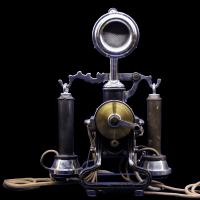 Who invented the telephone and in what year?
 Ways to find information on the web
 Construction of the Belomorkanal: history, terms, description
 White Sea-Baltic Canal
 Sending a request to call back (beggars) from Megaphone How to send I'm waiting for a call from a megaphone