A program for collecting electrical circuits. Programs for drawing electrical circuits. Paid programs for drawing electrical circuits
Drawing on paper is not a pleasure for everyone - it is long, not always beautiful, it is difficult to immediately calculate the dimensions correctly, and it is inconvenient to make adjustments. All these problems can be easily solved by a program for drawing circuits. Most modern software products contain a library with a set of basic elements. The required configuration is assembled from them, as from the constructor. Edits and corrections are made quickly, and different versions can be saved.
There are quite a few electrical circuit drawing programs that you can use for free. Partly these are demo versions with limited functionality, partly - full-fledged products. These functions are sufficient for designing an electrical wiring diagram in an apartment or house, but for professional use a product with broader functionality may be required. Paid options are more suitable for these purposes.
Like any software product, a diagram drawing program is rated for its usability. The interface should be simple, convenient, functional. Then even a person without special computer skills can easily figure it out. But, nevertheless, the main factor is the sufficiency of functions for creating circuits of varying complexity. After all, you can adapt even to an inconvenient interface, but it is more difficult to make up for the absence of some parts.
Simple program for drawing VISIO circuits
Many of us are familiar with Microsoft office products and Visio is one of the products. This graphics editor has a familiar interface for Microsoft products. The extensive libraries contain all the necessary element base, you can create schematic, wiring diagrams. It is easy to work in VISIO: in the library (window on the left) we find the required section, in it we look for the required element, drag it to the working field, put it in place. The sizes of the elements are standardized, they fit one with the other without problems.

Vision program for drawing diagrams - intuitive interface
What's nice is that you can create diagrams to scale, which will make it easier to calculate the required length of wires and cables. What is also good - not very much space is required on the computer's hard disk, even not very powerful machines will "pull" this program for drawing diagrams. I am also pleased with the presence of a large number of video lessons. So there will be no problems with mastering.
Clear ProfiCAD
If you need a simple program for designing electrical wiring, check out ProfiCAD. This product does not require downloading libraries like most others. There are about 700 built-in elements in the database, which are enough for the development of a power supply scheme for an apartment or a private house. The available elements are also sufficient for drawing up not too complex electrical circuit diagrams. If some element is missing, you can add it.
The main drawback of the program for drawing ProfiCAD diagrams is the lack of a Russian version. But, even if you are not strong in English, it is worth trying - everything is very simple. You will master everything in a couple of hours.

The principle of operation is simple: in the field on the left we find the desired element, drag it to the right place in the diagram, turn it to the required position. Moving on to the next item. After completing the work, you can get a specification indicating the number of wires and a list of elements, save the results in one of four formats.
Compass Electric
The program with more serious functionality is called Compass Electric. It is part of the Compass 3D software. In it, you can not only draw a circuit diagram, but also block diagrams and much more. As a result, you can get specifications, purchase lists, tables of connections.
To get started, you need to download and install not only the program, but also the library with the element base. Program, explanations, help - everything is Russified. So there will be no problems with the language.
When working, select the desired section of the library, graphic images appear in a pop-up window. In it, you select the necessary elements, drag them to the working area, placing them in the right place. As the scheme is being formed, information about the elements is included in the specification, where the name, type and denomination of all elements are recorded.
Elements can be numbered automatically or manually. The method is selected in the settings menu. You can change it in the process.
QElectroTech
Another program for drawing circuits QElectroTech. The interface resembles Microsoft products and is easy to use. There is no need to download the library to this program, the element base is "built-in". If something is not there, you can add your own elements.
The finished scheme can be saved in get format (for further work with it in the program) or as an image (jpg, png, svg, bmp formats). After saving, you can change the dimensions of the drawing, add a grid, frame.

QElectroTech - free editor for creating wiring diagrams
This program has disadvantages. First, the inscriptions can be done in only one font, that is, if you need a drawing according to GOST, you will have to somehow figure out how to change the font. Second, the sizes of frames and stamps are set in pixels, which is very inconvenient. All in all, if you need a circuit drawing program for home use, this is a great option. If you need to comply with the requirements of GOST, look for another.
123D Circuits Electronic Circuit Simulator
If you don't know how to draw a diagram on a computer, take a look at this product. 123D Circuits is an online service that allows you to create a simple circuit with the ability to create printed circuit boards. There is also a built-in simulator that simulates the operation of the finished circuit. The function of ordering a batch of finished boards (for a fee) is available.

Before starting work, you need to register, create your profile. Then you can start working. Multiple users can work on the same project using shared libraries. In the free version of the program, you can create an unlimited number of schemes, but they will be publicly available. In the hobbyist plan ($ 12), five schemes can be personal, and there is also a 5% discount on the manufacture of boards. The professional plan ($ 25) gives unlimited personal schemes and the same discount on ordering boards.
The diagram can be drawn from the existing components (there are not very many of them, but you can add your own) or imported from the Eagle program. Unlike other programs, the 123D Circuits library does not contain schematic designations of elements, but their mini-copies. Interface with two side margins. On the right, a section of the library with an element base is highlighted, on the left - a part of the settings and a list of used elements. After completing the work, the program itself forms a schematic diagram, and also suggests the location of the elements on the board (you can edit it).
Everything seems to be good, but 123D Circuits has serious flaws. First, the simulation results are often very different from real readings. Secondly, the functionality is small, it will not work to make a really complex scheme. Conclusion: This program is mainly suitable for students and beginner radio amateurs.
Paid programs for drawing electrical circuits
There are many paid graphic editors for creating diagrams, but not all of them are needed for "home" use or for work, but not directly related to design. Paying a lot of money for unnecessary features is not the smartest decision. In this section, we will collect those products that have received a lot of good reviews.
DipTrace - for PCB design
For experienced radio amateurs or those whose work is related to the design of radio engineering products, the DipTrace program will be useful. It was developed in Russia, therefore it is completely in Russian.
There is a very useful function in it - it can develop a printed circuit board according to a ready-made scheme, and it can be seen not only in two-dimensional, but also in a three-dimensional image with the location of all elements. It is possible to edit the position of elements on the board, develop and correct the device case. That is, it can be used to design wiring in an apartment or house, and to develop some kind of devices.

In addition to the program itself for drawing diagrams, you will also need to download a library with an element base. The peculiarity is that this can be done using a special application - Schematic DT.
The program interface for drawing diagrams and creating printed circuit boards DipTrace is user-friendly. The process of creating a diagram is standard - we drag the necessary elements from the library onto the field, unfold them in the required direction and put them in place. The element with which they are currently working is highlighted, which makes the work more comfortable.
As the scheme is created, the program automatically checks the correctness and permissibility of the connections, the coincidence of the dimensions, the observance of the clearances and distances. That is, all edits and adjustments are made immediately, at the stage of creation. The created circuit can be run on the built-in simulator, but it is not the most complicated one, therefore it is possible to test the product on any external simulators. It is possible to import a scheme to work in other applications or accept (export) an already created one for its further elaboration. So the program for drawing diagrams DipTrase is really a good choice.
If you need a printed circuit board, we find the corresponding function in the menu, if not, the circuit can be saved (it can be corrected) and / or printed. DipTrace schematic drawing software is paid (there are different tariffs), but there is a free 30-day version.
SPlan
Perhaps the most popular circuit drawing program is SPlan. It has a well thought out interface, extensive, well structured libraries. It is possible to add your own elements if they are not in the library. As a result, it is easy to work, the program is mastered in a few hours (if you have experience with such software).
The disadvantage is that there is no official Russified version, but you can find it partially translated by craftsmen (the help is still in English). There are also portable versions (SPlan Portable) that do not require installation.

One of the "lightest" versions - SPlan Portable
After downloading and installing the program, you need to configure it. This takes a few minutes, the settings are saved on subsequent launches. The creation of diagrams is standard - we find the required element in the window to the left of the working field, drag it into place. The elements can be numbered in automatic or manual mode (selected in the settings). What's nice is that you can easily change the scale - by scrolling the mouse wheel.
There is a paid (40 euros) and a free version. In free, saving (bad) and printing are disabled (you can get around by creating screenshots). In general, according to numerous reviews, it is a worthwhile product that is easy to work with.
Simulation software for radio circuits with visual
demonstration of the constructed circuit
in the form of a 3D finished device and graphs of transients.
Program for drawing up radio circuits.
It also includes the ability to lay out printed circuit boards.
and programming of PIC controllers.
The distribution kit includes a visual presentation.
54Mb


A program for creating electronic circuits.
Nice handy simulator of electronic circuits.
It is very easy to draw radio circuits in it - interface
organized in the simplest way.
A program for the compilation of electronic projects.
Before starting the simulation mode, do not forget in the menu
Simulate-> Edit Simulation Cmd in Transient Tab
specify the time for calculating Stop Time, for example 25m (25ms).
In simulation mode, a half-screen graph will open.
When we click with the cursor on the required wire on the circuit elements,
the graph will show the change in potential at this point
during a given calculation time. To see
the graph of the change in the current through the element of the device follows
just click with the cursor on the required element of the schemes.
54Mb download simulator LTspiceIV

program for tracing printed circuit boards
for digital electronics
password: mycad2000
copy the crack to the program directory
and run 10Mb
Tags: Software for designing modeling of schematic solutions is presented here. It is not difficult to deal with it. Radio engineering programs are useful for radio amateurs. And this is not surprising. We need this software for simulation modeling of radio engineering structures. These books contain the most interesting ideas of useful devices, giving every radio amateur the opportunity to choose what he needs from a great variety of solutions and designs on the a3144 hall sensor, tried and tested in practice.
Proposed solution
There are exercises at the end of each section. They show the schematic and the results obtained during the simulation, when to run the circuit. Students are encouraged to solve these problems in order to compare the answers received with those given in the book. The purpose of these exercises is not to learn wiring diagrams, but to practice working with the program. It is also a software for building circuit simulation.Intuitive user interface
- Layered hierarchy and support for multi-sheet boards allow you to quickly and efficiently develop complex schematic drawings.
- positioning
- The Arrange, List Positioning, and Automatic Component Arrangement features help you quickly and easily optimize component placement and board dimensions.
- Efficient tracing capabilities
- A modern meshless autorouter is capable of efficiently and quickly routing both complex multilayer boards with different types of components, as well as simple two-layer projects.
- Comprehensive project check
- Extensive design verification options at various stages of creation allow you to identify errors before sending the files to the manufacturer. Checking includes the following stages: automated check of new components in libraries, detecting possible signs of errors and minimizing the "human factor"; validation of schematic connections (ERC); check of gaps, dimensions and various signs of errors on the board (DRC); checking the integrity of the connections on the board; comparison with the original project.
Error correction method
Errors are displayed in the form of a list and displayed in the project, it is possible to correct them "on the fly" by restarting the check. They simplify their work. Here you can download radio programs for free. Ours has a special focus. Download radio programs for free directly from this page - just click on the link. In addition to electrical parameters, data on housings, pinout and markings are provided. When knowledge and practice are added to this framework, curiosity turns into curiosity, and radio amateurism becomes a wonderful activity that can not only entertain you in your leisure hours, but enrich you with experience that will help you in your work, no matter what profession you choose for yourself. In any professional activity, there are many similarities in approaches and ways of finding solutions. To master this means to master the profession. Many of the basic electrical devices of the program can be developed on the fly with a minimum of menus.During adjustment or repair of electrical equipment, electrical circuits can be checked directly or by grounding.
The direct test method is used when the beginning and end of the tested electrical circuit are located in close proximity to each other, and auxiliary circuits are not required.
The grounding method is designed to test those electrical circuits, in which the beginnings and ends are located at a considerable distance. Its use is accompanied by the use of auxiliary circuits, which are grounding conductors, screens and metal sheaths of cables and cores, specially laid conductors, etc.
For any method of checking the electrical circuit, devices are used, the principle of operation of which is similar to the principle of operation of the probe (Fig. 1, a).

Rice. 1. Scheme (a) and the symbol of the probe (b), an example of testing circuits (c) and typical errors during testing (d, e)
When the probe circuit is closed through the circuit under test, the arrow of the device P deflects in the same way as when terminals 1 and 2 are short-circuited. Resistor R serves to limit the current flowing through the meter. In the following figures, instead of the complete circuit of the probe, its symbol is used, shown in Fig. 1, b.
Let us consider, using an example of a fragment of an electric drive control circuit (Fig. 1, c), the procedure for checking electrical circuits. In any case, it is advisable to start the verification process from the power circuits, for example from point A.
Probe P is connected to points A and B, which allows you to check the circuit between them, and when you press the S2 button - the serviceability of the button and the correctness of the circuit between points A and B and, thus, confirm that the circuit between them is formed through the contact of the S2 button , and not through another element of the circuit. After that, the probe is connected to points B and L (pos. II in Fig. 1, c), combining the circuit check with checking the operability of the S3 button. The sequence of subsequent checks is shown in Fig. 1 at the corresponding probe positions.
When testing an electrical circuit with a probe, it is necessary to visually check the number of cores of cables and wires connected to the mounting points of the circuit. For example, at mounting point B at the terminal of the closing button S3, two jumper wires from button S2 and a wire to the contact of contactor K must be connected.
When checking circuits, special attention should be paid to observing polarity in DC circuits and phasing in periodic circuits.

Let's consider some of the most common mistakes made when checking electrical circuits. For example, circuit 1 - 2 (Fig. 1, d) is bridged by the contact of the relay K1, therefore, when the probe is connected to points 1 and 2, no open circuit is detected in the circuit of contacts K2, short circuit or the closure of contact K4. Therefore, to check the circuits connected to points 1 and 2, it is necessary to first open the contact of relay K1.
Another type of errors arising from the formation of false circuits through the resistance of the pn-junction of the semiconductor diode in the forward direction is illustrated in Fig. 1, e. When connecting the negative probe of the P probe to point 1, the device will give the same readings as when connecting another probe to point 2, as well as to points 3, 4. This will not happen if you change the polarity of the probe.
The considered examples showed the implementation of this technological transition in a direct way.

Rice. 2
The grounding test begins with the installation of a temporary jumper E2 with a button built into it on one of the ends of the E1 cable under test. Then, touching the probe probe P to the core, check the integrity of the auxiliary circuit: common conductor (in this case, "ground") - button 5 - core G - probe P probe - probe "plus" of probe P - common conductor.
If the probe shows a closed circuit, press and release the button 5. If the jumper is installed correctly, the P probe should change its readings.
After checking the installation of the E2 jumper, they begin to search for a grounded conductor at the second end of the cable, connecting the P probe alternately to the conductors, and monitor its readings. If the probe shows a closed circuit, consider the desired core found and, having switched the grounding jumper E2 to another core, proceed to search for it on the other end of the cable.
The reason for the most common errors when checking by the grounding method is the assignment of the same number to different electrical circuits and the formation of a false circuit when connecting the tested cores of a wire or cable to a grounding conductor.
To prevent such errors, after finding the next circuit, disconnect and reconnect the grounding conductor with the S button. If the probe responds to the disconnection of the grounding conductor, the circuit has been found correctly. Otherwise, it is necessary to find and eliminate the cause of the short circuit of the tested circuit with the grounding conductor.
With this article, I begin to cover one of the most interesting topics this is the topic of computer, they say, circuit simulation of circuits of various electronic devices.
In general, the term simulation of electronic circuits has many synonyms, this is emulation of electronic circuits, simulation of electronic circuits, etc. I will stick to the term "computer simulation" or simulation of circuits on a computer, it is not important.
So let's go.
Today, there are many computer programs that are designed primarily for the development of various electronic devices and in such programs there is one of the important functions - the emulation of electrical circuits.
I will list only the most famous of them:
LTSpice and many other programs.
Today I want to introduce you to a program from National Instruments - this is a Multisim circuit emulator.
The free Multisim program with a limit of 50 elements in the circuit can be downloaded from the manufacturer's website at the link https://lumen.ni.com/nicif/confirmation.xhtml, there you can also find a version for educational institutions, more advanced than the previous one. , but also has its own limitations https://lumen.ni.com/nicif/us/academicevalmultisim/content.xhtml
Let's start by examining the program interface.
The main functional panels of the program are shown in the following figure.

The component panel is of particular interest. The component panel provides access to the component base. When you click on any of the selected icons of circuit components, a window opens. Component selection... The required component is selected in the left part of the window.

The entire component database is divided into sections (passive elements, diodes, transistors, microcircuits, etc.), and sections into families (for example, for diodes, these are diodes themselves, zener diodes, LEDs, thyristors, etc.). I hope the idea is clear.

Also, in the component selection window, you can see the designation of the selected component, a description of its function, select the type of body.
Simulation of circuits in the Multisim program.
Now let's go directly to practice. Let's put together a simple circuit in Multisim and make it work!
I downloaded from the Internet a multivibrator circuit on two transistors, where LEDs are used as a load.


We can use measuring devices, for example, a virtual oscilloscope and see the signals at various points in the circuit.

We made sure that the circuit works, this is where I finish my acquaintance with the Multisim program, if you are interested in the topic of circuit modeling, write your questions in the comments, I will answer with pleasure.
And finally, by tradition, I present to you a detailed video on modeling circuits in the Multisim program.
If you have not yet subscribed to the new issues of the Internet magazine "Electron", then fill out the form at the bottom of the page and receive new issues by e-mail in PDF format.
MEASUREMENTS AND TESTS DETERMINING THE CONDITION OF CURRENT PARTS AND CONTACT CONNECTIONS OF ELECTRICAL EQUIPMENT
The condition of the live parts and their contact connections, in addition to visual inspection, is checked by measuring the DC resistance of the windings, individual contacts, live sections at their joints (busbars and busbars). In the presence of short-circuited turns, the measured DC resistance is, as a rule, less, and in the event of a break, poor connection or breakdown of contact connections, it exceeds the passport values or standardized values. Deviation of one of the measurements from the factory data is an indication that the defect is in the connection of the winding with the switch or in the soldering of the windings.
With poor adjustment of the contacts of the switches, the transition resistance to direct current of the power contacts increases significantly in comparison with the standard values and the difference in resistances in phases.
The condition of the grounding wires and the quality of their contact connections are determined by external examination and according to the results of special measurements carried out using grounding meters. The range of resistances that have to be measured is very large - from 10 + 5 (contact resistances) to 105 Ohms (resistances of relay windings, resistors). Consequently, the methods and equipment required for these works are varied.
The results of measurements of resistance to direct current are not the only criterion for the state of live parts. The quality of critical contact connections can be verified by special tests.
Checking the wiring diagrams includes primary (power) and secondary circuits (both internal and external) and requires special attention and a strict sequence of operations with the conditional marking of the checked areas in the electrical installation diagram. This check consists of external inspection, continuity of the circuits, determination of the polarity of the winding leads, measurement of the insulation resistance and its testing, monitoring the operation of the circuit from a temporary voltage source.
During an external examination, they check the conformity of the installation to the project, the condition of the contact connections, the observance of the distances between live and between live and grounded parts, the marking and coloring of buses, cables and their cores, wires, apparatus and equipment, the observance of the required phase sequence, the correct technological installation, etc. etc.
Further verification is carried out by dialing, which is performed using various auxiliary devices. The most widely used elementary device is a probe, consisting of a 3336 battery, a 3.5 V flashlight bulb, flexible copper insulated conductors and Crocodile clips (Fig. 23).
Figure 23 Probe schematic
Special devices (probes) UP-71 and PU-82 are produced, the semiconductor circuits of which allow you to check (ring out) circuits with resistance up to 10 Ohm and 10 kOhm.These probes signal the presence of voltage on the circuit elements that are touched by the probes of the devices. In addition, the PU-82 device has a built-in light bulb to illuminate the place where the probe is directed. Both devices are powered by 332 type cells.
To check external communications (power and control cables), handsets, telephone headsets, intercoms (PU-82), portable radio stations (for example, "Cactus") are used, with the help of which two people maintain constant communication with each other; the cable cores are called by the devices and devices indicated above. A dial-through with the help of handsets of cable cores, the ends of which are located in different rooms, is shown in Fig. 24. The conductors of the cable are disconnected from the terminal clamps. One wire from the telephone handsets is connected to the "Earth" (the metal sheath of the cable), and the other wire "probes" all the cores of the cable one by one until they hear a signal in the tube, check the marking of the cable cores through which the connection is established, and proceed to the search for the next core cable.
The need to check the polarity of the terminals may arise when checking the connection: current and voltage transformers (when meters, phase meters, power relays are connected to them), 
Fig. 24 Checking the marking of cable cores with "continuity"
1-6 marking of cable cores, MT - handsets, HL - 2.5 V light bulb.
GB - 3336 battery
electric motors with many terminals (multi-speed motors)
The polarity of the terminals of a three-phase machine (engine, generator) is determined according to the diagram shown in Fig. 25, pre-setting the conclusions of each of the windings with continuity. Since the windings of a three-phase machine are shifted in space by 120 el. deg, in relation to each other, then when connecting the "-) -" battery to the beginning of the first winding and "+" of the galvanometer alternately to the beginning of the second and third windings of the battery, the arrow of the galvanometer at the moment of closing the circuit should deviate to the left. 
Fig. 25 Circuit for checking the polarity of the windings of a three-phase electric motor
Measurement of the insulation resistance of a fully assembled circuit with all connected devices (relays, coils and contacts of contactors and electromagnets, clamps, wires and cables) is performed with respect to "ground" (cable sheaths, cases of panels, cabinets, boards). Using a megohmmeter, they check the insulation resistance of control circuits, metering, protection, signaling.
After that, the insulation is tested with increased power frequency voltage. The test voltage for the secondary circuits of protection, control, signaling and measurement circuits with all connected devices (circuit breakers, magnetic starters, contactors, relays, devices, etc.) is 1 kV, the duration of its application is 1 min. The source for it can be a special apparatus for testing the increased voltage of secondary circuits. In the absence of the necessary equipment, testing with an increased voltage of industrial frequency is carried out with a megohmmeter at 2500 V for I min.
After completing the above operations, the circuit can be supplied with operating voltage from a temporary source to check the interaction of all its elements, but first you need to check and configure all the devices included in this circuit.
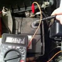 Simple tips on how to test a transformer with a multimeter for operability
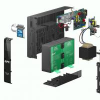 Repair of uninterruptible power supplies Commercial proposal for the repair of an uninterruptible power supply
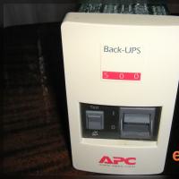 Do-it-yourself UPS repair: wizard's advice Repair of apc uninterruptible power supplies
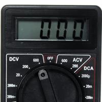 Repair of a multimeter m 830b does not show an ohmmeter
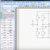 Programs for drawing electrical circuits
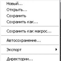 Drawing boards in Sprint-Layout correctly from the first steps
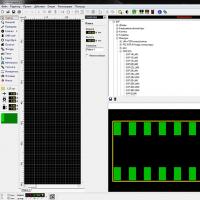 What program can open the file