Calculation of j antenna. Dual-band J-antenna for high-frequency KB bands. OQRS: QSL from the Internet
The publication is dedicated to the bright memory of the Avdeev radio amateur of Nicholas US5IMU who left us, which at one time kindly provided the author of these lines the material for the manufacture of this antenna.
IN lately Situation in the radio amateur market radio Stations Changed to the best, for us, radio amateurs, side. Today FM radio station on a 2-meter range has become available to everyone. In view of this, there is a question, what antenna to choose a radio amateur that first masters this interesting range? Answers can be heard a lot, but today we will focus on the omnidirectional pin antenna, the appearance of which resembles the English letter J. This is an antenna for a beginner, for the cottage, for local connections at VHF.
The physics of the work of this antenna will not consider in detail. Who wishes can familiarize yourself with her. We only note that the approval of the antenna with the transfer line is carried out with the help of a quarter-wave loop that is equivalent to the inductor inductance and capacity.
So, go to the practical part. The schematic view of the antenna is depicted in Figure 1.
Fig. 1. Conceptual image of j-antenna.
Using the formulas shown in Figure 1, or using the finished calculator in obtaining the dimensions of the antenna A, B, C and D.
For frequency 145.5 MHz:
A \u003d 148.29 (cm)
B \u003d 49.19 (cm)
C \u003d 4.63 (cm) (for the RFIDER \u003d 50 Ohm)
Material - copper or aluminum, tube or wire. What is at hand. I used the aluminum wire of the circular cross section with a diameter of 9 mm. The only one must remember the shortening coefficient K, which binds the electrical length of the antenna's web with its geometric length. The greater the thickness of the conductor, the greater this is the difference. In order not to guess the antenna length, it is recommended to make size B a little more, and then bite off excess during the setting.
The antenna setting was made on the KSV meter. In my case, the KSW meter RS-40 was used shown in Figure 2.

Fig. 2. The testimony of the KSV meter in the transmission mode.
The central cable core join the crocodiles to the long element (A), and the braid to the short (b). And we begin to turn on the transmission alternately, depending on the CWW meter and move the crocodiles, seeking the minimum of the CWW at the operating frequency. Included, looked at the CWW meter, turned off, moved crocodiles. In the area of \u200b\u200b4-6 centimeters from the jumper should be at least the CWS. If it fails to achieve a KSV close to 1.1-1.2, then you should play a length of B, biting several millimeters. During the measurements, the antenna is recommended to put between the two backs of the chairs, away from the floor surrounding objects, and all the more metal.
After setting up, clamping the cable to the bolts with the clamps, check if the setting was shot down, and then pour the contacts with a car or plumbing sealant.
After a few centimeters from the connection point, it is recommended to wind the filter, which is 4-5 turns of the same cable on the frame, for example, from 10 cubic syringe. This will slightly reduce the regimen of the RF currents on the cable braid and will reduce the possible interference TV.
Cable You can use any 50 ohm. In my case, this is a small piece of meter 3-4 thin RG-58U from the connection point of the antenna to the balcony, and then through the connector about 25 meters of Tolstoy RG-8. I note that the thicker the cable, as a rule, is less than its attenuation coefficient. The thinner - the loss of the useful signal is greater. With a cable length, a similar situation than the longer the cable from the antenna to the transceiver, the more the loss of the useful signal. In other words, to minimize losses in the cable we try to adhere to the rule "than the cable is thicker and shorter, the better."
The photo of my antenna is depicted in Figure 3. It costs for the second year already, survived all hurricanes, gust and icing.

Fig. 3. Appearance J-antenna on the mast 5 storey house. Photographed below.
Literature.
1. Karl Rothhamel: Antennas. Volume 2. Edition 11. Light Light Publishing House., 2007, p. 103.
Alexander US6igl
Exclusively for Radon magazine
VHF antenna with j-coordination
J-antenna (Fig. 1) has long been and is quite honorable among radio amateurs. Its design is simple, it is easily configured and consistent with the feeder of any resistance. However, large sizes (the total length is 0.75λ) makes it difficult to use the ranges. But in VHF bands, it is widely used. As can be seen from Fig. 1, it is a vibrator length λ / 2, taken from the end through matching devicecompleted in the form of a quarter-wave open line, closed at the bottom end.
The high input resistance of the half-wave vibrator when power from the end (several com) is easily transformed to the cable resistance by selecting the distance from the power point to the closed end of the line. Use as an open line transformer provides small losses at large transformation coefficients. The enhancement of the J-antenna is +0.25 dBD, i.e. Slightly exceeds the amplification of the dipole due to the emission of the two-wire line. The vertical J-antenna due to incomplete symmetry has a slight radiation with horizontal polarization (Fig. 1a).

We modify the J-antenna by moving the quarter-wave line by 90 degrees (Fig. 2).

Slightly adjusting the size, it is not difficult to get good matching and gain 0 dBD. However, this embodiment of the antenna already a noticeable part of the radiation has horizontal polarization (Fig. 2a). It causes a syphan current in a two-wire line that plays the role of a counterweight (current collector) in a j-antenna.

Add another half-wave vibrator by connecting it to the free end of the two-wire line (Fig.3).

The design is now completely symmetric in a vertical plane, the syphan current in the two-wire line is absent, as well as radiation with horizontal polarization (Fig. 3a).

This option is a collinear antenna of two half-wave vibrators with power through a quarter-wave closed on the end of the line. This antenna is described by SM0VPO (1) on its website in the article "6 DB COLLINEAR VHF ANTENNA by Harry Lythall - SM0VPO". Its reinforcement - (about 2.4 dBD) obtained due to the narrowing of the focus chart in the vertical plane. In the horizontal plane, the radiation diagram is circular. Antenna is structurally very simple and can be made from one piece of the rod or tube. To save its symmetry, the power cable is preferably connected through a symmetrizing transformer. SM0VPO uses a symmetrizing transformer as a U-knee, can be limited to several ferrite rings, dressed on the cable near the antenna power point. For brevity, call it Super-J antenna.

What further modification of this antenna is possible? By adding reflectors to it, we obtain the 2-element Super-J antenna (Fig. 4). This is an already directed collinear antenna. Her strengthening is +5.8 dBD.

By adding directors, we obtain the 3-element Super-J antenna (Fig. 5). Strengthening - +8 dBD.

An attempt to add the second director significantly increases the length of the antenna, but gives an increase in the strengthening of only 0.8 dB. What is the advantage of these antennas in front of Multi-element yagi? With an equal area, the gain coefficients are approximately equal, but the advantages of Super-J antennas are a small boom length and the associated small rotation radius, convenience of coordination. The disadvantages include the need to use dielectric mast, at least the upper part of it. Figure 6 shows the photos of the 3-element Super-J antenna on a 2-meter range made of an aluminum bar with a diameter of 8 mm.


Fig.6. General form 3-element antenna Superj.
The dielectric mast (for example, fiberglass) and the insulating spacer can be placed in the intervals between the elements (in Fig. 7, they are shown by more fat lines).

The power cable is better to dwell horizontally for reflectors and return to the mast a wide loop, away from the ends of the reflector. On the site near the antenna to the cable it is desirable to wear ferrite cores in 0.5 m.

Fig. 8 View of the 3-element Super-J Antenna on the mast
The design dimensions of the 3-element Super-J for the frequency of 145 MHz and 435 MHz are shown in Fig. 9 and in Table 1.

Dimensions are given in centimeters and between the conductors axes. The input resistance at the power point is 50 or 200 ohms. If the U-knee is used for symmetrization, it transforms the feeder resistance to 200 ohms, so the connection location to the two-wire line will be slightly further from the closed end. At the same time, the dimensions of the matching loop change slightly (see Table 1).
Table 1.
|
Frequency |
RMH, |
||||||||||
|
52,5 |
34,5 |
||||||||||
|
52,5 |
34,5 |
41,5 |
|||||||||
|
14,7 |
17,5 |
17,7 |
16,3 |
11,5 |
0,25 |
||||||
|
14,7 |
17,5 |
17,3 |
16,3 |
11,5 |
13,8 |
0,25 |
* - The size is specified when setting up.
D is the diameter of aluminum or copper conductors, from which an antenna is manufactured.
For convenience, the configuration, the matching device is recommended to perform with two "sliders" (mobile contacts): one, closing the two-wire line, is used to configure the resonance, the second feeder connecting to the minimum level of the CWS. This allows you to quickly configure the antenna, but after selecting the "crawls" positions, it is necessary to ensure reliable contact (soldering or bolts). The efficiency of the antenna is extremely dependent on the contact resistance. At the same time, to remember the inadmissibility of contacting copper-aluminum and the protection of contact from moisture. Requirements for contact resistance on the open end of the Jöriage, on the contrary, incredible, since the current is minimal there. An antenna for an average frequency of 145 MHz from an aluminum rod with a diameter of 8 mm was made. It was attached to a fiberglass tube with a diameter of 23 mm used as a mast. A ferrite tube was used as a symmetrous device, dressed on the cable near the antenna power point. At first, a single-element antenna Super-J (Fig.3) was checked. It was seen that when the antenna is located on a wooden table, in parallel with the ground and the adjustment is not coincided with the vertical arrangement. Therefore, the antenna setting must be carried out by setting it vertically. It is enough that the distance from the lower ends of the vibrators to the ground was about 0.5 m. Moving the closing jumper along the two-wire loop and moving the cable connectionpoints (these adjustments are interdependent) quite simply manages to match the antenna to the KSV<1,1 на желаемой частоте. полоса частот по уровню ксв<1,5 превышает 5 мгц. затем к мачте и активным вибраторам были прикреплены бумы, также выполненные из алюминиевого прутка диаметром 8 мм, поскольку не имелось под рукой диэлектрических трубок необходимой жесткости. в средней точке вибраторов напряжение близко к нулю, поэтому проводящий бум слабо влияет на характеристики антенны, что подтвердило предварительное моделирование. на бумах были установлены рефлекторы и директоры, длины которых выполнялись по расчету модели с помощью программы mmana. пассивные элементы резко снизили входное сопротивление антенны. однако слабо выраженный минимум ксв был найден. передвигая перемычку, и сдвигая точки подключения кабеля, нашли положение, когда минимум ксв соответствовал частоте 145 мгц и уровень ксв не превышал 1,2. длины вибраторов не регулировались. по сравнению с настройкой одноэлементной антенны настройка трехэлементной антенны значительно более острая и критичная. полоса по уровню ксв<1,5 составляла около 3 мгц. длина шлейфа оказалась несколько меньше, а расстояние от замкнутого конца шлейфа до точки питания кабелем с сопротивлением 50 ом несколько больше расчетных значений. работа антенны предварительно оценивалась в городских условиях (кругом были высокие здания, полностью закрывавшие горизонт) при расположении ее оси над землей на высоте всего 1,5 м. по сравнению с четвертьволновым автомобильным штырем она давала прирост сигнала на 2-3 балла при связях на расстояниях 10-50 км. направленность в горизонтальной плоскости была ярко выражена. общее впечатление - антенна работает. более аккуратные оценки работы антенны были сделаны на открытой местности в дачных условиях при подъеме антенны на мачту высотой 7 м. сравнивались антенна рис.6 и четырехэлементная антенна "квадрат" с вертикальной поляризацией (рис.10). антенны устанавливались на одной и той же стеклопластиковой мачте в одном и том же месте. использовался один и тот же кабель в качестве фидера и один и тот же трансивер. оценивалась работа по открытию и слышимости репитеров, расположенных на расстояниях от 30 до 100 км и оценкам корреспондентов при проведении qso в прямом канале на расстояниях до 70 км.

Fig.10. Antenna "4 square", with which the antenna Fig.6 was compared.
In most cases, the estimates were very close. If you heard the "square", they also heard SuperJ. The four-element "square" had a narrower pattern of the orphanage in the horizontal plane, so it had to more accurately direct on the correspondent to obtain a maximum assessment, Super-J was almost rotated. The overall impression - the antennas have approximately equal gain and good suppression of the rear petal. The test of the antenna is two times lighter than the "squares" and has a significantly smaller moment of rotation and sailboat. Fig.11-14 shows the elements of the antenna design.

Fig.11. Short-chain jumper, cable connection node and symmetrizing ferrite choke.

Fig.12. A knot for fastening the two-wire line to the mast.

Fig.13. Knot attaching booms to mast.

Fig.14. Knot fastening elements to booms.
In the application - files for modeling the described antennas: MMANA files
Ru3arj Vladislav Shcherbakov, [Email Protected]
Photos rw3acq Sergey Filippov, [Email Protected]
_________
(1) SM0VPO In its article, for some reason, the antenna increases with respect to some quarter-wave whip (apparently, the automotive antenna), from where it takes it 6 dB.
V. Markov
Radiocobbies 6/2003
Kv antennas
J-antenna, its scheme and design are described repeatedly in print. This antenna is mainly applied to VHF bands and on high-frequency kV bands. If you fulfill the coaxial cable coaxing cable, taking into account its shortening coefficient, it can be used on long-wave Kb bands. The diagram of such an antenna placed horizontally is shown in Fig. one.
For fastening the cable, wires and stretch marks, slats are used from insulating material, for example, from a textolite, 2-3 mm thick (Fig. 2).
The power cable connection location is 1/8 of the part (AA-B in Fig. 1) of the matching cable (loop), counting from the shortened end, for the 50-ohm cable and on 1/7 of the part - for the 75-ohm. Moreover, the consistent loop and the power cable of the same type. At the point in the braid on the end of the cable at a distance of 1 cm, the cable is wrapped on the outer insulation and the PVC isolant is wound. The length of the emitter L antenna is first calculated for the desired range, and then specified when setting up using a gir (Grid-Dip-Meter).

After the manufacture of antenna, all soldering and open parts of the braid are cooked with plasticine or sealant. The table is given an antenna dimensions for all KB ranges (the length of the loop is given for a cable with polyethylene insulation). The antenna canvas and the consigning loop should be on one straight line.
|
Range, M. |
Vibrator, |
Corresponding train, L, |
Distance A-b, m |
|
|
Cable 50 Ohm. |
Cable 75 0m. |
|||
For a range of 20 m and above, I recommend the vertical execution of the J-antenna. The author made several such antennas for 20 and 10-meter bands. And as a mast used telescopic fishing rods with a length of 6 and 7 meters, in which the uppermost section is removed. At the top of the fishing rods, the "asterisk" is strengthened, which serves as antenna capacitive load. It is made of 6 g-shaped, horizontally located long side of 30 cm, wires (bimetal, aluminum with a diameter of 2-3 mm). The vertical 5-centimeter parts of these wires are located evenly around the tops, are wrapped with a tinted copper wire and all are registered together. The outer ends of the horizontal conductors of the "asterisks" are served at a distance of 1 cm and are connected by a copper wire with a diameter of 1 mm, as shown in Fig.3.

The antenna canvas are made of a double copper wire 01 mm in general isolation of the "noodle" type with a distance between the wires 2-3 mm. Both wires at the end are cleaned at a distance of 1 cm, twisted and solder together, and then fall to the "asterisk". After that, "noodles" is wrapped around the fishing rod, not allowing its twisting.
For antenna to 20 meter band, the wire is first wrapped with a step 2 cm at a distance of 180 cm, then with a step of 4 cm at a distance of 80 cm, then with a step of 10 cm - 60 cm, and then the wire of 240 cm is simply placed along the rod. When winding every 50 cm, the wire is strengthened by PVC tape.
Then the fishing rod with the wound emitter put vertically to the ground (roof of the house), connect the gir to the steamed together as well as near the "asterisk" to the ends of the "noodles" and measure FPE3.
If the resonance is lower in frequency - the wire is shortened, if higher - extend, achieving FPE3 \u003d 14100 ... 14120 kHz. After lifting an antenna on the working height, the resonance practically does not "leave". Thus, on a fishing rod, a wire with an electrical length of X / 2 is wrapped up and an antenna is implemented as a shortened half-wave dipole.
Now connected to the antenna cannon, the agreement cable from the table with a tap for connecting the power cable. The fishing rod is attached to the mast at a distance of 20 ... 30 cm from the end and does not require stretch marks. The antenna at the antenna was 1.1 ... 1.2 per 14000 and 14350 kHz, and at 14120 - 1.05.
The advantages of J-antennas: broadband, simplicity of constructive performance, does not require counterbifts.
Disadvantage -Onodiapace.
For radio amateurs having LW with a length of 81-84 m, it can be recommended to coordinate it with coaxial loops with dimensions taken from the table. But before it should be verified using a guide or the impedance meter, which LW has the maximum input resistance on the required ranges, i.e. Its electrical length is multiple x / 2.
We offer a simple variant of the two-band Kb J-antenna, tested on the ranges of 21 and 28 MHz. The authors have long wanted to practically check this antenna in the work. Victor, UA6G, took over the development and execution of a mechanical structure, and Vladimir, UA6HGW, made the necessary calculations and configured the antenna.
In KB and VHF bands, various vertical pin antennas are widely used. More often, the quarter-wave vertical vibrators with systems of counterweight or "artificial earth" are used, thanks to which these antennas work, being, in principle, the analogues of the half-wave vibrator. Unfortunately, fulfill the high-quality system of "artificial earth" or counterweight is not so easy, and the poor-quality system sharply reduces the antenna efficiency as a whole. Nevertheless, Ground Plane type antennas use very popular with radio amateurs. At the same time, many pay attention only to the qualitative fulfillment of the fourth-wave radiator itself and, due to the lack of area, to accommodate a full-fledged grounding system, "often do not pay attention to the" Earth "using various surrogate systems of counterweight or grounding. It is necessary to make a reservation that in the VHF the range of such a problem practically does not exist, because The base of the antenna and the counterweight can be lifted at a sufficient height, which allows you to place a system designed to work even on the longest meter waves.
If the area for the placement of the antennas of other types is not enough, then for the high-frequency portion Kb of the range, it is better to use a vertical half-wave vibrator, powered from the bottom end and installed without stretch marks. To coordinate its high resistance with low feeder resistance, various matching devices are used - both resonant and broadband. One of the most famous and simple methods of matching is using a quarter-wave resistance transformer. And there are two ways to power with such a transformer - sequential and parallel.
With sequential nutrition A quarter-wave line is used, which can be made in the form of an air line either a line with a solid dielectric. More often use symmetric lines for this. The disadvantage of this method of nutrition is the need to install at the lower end of the insulator vibrator, which on KB bands causes structural difficulties and reduces the reliability of the structure.
With parallel nutrition The lower end of the transformer line, which is sometimes referred to as the loop, can be shred with a vibrator and ground, which is constructively more convenient, because allows you to abandon the use of a bulky supporting insulator. The feeder connection points in this case are chosen above, at a predetermined distance from the lower end of the line, which is then specified in the process of setting an antenna at a minimum of KSV. This somewhat makes it difficult to set up the antenna and narrows the operating frequency band, and also requires the use of additional measures to reduce the antenna feeder effect.
In both cases, the wave resistance of the line of the quarter-wave transformer must be correctly calculated and equally throughout its entire. The classic J-antenna is most often called this design. She has the length of the main vertical element - the emitter plus the line - is 3 / 4Lamda * to,
Where TO - shortening coefficient, depending on the configuration and transverse dimensions of these elements.
As the experience showed, these sizes may be different for different sections of the emitter and line.
The radio amateurs are most often used by J-antennas in the range of VHF and the high-frequency part of the Kb range, where their designs, having the necessary strength, are not too complex and cumbersome.

The main vertical element 1 (Fig. 1) is a grounded mast, which also serves as emitter, made of three steel pipes of different diameters connected by telescopic principle. The pipes of the links were precisely chosen in diameters so that they are tightly entered into each other. The length of the pipes was chosen with this calculation so that the end of one came to another to the distance sufficient so that the entire design of the antenna is firmly kept and did not swing without stretch marks. Therefore, the exact length of the entire vertical element assembly is difficult to indicate, but it, according to our calculations, was at least 12 m. The bottom pipe - the base of the antenna with a length of about 5 m and the outer diameter of 90 mm - was installed at the ground level on the concrete base inside the small room and went through a hole in a flat reinforced concrete roof 6, which is electrically connected to the ground circuit. After assembling the system in the nodes of the pipe connections was mounted using two screws with a diameter of 10 mm with nuts. The nuts were reliably welded to the outer surface at the end of the pipes in the plane perpendicular to the location of the matching elements 2. Screws 7 were screwed into the nuts, clamping the base of the pipe of the next link.
Elements 2 matching air lines are made of a steel pipe with a diameter of 0.5 inches for a range of 21 MHz and a galvanized bar with a diameter of about 8 mm for 28 MHz. Due to the fact that element 1 and elements 2 had to perform different diameters, some complexity caused the preliminary calculation of the sizes of emitters and air lines, because With this design, shortening coefficients to will be different not only for different ranges in accordance with the frequency, but also in connection with the change in the ratio of pipe diameters. For this reason, several different approximate practical formulas were selected for the calculation. They are shown in Table 1 together with the results of calculations.

In our opinion, in such cases, the distance D is better to indicate for the air gap between the elements 1 and 2, the smaller should not be done. The distance with pre-taking 0.03Lamda. Practice has shown that the exact value can be defined only after adjusting the specific antenna to the selected frequencies.
The initial calculation of the antenna was made to work in the telegraph range of 21 MHz. All sizes for the practical design of the design, we chose based on the compromise between real capabilities and calculations that could be corrected by checking using the MMANA-GAL program. To ensure reliable electrical contact from the upper end of the mast to the bottom, two copper conductors were laid from an antenna rope in the plane of the arrangement of the matching elements, which were additionally attached to each link using conventional flat chambers tied with screws with nuts. In order not to load Fig.1, only one of the cakes is conditionally shown on it. 3. On the tubes of matching lines, it is also desirable to secure additional copper conductors from an antenna rope or a single-core copper wire. When choosing such constructive solutions, the "tendency" of some citizens to the "hunt" for non-ferrous metal was taken into account, so most of the main elements were made of steel. It should be noted that when using heterogeneous metals, their corrosion may occur, and as a result - an increase in noise when taking. Therefore, it is desirable to use metals located in a galvanic row as close as possible to each other, or resort to additional measures (for example, to the maintenance of copper conductors, lead-tin solder and improved contacts with soldering). This also applies to small elements used in structures - to bolts, washers, nuts, etc.
Table 2 shows a part of the galvanic series of the most frequently used metals.

Another feature of the design is that the elements of the matching lines had to be made from the steel tube and the rod smaller diameter than the vibrator, i.e. Not as recommended in the literature. Therefore, the distance between the vibrator and the corresponding vertical elements 2 was chosen compromise and was somewhat less than the calculated obtained using the MMANA program. This caused some doubts about the possibility of obtaining good agreement with the power cable. There are still several important elements in the lines that are not shown in Figure 1, so as not to load it. These are plates set for strength and fixing the airbase between the vibrator and the matching lines. They should be performed from an insulating material with good insulating properties at high frequencies that do not lose them under the influence of humidity (for example, from a fiberglass or plexiglass, several pieces for element 2 of each range). Moreover, the lower plates can be combined directly with the homutics 5, and the upper set closer to the ends of the lines. Their position can be changed when setting up, fixing metal clamps on pipes with screws. Using the homutics 5, you can adjust the cable connection points, the central lived and the braid of which should be securely connected to them, best with soldering. To facilitate the configuration process, mobile clamps are also installed on matching links, with which you can pick up the full working length of the antenna vibrator and the length of the matching elements. After the final settings, it is desirable to connect with additional copper conductors 3.
Doubt caused a choice the best option for connecting the central cable and braid veins. In the literature it is difficult to find a specific answer, because There are various options, i.e. Connecting to matching items or to the main vibrator, which is more often used in the VHF range. Surprisingly, it practically turned out that in this case good agreement can be achieved, only by connecting the central core to elements 2, and the braid is to the vibrator 1.
The pre-configuration process of the antenna turned out to be difficult, but as a result, successful. The setting was carried out using the MFJ259 instrument. Then its results were adjusted according to the testimony of the CSW meter, with sufficient transmitter power, and finally - at full power in different parts of the ranges.
Since the antenna uses parallel food, all its disadvantages appeared. Two 50 ohm feeder cables 8 of the RK50-9-12 brand were laid inside the main mast, for which 4 holes of the required diameter had to do in it. This was not enough, and at the exit from the mast, the surplus cables had to be collapsed into two separate bays, which made it possible to reduce the antenna effect. Switching antenna from one range to another was made without any switches using connectors, which does not exclude the use of special coaxial switches, mechanical or coaxial relays.
The antenna was originally made and configured to the telegraph range of a range of 21 MHz. As practice has shown, it is first necessary to select the length of the vibrator A1 and the line B1, configuring them to the necessary resonant frequency using a moving hollow-jumper 4, which is fixed with nuts with nuts. It is best to do using the resonance indicator (gir) or an antenna analyzer (for example, MFJ259) if there are special additional elements to it, allow you to communicate the device with an antenna without connecting it. Then it is necessary to pre-select the distance C1 - i.e. The location of the cable is minimized at the selected frequency, adjusting it to the clamps 5, and adjust the setting more accurately, repeatedly repeating all of the specified adjustments.
After testing the antenna on this range, making sure that it is quite effective, we have added to it the alignment elements for the 28 MHz range and configured the system to this range in the same way. After you have configured the antenna for this range, I had to correctly adjust the matching by 21 MHz and then check the setting by 28 MHz. In the process of adjusting the adjustment on different ranges had to repeat several times. In practical work on the range of 28 MHz, we have also been repeatedly convinced of the high efficiency of the antenna, because At low power, it was possible to successfully carry out radio communications both with both neighbors and long-range correspondents.
Figure 2 and 3 shows the dependence of the CWF on the frequency obtained as a result of the settings for the ranges 21 and 28 MHz, and in Fig. 4 and 5 are the radiation charts obtained in accordance with the calculations for the optimal examples of the J-antenna according to the MMANA program.


It should be noted that the good work of the antenna probably contributed to the fact that there were no higher foreign objects near at a considerable distance, because Sometimes her good work even surprised that long-range correspondents were given higher signal estimates compared to stations working close to our settlement and using directional antennas and more powerful transmitters.
Such a design, in our opinion, can also be offered for other high-frequency KB bands, recalculating the antenna. Probably, you can add the upper link to it, designed to work at 144 MHz. Examples of similar combined J-antennas are in practice.
During the use of an antenna on the transceiver with a capacity of no more than 100 W, it was possible to carry out a large number of long-distance radio communications. This confirmed that it not only works effectively during transmission, but also provides good long-range reception. The design turned out to be durable and reliable - the antenna has been standing for more than 5 years and, despite the very complex, sharply changing meteo conditions in our region, and solved all the tests well.
The radio amateurs are widely used to work at the VHF half-wave antenna with resonator power. The coordination of the high input resistance of the half-wave emitter with a relatively low wave resistance of the coaxial cable is carried out using a quarter-wave resonator. The resonator has a high output resistance at its end, which depends on the design of the resonator, and the load at its end. Along the resonator, the resistance decreases according to the sinusoidal law, from the maximum at its end to zero at the bottom of the resonator. This allows you to use a coaxial cable of any wave resistance to power the half-wave antenna, which is connected to the end of the quarter-wave resonator.
The quarter-wave resonator, which ensures the coordination of the half-wave antenna with a coaxial cable is often performed from a two-wire line. Such a construction simplifies the design of the antenna and facilitates its adjustment. A half-wave antenna with resonator diet in his own way resembles the Latin letter "J". As a result, this antenna is often called "J-antenna" in various radio amatele literature.
It should be noted that the "j" antenna appeared in the world in the mid-twenties of the twentieth century. It was originally used to work on short waves. Approximately 50 years old, the J-antenna was still used in professional radio communications. Nowadays, this antenna is used only by radio amateurs. The radio amateurs developed many different designs "J" antennas that can be used both for field work and for stationary antennas. In this chapter, we will consider the most used by radio amateurs "J" antenna.
Simple J-Antenna
A simple J-antenna with a direct connection of the coaxial cable to the quarter-wave resonator is shown in Fig. 1. As is known, the classic j - antenna has the length of the radiating part "A" equal to L / 2. This part is a half-wave vibrator. The input resistance of the half-wave vibrator from any end of its end, and depending on the practical design of the emitter, can be about a thousand ohms in the 145 MHz band. To power the J-antenna, use the coaxial cable to connect to the part of the quarter-wave resonator "B".
Figure 1. J-antenna with direct connected coaxial cable to the quarter-wave resonator
This is the most common way to power the J-antenna. It is often used in constructing stationary J-antennas made of thick wire. At the end of the coaxial cable, a high-frequency throttle must be installed. This is necessary to prevent the radiation of the coaxial cable braid, and to eliminate the effect of the coaxial cable braid on the operation of the quarter-wave resonator. The high-frequency throttle for the 145 MHz range can be made in the form of a coax of a coaxial cable containing 10 -15 turns wound on the frame with a diameter of 20- 50 mm, as shown in Fig. 2. Currently, radio amateurs prefer to use 10-20 ferrite rings as a high-frequency choke, attached to a coaxial cable at a j-antenna point, as shown in Fig. 3. Magnetic permeability of these ferrite rings is non-critical.

Figure 2. Simple HF - choke

Figure 3. HF - ferrite rings based choke
Connecting a coaxial cable to an antenna during configuration can be quite simple to produce with "crocodiles", as shown in Fig. 4, and find the optimal point of connecting the coaxial cable.

Figure 4. Definition of coaxial cable connection points
But in fact, not everything is so simple! The radio amateurs that performed J - antennas know how much labor and time requires the determination of the connection point of the coaxial cable to the resonator. It seems that the antenna is already configured, and the shift point of the cable connection should lead to an improvement in the antenna CWV, and in practice the opposite happens!
Connecting a coaxial cable to a quarter-wave resonator is upset by the latter relative to its initial or calculated setting frequency. This reduces the effectiveness of the work "j" -antennas, leads to an increase in the CWS in the feed feeder. To eliminate this phenomenon, it is necessary to adjust the quarter-wave resonator in the resonance at the final stage of the antenna setting. In practice, it causes certain difficulties. As a result, often J -ANtenna has a CWW in the feed feeder within 1.5: 1, although, with a thorough adjustment of this antenna system, it is realistic to achieve a KSV in the power feeder of the antenna 1.1: 1.
At the end of J - antennas, even with a 0.5 watt radio station power, there will be high voltage sufficient to cause a burn, so it is necessary to take measures to prevent accidental touch to the end of the antenna. You can use j - antennas with a multiple L / 2, L, 1,5L, 2L. When experimental verification it turned out that the use of an antenna long? Increases the signal strength compared with a half-wave J-antenna by 1.5 dB, and when using an antenna with a length of 1,5L, the signal strength rose a little more than 2 dB compared to the half-wave antenna. In tab. 1 shows the length of the vibrator for the execution of the J- antenna L / 2, L, L, 1,5L, 2L.
Table 1. Vibrator lengths j - antennas Length L / 2, L, 1,5L, 2L
| L / 2. | L. | L (1.5) |
| 1050 mm | 2080 mm | 3120 mm |
J - antenna can work on the third harmonic, i.e. Antenna, configured to work in the 145 MHz range will operate on the range of 430 MHz. This makes it indispensable when working "Cross Band", for example, through repeaters or amateur satellite.
Directional J-Antenna
On the basis of the J-antennas, you can build directed antennas. In this case, the reflector and director are placed around the J-antenna, as shown in Fig. 5 At traditional distance for them. Depending on the length of the canvas of the active part J - antennas, you can use half-wave or wave reflector and director. Determination of the power points of the quarter-wave resonator for the directional J-antenna is similar to both for a simple J-antenna. At the end of the coaxial cable, it is necessary to use a high-frequency throttle.

Field J-Antenna with Combined Power
When using a portable radio station from remote places, the shortened antenna, which comes complete with a radio station, often not enough to work. In this case, together with the radio station, a half-life antenna will be successfully operating, which does not require "land" for its work and has an increase significantly more (up to 10 dB) compared with the short "rubber band". The field antenna, used in conjunction with the portable VHF of the radio station, should be easily installed, easily transferred, not to require additional configuration in the field of operation.
Such a j - antenna can be made of a plastic belt cable with a wave resistance of 450 ohms. The "Earth" of the quarter-wave resonator is soldered to the "land" of the antenna connector. Connecting the output of the transmitter with a resistance of 50 ohms to the quarter-wave resonator is made at a distance of 67 mm from the "Earth" of the connector. The non-working lived from the ribbon cable is pulled out, a hole is made at the top of the cable through which the fishing line is tied. With this line, the antenna can be stretched in space, suspended to the branch, to the eaves, etc. The scheme of the portable J - antenna from the ribbon cable is shown in Fig. 6. When carrying a J - antenna can be minimized, and simply hidden in his pocket.

Figure 6. Portable J - Antenna from a ribbon cable
J -ANtenna in the manufacture of it exactly does not require setup, and effectively operates in the VHF range of 145 MHz with low CWS. J - antenna can be connected to the transceiver through a coaxial cable with a wave resistance of 50 ohms. The transmitter communication with the quarter-wave resonator in this antenna is combined. It is carried out both through the magnetic field of the loop and through the connection to part of the resonator.
With its practical execution of the antenna, it is desirable to use a two-wire ribbon line with a wave resistance of 450 ohms. When using a line with another wave resistance, it is possible to change the connection point of the connection loop to the quarter-wave resonator. Currently, in specialized stores, two-wire transmission lines can be purchased with any standard wave resistance.
For the manufacture of J -ANtenna, you can use a self-made open line. In this case, the ratio between the distance relative to its conductor and the diameter of the wires components of the line should be 20 (Fig. 7). When using a homemade open line without plastic insulation, the length of the quarter-wave resonator should be 48 cm.

Figure 7. Two-wire transmission line
It should be noted when J -ANtenna is performed from a two-wire transmission line in plastic insulation, then the quarter-wave resonator must have a length L / 4, taking into account the shortening coefficient in the line, and the vibrator must have L / 2 (L, etc.) in free space . It is unacceptable to leave the second core cable free about the main web antenna, it should always be deleted. Otherwise, the efficiency of the antenna will decrease. It is possible a parallel connection of the conductor of the J-antenna line to perform the vibrator as shown in Fig. 8. In this case, the bandwidth of the antenna will expand slightly. This will simplify the antenna setting.

Figure 8. Parallel j-antenna line conductors
A ribbon cable-based j-antenna is one of the easiest in performance and operation. This antenna will allow radio amateur radio amateurs from alternative QTH when using portable radio stations.
Ribbon J - Antennas
Me was performed experimental J -ANtenna from aluminum foil used for food. This antenna showed itself efficient in operation and simple in the setup. This allows you to recommend to repeat the design of the ribbon J - antenna. The following paragraph will be devoted to the description of the ribbon J - antenna.
Ribbon J -ANtenna was made in size shown in Fig. 9. On a wide foil intended for cooking, a sticky tape type "Scotch" was pasted in advance. Then, with the help of scissors, an antenna was cut according to the dimensions shown in Fig. 9. After that, the antenna canvas was once again strengthened with a tape type "Scotch".

Figure 9. Ribbon J - Antenna
The section "A" of this antenna, a length of equal to 1 meter, is an antenna emitter. The quarter-wave resonator, made on the "B" section, was originally taken with a resonant frequency a little more necessary. This was done in order to subsequently be able to adjust it with a capacitive plate. Part "C", an equal length of 1 meter, represents the "land" of ribbon J - antennas. Although, theoretically, J - antenna may well work without part "C", therefore, without "land", but its presence improves the operation of the antenna. Changing the length of the "C" part during the setting allows you to adjust the value of the KSW in the short limits and ultimately reach the small value of the KSW in the antenna power feeder.
As is known, to accurately perform the parts of the antenna "A", "in", "C", their shortening coefficient must be known. In all books on the antennas that have been with me, the coefficient of shortening the antenna conductors was given only for a cylindrical conductor. The belt antenna is a flat antenna, therefore it is not applicable to the shortening coefficient for cylindrical antennas. The coefficient shortening the antenna conductors from the location of the antenna, from the influence of foreign conductive subjects on it. I received a coefficient of shortening antenna initially equal to 1. Since the ribbon antenna is located in an easily accessible place, its adjustment is carried out very simply, cutting the part of the vibrator foil. Consequently, there is no need to perform an antenna of the exact length, taking into account the shortening coefficient.
When determining the feed points of the tape J - antenna, I first tried to go traditional by setting it, connecting a coaxial cable to a quarter-wave resonator using wide "crocodiles". But after some time of the experiments, the antenna's quarter-wave resonator was finally spoiled by "crocodiles", which were really "bitten" foil. It is worth noting this that large problems are and soldering an aluminum foil that would need to connect a coaxial cable to a quarter-wave resonator.
After a while, I left attempts to directly connect the coaxial cable to the resonator and decided to apply the inductive connection of the coaxial cable with the resonator. Indeed, in many frequency-dividing VHIs - resonator-type filters installed in industrial VHF - repeaters, inductive communication with resonators is used. Why not apply it for ribbon J -annets!
A number of experiments were carried out by finding the optimal size of the coaxial cable coupling loop with a quarter-wave resonator. The description of their holding would take a large volume, so I cite in Fig. 10 Finished connection loop design. There were 10 ferrite rings on the coaxial cable, which were a high-frequency throttle. This throttle prevents the study of the coaxial cable braid. In practice, it reduces the CWS in the antenna feeder and facilitates the coordination of the connection loop with the quarter-wave resonator. The loop of the communication was secured at the bottom of the quarter-wave matching resonator, as shown in Fig. eleven.

Figure 10. Ribbon Belt Loop J - Antenna
Figure 11. Location of the bond bonding j - antenna
J - foil antenna, made according to fig. 9, was pasted on the wall of the room. The initial adjustment of the antenna is to determine the length of the emitting vibrator (part of the antenna "A"). To do this, measuring the CWS in the antenna feeder at the location of the coaxial cable to the transmitter, and gradually shortening the antenna vibrator, achieve the minimum CWV value at 145 MHz. The vibrator can be gradually trimmed from above the sharp razor, you can simply roll its upper end into a roll, as shown in Fig. 12. Using the shortening of the vibrator (part of the antenna "A") reaches the initial minimum of the antenna feeder. This minimum CWW may be located within 2-3. No need to be afraid of this high QCV value, we need to achieve only its minimum.

Figure 12. Shorting of vibrator with rolling
The next stage of the antenna setting is the adjustment of the quarter-wave resonator in the resonance to the frequency of 145 MHz. With a piece of foil, glued to the tape, how to adjust the resonator. Foil plays the role of a resonator conferser. The closer to the antenna vibrator, this piece of foil, the greater container it contributes to the resonator, and the lower its frequency of the setting. The closer to the bottom of the resonator a piece of foil, the smaller capacity it contributes to the quarter-wave resonator, and the higher its adjustment frequency. Really, with this piece of foil, you can change the frequency of adjustment of the resonator in a relatively wide limits. In fig. 13 shows the process of adjusting the quarter-wave resonator.
Figure 13. The process of adjusting the quarter-wave resonator
The movement of foil along the resonator, achieve a minimum of the CWV value in the antenna feeder. This is a pretty light adjustment of the antenna, it does not cause difficulties. The foil slice is moved with a long dielectric stick, on which it is originally attached. Finding the position of the position of the tuning piece of foil on the resonator to the corresponding minimum value of the KSW in the feeder, with the help of the tape, glue this piece of foil at this area of \u200b\u200bthe resonator.
With the configuration of the quarter-wave resonator in the resonance, it is easy to achieve a reduction in the CWW in the antenna feeder from the initial value of 2-3 to the value underlying the range of 1.5. Then, a small bending of the foil corners, as shown in Fig. 14, a further small change in the length of the antenna vibrator, and, by changing the length of the earthen vibrator "C", achieve further reduction in the CWS. Depending on the desire and perseverance of the radio amateur, it is easily possible to achieve the value of the KSW in the feeder of the limits of 1.2: 1. Maybe, to reduce the CWS, it is necessary to slightly change the position of the coaxial cable communication loop with a quarter-wave resonator, or a little change its dimensions. But this is possible only if there is a desire to achieve the CWV values \u200b\u200bin the cable almost close to 1: 1.
Figure 14. Adjusting the quarter-wave resonator
After complete adjustment of the antenna, the length of the part "A" was 85 cm, the length of the "C" part was equal to 87 cm. The foil slice was located at a distance of 23 cm from the bottom of the quarter-wave resonator. The antenna CWV was 1.2: 1, the antenna work strip with an increase in KSV to 1.6: 1 was from 142 MHz to 146 MHz. The antenna provided excellent operation, a greater range of communication compared to the standard antenna VHF of the radio station.
The ribbon antenna can be sealed, in this case it will be completely invisible to the outside observer. To work, together with this antenna, the connection loop can be placed in a predetermined place.
The foil antenna can be located in the attic. It can be simply suspended there for the top end of the vibrator. Antenna can be used to work in the field. In this case, the coaxial cable can pass along the "earth" vibrator. If the antenna foil from both sides will be glued with scotch, then the antenna will be mechanically durable, protected from weather influences, construction. In this case, the antenna can be used under the influence of atmospheric conditions. In this design, J -antenna was used by a coaxial cable with a wave resistance of 50 ohms.
 Error appearance during program launch
 FRIGATE plugin for Firefox
 How to show hidden folders and files in Windows
 Ways how to make a screen on a laptop brighter or darker
 How to format a flash drive, disk protection
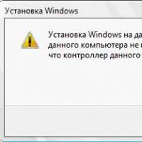 If installing Windows to this disc is not possible
 During installation of Windows "Make sure that the controller of this disc is included in the computer's BIOS menu.