Network programming - TCP. Client-server application on a TCP stream socket Input and output data streams
Servers that implement these protocols in corporate network provide the client with an IP address, gateway, netmask, name servers, and even a printer. Users do not need to manually configure their hosts in order to use the network.
The QNX Neutrino operating system implements another plug and play protocol called AutoIP, which is a draft of the IETF automatic tuning... This protocol is used on small networks to assign IP addresses to hosts that are link-local. The AutoIP protocol independently determines the IP address local to the channel, using a negotiation scheme with other hosts and without contacting a central server.
Using PPPoE Protocol
PPPoE stands for Point-to-Point Protocol over Ethernet. This protocol encapsulates data for transmission over a bridged Ethernet network.
PPPoE is a user connection specification Ethernet networks to the Internet via a broadband connection, such as a dedicated digital subscriber line, wireless device, or cable modem. Using PPPoE protocol and broadband modem provides users with local computer network individual authenticated access to high-speed data networks.
PPPoE combines Ethernet with PPP to efficiently create a separate connection to a remote server for each user. Access control, connection accounting, and service provider selection are user-specific, not host-specific. The advantage of this approach is that neither the telephone company nor the Internet service provider has to provide any special support for this.
Unlike dial-up connections, DSL and cable modem connections are always active. Since the physical connection to a remote service provider is shared by multiple users, an accounting method is needed that registers the senders and destinations of traffic and also charges users. PPPoE allows a user and a remote host who are participating in a communication to learn each other's network addresses during an initial exchange called detection(discovery). After a session between an individual user and remote node(for example, by your ISP) is set, this session can be monitored for charging. In many homes, hotels and corporations, Internet access is shared over digital subscriber lines using Ethernet and PPPoE.
A PPPoE connection consists of a client and a server. The client and server work using any interface that is close to the Ethernet specifications. This interface is used to issue IP addresses to clients with the binding of these IP addresses to users and, optionally, to workstations, instead of authentication based only workstation... The PPPoE server creates a point-to-point connection for each client.
Establishing a PPPoE Session
In order to create a PPPoE session, you should use the servicepppoed... Moduleio-pkt- * nProvides PPPoE protocol services. First you need to runio-pkt- *withsuitable driver... Example:
Client-server application on TCP streaming socket
In the following example, we use TCP to provide ordered, reliable two-way byte streams. Let's build a complete application that includes a client and a server. We first demonstrate how to construct a server on TCP streaming sockets, and then a client application to test our server.
The following program creates a server that receives connection requests from clients. The server is built synchronously, therefore, the execution of the thread is blocked until the server agrees to connect to the client. This app demonstrates a simple server that responds to a client. The client ends the connection by sending a message to the server
TCP Server
The creation of the server structure is shown in the following functional diagram:
Here is the complete code for the SocketServer.cs program:
// SocketServer.cs using System; using System.Text; using System.Net; using System.Net.Sockets; namespace SocketServer (class Program (static void Main (string args) (// Set the local endpoint for the socket IPHostEntry ipHost = Dns.GetHostEntry ("localhost"); IPAddress ipAddr = ipHost.AddressList; IPEndPoint ipEndPoint = new IPEndPoint (ipAddr ); // Create a Tcp / Ip Socket sListener = new Socket (ipAddr.AddressFamily, SocketType.Stream, ProtocolType.Tcp); // Assign the socket to the local endpoint and listen for incoming sockets try (sListener.Bind (ipEndPoint); sListener. Listen (10); // Start listening for connections while (true) (Console.WriteLine ("Waiting for a connection on port (0)", ipEndPoint); // The program pauses, waiting for an incoming connection Socket handler = sListener.Accept (); string data = null; // We waited for a client trying to connect with us byte bytes = new byte; int bytesRec = handler.Receive (bytes); data + = Encoding.UTF8.GetString (bytes, 0, bytesRec); // Show data on the console Console.Write ("Received text: "+ data +" \ n \ n "); // Send a response to the client \ string reply = "Thanks for the request in" + data.Length.ToString () + "characters"; byte msg = Encoding.UTF8.GetBytes (reply); handler.Send (msg); if (data.IndexOf ("
Let's take a look at the structure of this program.
The first step is to establish a local endpoint for the socket. Before opening a socket to listen for connections, you need to prepare a local endpoint address for it. The unique TCP / IP service address is determined by the combination of the host IP address with the service port number that creates the service endpoint.
The Dns class provides methods that return information about the network addresses supported by the device in local network... If a LAN device has more than one network address, the Dns class returns information about all network addresses, and the application must select a suitable address from the array to serve.
Create an IPEndPoint for the server by combining the first host IP address from the Dns.Resolve () method with the port number:
IPHostEntry ipHost = Dns.GetHostEntry ("localhost"); IPAddress ipAddr = ipHost.AddressList; IPEndPoint ipEndPoint = new IPEndPoint (ipAddr, 11000);
Here the IPEndPoint class represents localhost on port 11000. Next, create a stream socket with a new instance of the Socket class. With a local endpoint set up to listen for connections, a socket can be created:
Socket sListener = new Socket (ipAddr.AddressFamily, SocketType.Stream, ProtocolType.Tcp);
Enumeration AddressFamily specifies the addressing schemes that an instance of the Socket class can use to resolve an address.
In the parameter SocketType there are TCP and UDP sockets. In it, you can define, among other things, the following values:
DgramSupports datagrams. The Dgram value requires you to specify Udp for the protocol type and InterNetwork in the address family parameter.
RawSupports access to the underlying transport protocol.
StreamSupports streaming sockets. The Stream value requires Tcp to be specified for the protocol type.
The third and final parameter defines the type of protocol required for the socket. In the parameter ProtocolType you can specify the following most important values - Tcp, Udp, Ip, Raw.
The next step should be to assign the socket using the method Bind ()... When a socket is opened by the constructor, no name is assigned to it, only a descriptor is reserved. The Bind () method is called to assign a name to the server socket. For the client socket to be able to identify the TCP streaming socket, the server program must name its socket:
SListener.Bind (ipEndPoint);
The Bind () method binds the socket to the local endpoint. You must call the Bind () method before any attempts to call the Listen () and Accept () methods.
Now, having created a socket and associated a name with it, you can listen to incoming messages using the method Listen ()... In a listening state, the socket will wait for incoming connection attempts:
SListener.Listen (10);
The parameter defines backlog indicating maximum number connections pending in the queue. In the given code, the value of the parameter allows up to ten connections to be accumulated in the queue.
In the listening state, one must be ready to consent to the connection with the client, for which the method is used Accept ()... This method obtains a client connection and completes the client / server name association. The Accept () method blocks the caller's thread until a connection arrives.
The Accept () method retrieves the first connection request from the pending request queue and creates a new socket to handle it. Although a new socket is created, the original socket continues to listen and can be multithreaded to receive multiple connection requests from clients. No server application should close the listening socket. It should continue to work alongside the sockets created by the Accept method to handle incoming client requests.
While (true) (Console.WriteLine ("Waiting for a connection on port (0)", ipEndPoint); // The program pauses, waiting for an incoming connection Socket handler = sListener.Accept ();
Once the client and server have established a connection between themselves, you can send and receive messages using the methods Send () and Receive () Socket class.
The Send () method writes outgoing data to the socket to which the connection is established. The Receive () method reads incoming data onto a stream socket. When using a TCP-based system, a connection must be established between the sockets before executing the Send () and Receive () methods. The exact protocol between the two interacting entities must be determined ahead of time so that the client and server applications do not block each other, not knowing who should send their data first.
When the exchange of data between the server and the client is completed, you need to close the connection using the methods Shutdown () and Close ():
Handler.Shutdown (SocketShutdown.Both); handler.Close ();
SocketShutdown is an enumeration containing three values to stop: Both- stops sending and receiving data by the socket, Receive- stops receiving data on the socket, and Send- stops sending data by the socket.
The socket is closed when the Close () method is called, which also sets the Connected property of the socket to false.
Client on TCP
The functions used to create a client application more or less resemble a server application. As with the server, the same methods are used to determine the endpoint, instantiate the socket, send and receive data, and close the socket.
Traveling over network protocols.
TCP and UDP are both transport layer protocols. UDP is a connectionless protocol with unsecured packet delivery. TCP (Transmission Control Protocol) is a connection-oriented protocol with guaranteed packet delivery. First there is a handshake (Hello. | Hello. | Let's chat? | Come on.), After which the connection is considered established. Further, packets are sent back and forth over this connection (there is a conversation), and with a check whether the packet has reached the recipient. If the packet is lost, or arrived, but with a bit checksum, then it is sent again ("repeat, did not hear"). Thus, TCP is more reliable, but it is more complex from the point of view of implementation and, accordingly, requires more clock / memory, which is not the least important for microcontrollers. Examples of application protocols using TCP include FTP, HTTP, SMTP, and many others.
TL; DR
HTTP (Hypertext Transfer Protocol) is an application protocol through which the server sends pages to our browser. HTTP is now ubiquitous on the World Wide Web to retrieve information from websites. The picture shows a light on a microcontroller with an OS on board, in which the colors are set through the browser.
HTTP protocol is textual and quite simple. Actually, this is how it looks GET method sent by the netcat utility to the local IPv6 address of the bulb server:
~ $ nc fe80 :: 200: e2ff: fe58: b66b% mazko 80< The HTTP Method is usually a short, capitalized English word, case sensitive. Every server must support at least the GET and HEAD methods. In addition to the GET and HEAD methods, the POST, PUT and DELETE methods are often used. The GET method is used to request the contents of the specified resource, in our case here is GET / b HTTP / 1.0 where the path / b is responsible for the color (blue). Server response: HTTP / 1.0 200 OK Server: Contiki / 2.4 http://www.sics.se/contiki/ Connection: close Cache-Control: no-cache, no-store, must-revalidate Pragma: no-cache Expires: 0 Content- type: text / html Red is OFF Green is OFF Blue is ON
The status code (we have 200) is part of the first line of the server response. It is a three-digit integer. The first digit indicates the class of the condition. The response code is usually followed by an explanatory phrase in English, separated by a space, which explains to the person the reason for this particular response. In our case, the server worked without errors, everything in a bunch (OK).
Both the request and the response contain headers (each line is a separate header field, the name-value pair is separated by a colon). Headers end with an empty line, after which data can go.
My browser refuses to open the local IPv6 address, so an additional address is written in the microcontroller firmware and the same prefix must also be assigned to the virtual network interface of the simulator:
~ $ sudo ip addr add abcd :: 1/64 dev mazko # linux ~ $ netsh interface ipv6 set address mazko abcd :: 1 # windows ~ $ curl http: //
TCP integrates naturally into the client / server environment (see Figure 10.1). Server Application listens(listen) incoming connection requests. For example, WWW, File Transfer, or Terminal Access services listen for requests from clients. Communication in TCP is initiated by the appropriate subroutines, which initiate the connection to the server (see Chapter 21 on the socket programming interface).
Rice. 10.1. The client calls the server.
In reality, the client can be another server. For example, mail servers can connect to other mail servers to forward e-mail messages between computers.
10.2 TCP Concepts
In what form should applications send data over TCP? How does TCP transfer data to IP? How do the sending and receiving TCP protocols identify the connection between applications and the data items required to implement it? All of these questions are answered in the following sections, which describe basic TCP concepts.
10.2.1 Input and output data streams
Conceptual the connection model assumes that the application sends a stream of data to the peer application. At the same time, it is able to receive a stream of data from its connection partner. TCP provides full duplex(full duplex) mode of operation in which simultaneously two streams data (see Figure 10.2).

Rice. 10.2. Applications exchange data streams.
10.2.2 Segments
TCP can transform the data stream leaving the application into a form suitable for placement in datagrams. How?
The application transmits data in TCP, and this protocol puts it in output buffer(send buffer). Next, TCP cuts chunks of data from the buffer and sends them, adding a header (in this case, segments- segment). In fig. 10.3 shows how data from output buffer TCP is packaged into segments. TCP transmits the segment to IP for delivery as a separate datagram. Packing the data into chunks of the correct length ensures that the data is sent efficiently, so TCP will wait until the corresponding amount of data appears in the output buffer before creating a segment.

Rice. 10.3 Creating a TCP segment
10.2.3 Ejection
However, large amounts of data are often impossible to apply to real-world applications. For example, when an end user client program initiates an interactive session with remote server, then the user only enters commands (followed by pressing the key Return).
The user's client program needs TCP to know about sending data to the remote host and to do this immediately. In this case, use ejection(push).
If you look at the operations in an interactive session, you can find many segments with little data, and what's more, bumps can be found in almost every segment of data. However, push should not be applied during file transfers (except for the very last segment), and TCP will be able to most efficiently pack data into segments.
10.2.4 Urgent data
The application forwarding model assumes the application of an ordered stream of bytes that travels to the destination. Referring again to the interactive session example, suppose the user pressed the key attention(attention) or break(interrupt). The remote application must be able to skip interfering bytes and respond to the keystroke as soon as possible.
Mechanism urgent data(urgent data) marks special information in the segment as urgent. By this, TCP informs its peer that the segment contains urgent data, and can indicate where it is. The partner should forward this information to the destination application as soon as possible.
10.2.5 Application ports
The client must identify the service he wants to access. This is done through the specification of the host's service IP address and its TCP port number. As with UDP, TCP port numbers range from 0 to 65535. Ports in the range from 0 to 1023 are referred to as well-known and are used to access standard services.
Several examples of well-known ports and their corresponding applications are shown in Table 10.1. Services Discard(port 9) and chargen(port 19) are the TCP versions of the services we already know from UDP. Remember that TCP port 9 traffic is completely isolated from UDP port 9 traffic.
Table 10.1 Commonly Known TCP Ports and their Corresponding Applications
| Port | Application | Description |
|---|---|---|
| 9 | Discard | Canceling all incoming data |
| 19 | Chargen | Symbol generator. Character stream exchange |
| 20 | FTP-Data | FTP data forwarding port |
| 21 | FTP | Port for FTP conversation |
| 23 | TELNET | Port for remote Telnet registration |
| 25 | SMTP | SMTP port |
| 110 | POP3 | Fetching mail service for personal computers |
| 119 | NNTP | Access to online news |
What about the ports used by clients? In rare cases, the client does not work through a well-known port. But in such situations, wanting to open a connection, it often asks the operating system to assign an unused and unreserved port to it. At the end of the connection, the client is obliged to return this port back, after which the port can be reused by another client. Since there are more than 63,000 TCP ports in the unreserved number pool, client port limits can be ignored.
10.2.6 socket addresses
As we already know, the combination of IP address and port for communication is called socket. A TCP connection is fully identified by the socket address at each end of that connection. In fig. Figure 10.4 shows the connection between a client at socket (128.36.1.24, port = 3358) and a server at socket (130.42.88.22, port = 21).

Rice. 10.4. Socket addresses
Each datagram header contains the source and destination IP addresses. It will be seen later that the source and destination port numbers are indicated in the TCP segment header.
Typically, a server is capable of managing multiple clients at the same time. Unique socket addresses of a server are assigned simultaneously to all of its clients (see Figure 10.5).

Rice. 10.5. Multiple clients connected to server socket addresses
Since the datagram contains a TCP connection segment identified by IP addresses and ports, it is very easy for a server to keep track of multiple client connections.
10.3 TCP Reliability Mechanism
In this section, we will look at the TCP mechanism used to reliably deliver data while maintaining forwarding order and avoiding loss or duplication.
10.3.1 Numbering and confirmation
TCP uses numbering and acknowledgment (ACK) to ensure reliable data transfer. The TCP numbering scheme is somewhat unusual: each connection-forwarded octet is considered as having a sequential number. TCP segment header contains sequence number the first data octet of this segment.
The receiver is required to acknowledge receipt of the data. If no ACK arrives within the timeout interval, the data is retransmitted. This method is called positive acknowledgment with relay(positive acknowledgment with retransmission).
The receiver of TCP data strictly controls incoming sequence numbers to ensure that the data is received in a consistent manner and that there are no missing parts. Since ACKs can be randomly lost or delayed, duplicate segments can arrive at the recipient. Sequence numbers allow you to identify duplicate data that is then discarded.
In fig. 10.6 shows a simplified look at TCP timeout and retransmission.

Rice. 10.6. Timeout and retransmission in TCP
10.3.2 Port, Sequence, and ACK Fields in the TCP Header
As shown in fig. 10.7, the first few fields of the TCP header provide room for the source and destination ports, the sequence number of the first byte of embedded data, and the ACK equal to the sequence number next byte expected on the other end. In other words, if TCP receives all bytes up to the 30th from its peer, this field will have a value of 31, indicating the segment to forward.

Rice. 10.7. Initial Values in TCP Header Fields
One small detail should be noted. Suppose TCP has sent bytes from 1 to 50 or more there is no data to send. If data is received from a partner, TCP is obliged to acknowledge its receipt, for which it will send a header with no data connected to it. Naturally, this header contains the ACK value. The sequence field contains the value 51, i.e. the number of the next byte that intends send TCP. When TCP sends the next data, the new TCP header will also have a value of 51 in the sequence field.
10.4 Establishing a connection
How do the two applications connect? Before communication, each of them calls a subroutine to form a block of memory that will be used to store the TCP and IP parameters of this connection, for example, socket addresses, current sequence number, initial value of the lifetime, etc.
The server application waits for a client to appear, which, wanting to access the server, issues a request for compound(connect) identifying the IP address and port of the server.
There is one technical peculiarity. Each side begins the numbering of each byte not with one, but with random sequence number(below we will find out why this is done). The original specification advises: generate an initial sequence number based on a 32-bit external timer that increments approximately every 4 μs.
10.4.1 Connection script
The connection procedure is often referred to as a three-way handshake because three messages are exchanged — SYN, SYN, and ACK — to establish a connection.
During connection setup, partners exchange three important pieces of information:
1. The amount of buffer space for receiving data
2. The maximum amount of data carried in the incoming segment
3. Starting sequence number used for outgoing data
Note that each of the parties applies operations 1 and 2 to indicate the limits within which the other party will operate. A personal computer can have a small receive buffer, and a supercomputer can have a huge buffer. The memory structure of a personal computer can limit the incoming portions of data to 1 KB, and the supercomputer is controlled with large segments.
The ability to control how the other party sends data is an important property for TCP / IP scalability.
In fig. 10.8 shows an example of a connection script. Very simple starting sequence numbers are presented so as not to overwhelm the drawing. Note that in this figure, the client is able to receive larger segments than the server.

Rice. 10.8. Establishing a connection
The following operations are performed:
1. The server is initialized and becomes ready to connect to clients (this state is called passive open).
2. The client asks TCP to open a connection to the server at the specified IP address and port (this state is called active open).
3. The client TCP receives the initial sequence number (in this example - 1000) and sends sync segment(synchronize segment - SYN). This segment carries the sequence number, the receive window size (4K), and the largest segment the client can accept (1460 bytes).
4. When a SYN arrives, the server TCP receives mine starting sequence number (3000). It sends a SYN segment containing a starting sequence number (3000), ACK 1001 (which means the first byte sent by the client is numbered 1001), the receive window size (4K), and the largest segment the server can receive (1024 bytes).
5. The client TCP, having received the SYN / ACK message from the server, sends back ACK 3001 (the first byte of the data sent by the server should be numbered 3001).
6. Client TCP instructs its application to open a connection.
7. The server TCP, having received an ACK message from the client TCP, informs its application about the opening of the connection.
The client and server announce their rules for received data, synchronize their sequence numbers and become ready to exchange data. The TCP specification also permits another (not very successful) scenario, when peer applications simultaneously actively open each other.
10.4.2 Setting IP Parameter Values
The application's connection request can also specify parameters for the IP datagrams that will carry the data for that connection. If no specific parameter value is specified, the default value is used.
For example, an application can select the desired value for IP priority or service type. Since each of the connected parties independently sets its own priority and type of service, theoretically, these values may differ for different directions of data flows. As a rule, in practice, the same values are used for each direction of exchange.
When an application uses security options for government or military agencies, each of the connection endpoints must use the same security levels, or the connection will not be established.
10.5 Data transfer
The data transfer begins after the completion of the three-step confirmation of the connection creation (see Fig. 10.9). The TCP standard allows normal data to be included in acknowledgment segments, but it will not be delivered to the application until the connection is complete. For ease of numbering, 1000-byte messages are used. Each TCP header segment has an ACK field that identifies the sequence number of the byte that is expected to be received from the peer on the connection..

Rice. 10.9. Simple data flow and ACK
The first segment sent by the client contains bytes from 1001 to 2000. Its ACK field should contain a value of 3001, which indicates the sequence number of the byte that is supposed to be received from the server.
The server responds to the client with a segment containing 1000 bytes of data (starting at 3001). Its TCP header ACK field will indicate that bytes 1001 through 2000 have already been successfully received, so the next expected segment sequence number should be 2001.
The client then sends segments starting with bytes 2001, 3001, and 4001 in the specified sequence. Note that the client does not expect an ACK after each of the segments sent. The data is sent to the partner until its buffer space is full (we will see below that the recipient can very accurately indicate the amount of data sent to him).
The server conserves bandwidth by using a single ACK to indicate successful forwarding of all segments.
In fig. 10.10 shows the data transfer when the first segment is lost. When the timeout expires, the segment is retransmitted. Note that upon receipt of the lost segment, the receiver sends one ACK confirming that both segments were sent.

Rice. 10.10. Data loss and retransmission
10.6 Closing a connection
The normal termination of a connection is accomplished using the same triple handshake procedure as when opening a connection. Each of the parties can start closing the connection in the following scenario:
A:
B:"Good".
V:"I finished the job too."
A:"Good".
The following scenario is also acceptable (although it is rarely used):
A:"I'm done. There is no more data to send."
V:"Good. However, there is some data ..."
V:"I finished the job too."
A:"Good".
In the example below, the connection closes the server, as is often the case for client / server communications. In this case, after the user enters in the session telnet logout commands, the server initiates a request to close the connection. In the situation shown in Fig. 10.11, the following actions are performed:
1. An application on the server tells TCP to close the connection.
2. The TCP server sends a Final Segment (FIN) informing its peer that there is no more data to send.
3. The client's TCP sends an ACK on the FIN segment.
4. The client's TCP tells its application that the server wants to close the connection.
5. The client application tells its TCP to close the connection.
6. The client's TCP sends a FIN message.
7. The TCP server receives the FIN from the client and responds with an ACK message.
8. The TCP server instructs its application to close the connection.

Rice. 10.11. Closing a connection
Both sides can start closing at the same time. In this case, the normal connection closure is completed after each partner sends an ACK message.
10.6.1 Abrupt termination
Each side can request abrupt close of the connection. This is acceptable when an application wishes to terminate a connection, or when TCP encounters a serious communication problem that it cannot resolve on its own. Abrupt termination is requested by sending one or more reset messages to the peer, as indicated by a specific flag in the TCP header.
10.7 Flow control
The TCP receiver is loaded with the incoming data stream and determines how much information it can receive. This limitation affects the TCP sender. The explanation below for this mechanism is conceptual, and developers can implement it in different ways in their products.
During connection setup, each partner allocates space for the connection's input buffer and notifies the other side of this. Typically, the buffer size is expressed as an integer number of maximum segment sizes.
The data stream enters the input buffer and is stored there before being sent to the application (determined by the TCP port). In fig. 10.12 shows an input buffer capable of accepting 4KB.

Rice. 10.12. Receiving window of the input buffer
The buffer space fills up as data arrives. When the receiving application fetches data from the buffer, the freed space becomes available for new incoming data.
10.7.1 Receiving window
Receiving window(receive window) - any space in the input buffer not yet occupied by data. The data remains in the input buffer until consumed by the target application. Why doesn't the app pick up the data right away?
A simple scenario will help answer this question. Suppose a client has uploaded a file to an FTP server running on a very busy multiuser computer. The FTP program must then read the data from the buffer and write it to disk. When the server performs disk I / O operations, the program waits for those operations to complete. At this time, another program may start (for example, according to a schedule) and while the FTP program starts again, the following data will already arrive in the buffer.
The receive window expands from the last acknowledged byte to the end of the buffer. In fig. 10.12 first, the entire buffer is available and therefore a 4KB receive window is available. When the first KB arrives, the receiving window will be reduced to 3 KB (for simplicity, we will assume that each segment is 1 KB in size, although in practice this value varies depending on the needs of the application). The arrival of the next two 1 KB segments will reduce the receiving window to 1 KB.
Each ACK sent by the receiver contains information about the current state of the receiving window, depending on which the data flow from the source is regulated.
For the most part, the size of the input buffer is set at connection startup time, although the TCP standard does not specify how to handle this buffer. The input buffer can grow or shrink to provide feedback to the sender.
What happens if an incoming segment can be placed in the receiving window, but it did not arrive in order? It is generally assumed that all implementations store the received data in the receive window and send an acknowledgment (ACK) only for a whole contiguous block of several segments. This is the correct method, because otherwise discarding out-of-order data will significantly degrade performance.
10.7.2 Submit window
The system transmitting the data must keep track of two characteristics: how much data has already been sent and confirmed, and the current size of the receiver's receiving window. Active dispatch space(send space) expands from the first unacknowledged octet to the left of the current receiving window. Part window used by to send, indicates how much more additional data can be sent to the partner.
The initial sequence number and the initial size of the receiving window are set during connection setup. Rice. 10.13 illustrates some of the features of the data transfer mechanism.
1. The sender starts with a 4KB send window.
2. The sender sends 1 KB. A copy of this data is retained until an acknowledgment (ACK) is received, as it may need to be retransmitted.
3. The ACK message for the first KB arrives, and the next 2 KB of data is sent. The result is shown in the third part from the top of Fig. 10.13. The storage of 2 KB continues.
4. Finally, an ACK arrives for all transmitted data (ie all received by the receiver). ACK restores the send window size to 4K.

Rice. 10.13. Send window
Several interesting features should be pointed out:
S The sender does not wait for an ACK for each of the data segments it sends. The only transfer limitation is the size of the receive window (for example, the sender should only send 4K single-byte segments).
S Suppose the sender sends data in several very short segments (for example, 80 bytes). In this case, the data can be reformatted for more efficient transmission (for example, into a single segment).
10.8 TCP Header
In fig. 10.14 shows the segment format (TCP header and data). The header begins with the source and destination port IDs. Next next field serial number(sequence number) indicates the position in the outgoing data stream that this segment occupies. Field ACK(acknowledgment) contains information about the expected next segment to appear in the input data stream.

Rice. 10.14. TCP segment
There are six flags:
Field data bias(Data Offset) contains the size of the TCP header in 32-bit words. The TCP header must end at a 32-bit boundary.
10.8.1 Option for maximum segment size
Parameter "maximum segment size"(maximum segment size - MSS) is used to advertise the largest chunk of data that can be received and processed by the system. However, the title is somewhat inaccurate. Usually in TCP segment treated as header plus data. but maximum segment size defined as:
The largest datagram you can accept is 40
In other words, the MSS reflects the greatest payload in the receiver with a length of TCP and IP headers of 20 bytes. If there are additional parameters, their length should be subtracted from the total size. Therefore, the amount of data that can be sent in a segment is defined as:
MSS declared value + 40 - (sum of TCP and IP header lengths)
Typically, peers exchange MSS values in the initial SYN messages when a connection is opened. If the system does not advertise a maximum segment size value, the default value of 536 bytes is used.
The size of the maximum segment is encoded with a 2-byte preamble followed by a 2-byte value, i.e. the largest value will be 2 16 -1 (65 535 bytes).
MSS imposes a hard limit on data sent to TCP: the receiver will not be able to process large values. However, the sender is using segments smaller, since the MTU along the path is also determined for the connection.
10.8.2 Using header fields in a connection request
The first segment sent to open a connection has a SYN flag of 1 and an ACK flag of 0. The initial SYN is the only one a segment that has an ACK field of 0. Note that security uses this feature to detect incoming requests for a TCP session.
Field serial number contains starting sequence number(initial sequence number), field window - initial size receiving window. The only TCP parameter currently defined is the maximum segment size (when not specified, the default is 536 bytes) that TCP expects to receive. This value is 32 bits long and is usually present in the connection request in the field options(Option). The TCP header containing the MSS value is 24 bytes long.
10.8.3 Using header fields in the connection response
In an enable response to a connection request, both flags (SYN and ACK) are equal to 1. The responding system indicates the initial sequence number in the corresponding field, and the size of the receive window in the field Window... The maximum segment size that the recipient wishes to use is usually found in the response to the connection request (in the options). This value can be different from the value of the party requesting the connection, i.e. two different values can be used.
A connection request can be rejected by specifying a reset flag (RST) with a value of 1 in the response.
10.8.4 Selecting the starting sequence number
The TCP specification assumes that during connection establishment, each party chooses starting sequence number(at the current value of the 32-bit internal timer). How is this done?
Imagine what happens when the system crashes. Suppose the user opened a connection just before the crash and sent a small amount of data. After recovery, the system no longer remembers anything that was done before the crash, including already running connections and assigned port numbers. The user re-establishes the connection. The port numbers do not match the original assignments, and some of them may already be in use by other connections established a few seconds before the crash.
Therefore, the other side at the very end of the connection may not know that its partner went through a collapse and his work was then restored. All of this will lead to serious disruptions in work, especially when it takes a long time until old data travels over the network and mixes with data from the newly created connection. Timer selection of the fresh start eliminates such problems. The old data will have a different numbering than the sequence number range of the new connection. Hackers, when falsifying the source IP address for a trusted host, try to gain access to computers by specifying a predictable starting sequence number in the message. A cryptographic hash function based on internal keys is the best way to select secure seed numbers.
10.8.5 Common use of fields
When preparing the TCP header for transmission, the sequence number of the first octet of the transmitted data is indicated in the field sequential number(Sequence Number).
The next octet number expected from the connection partner is entered in the field confirmation(Acknowledgment Number) when the ACK bit is set to 1. Field window(Window) is for the current size of the receiving window. This field contains the number of bytes from the confirmation number that can be accepted... Note that this value allows precise control of the data flow. Using this value, the partner indicates the real state of the receiving window during the exchange session.
If the application points to a TCP push operation, then the PUSH flag is set to 1. The receiving TCP MUST respond to this flag by quickly delivering data to the application as soon as the sender wants to send it.
The URGENT flag, if set to 1, implies urgent data transfer, and the corresponding pointer MUST refer to the last octet of urgent data. A typical use for urgent data is to send cancel or interrupt signals from the terminal.
Urgent data is often called out-of-band information(out-of-band). However, this term is inaccurate. Expedited data is sent on a regular TCP stream, although some implementations may have special mechanisms to tell the application to receive urgent data, and the application must check the contents of the urgent data before all the bytes of the message arrive.
The RESET flag is set to 1 to abort the connection. The same flag is set in the response when a segment arrives that is not associated with any of the current TCP connections.
The FIN flag is set to 1 for connection close messages.
10.8.6 Checksum
The IP checksum is for the IP header only, and the TCP checksum is calculated for the entire segment as well as the pseudo-header generated from the IP header. During the calculation of the TCP checksum, the corresponding field is set to 0. In fig. 10.15 shows a pseudo-header very similar to the one used in the UDP checksum.

Rice. 10.15. The pseudo-header field is included in the TCP checksum
The TCP length is calculated by adding the TCP header length with the data length. TCP checksum is compulsory, not like UDP. The checksum of the received segment is first calculated by the receiver and then compared with the contents of the checksum field of the TCP header. If the values do not match, the segment is discarded.
10.9 TCP Segment Example
Rice. 10.16, analyzer operation protocol Sniffer by Network General, is a sequence of TCP segments. The first three segments establish a connection between the client and the server Telnet... The last segment carries 12 bytes of data.

Rice. 10.16. Displaying TCP Header by Sniffer Analyzer
Analyzer Sniffer translates most values to decimal. However, the flag values are output as hexadecimal. The flag with the value 12 is 010010. The checksum is also displayed in hexadecimal.
10.10 Session support
10.10.1 Window probing
A fast sender and a slow receiver can form a 0 byte receive window. This result is called closing the window(close window). When there is free space to update the receive window size, ACK is used. However, if such a message is lost, both parties will have to wait indefinitely.
To avoid this situation, the sender sets stored timer(persist timer) when the window is closed. The timer value is the retransmission timeout. When the timer expires, a segment is sent to the partner. sounding window(window probe; some implementations include data as well). Probing causes the peer to send back an ACK that reports the current status of the window.
If the window is still zero size, the value of the stored timer is doubled. This process is repeated until the timer reaches a maximum of 60 seconds. TCP will continue to send probe messages every 60 seconds - until the window is opened, until the user completes the process, or until the application timed out.
10.11 Logging out
10.11.1 Timeout
The connection partner can crash or be completely interrupted due to a gateway or communication failure. There are several mechanisms to prevent TCP from re-sending data.
Upon reaching the first threshold for retransmission (relaying), TCP tells IP to check the failed router and at the same time informs the application of the problem. TCP continues to send data until the second boundary value is reached, and only then terminates the connection.
Of course, before this happens, an ICMP message may arrive stating that the destination is unreachable for some reason. In some implementations, even then, TCP will continue to try to access the destination until the timeout interval expires (after which the problem may be fixed). Next, the application is informed that the destination is unreachable.
The application can set its own data delivery timeout and perform its own operations at the end of this interval. The connection is usually disconnected.
10.11.2 Maintaining the connection
When an incomplete connection has data to transfer for a long time, it gets the inactive status. During a period of inactivity, a network crash or loss of physical links can occur. As soon as the network becomes operational again, the partners will continue to exchange data without interrupting the communication session. This strategy was in line with the requirements of the Ministry of Defense.
However, any connection - active or inactive - takes up a lot of computer memory. Some administrators need to return unused resources to systems. Therefore, many TCP implementations are able to send a message about keeping the connection(keep-alive), testing inactive connections. Such messages are periodically sent to the partner to verify its existence on the network. ACK messages should be received in response. The use of keepalive messages is optional. If the system has this capability, the application can cancel it by its own means. Estimated period default the timeout for maintaining a connection is a full two hours!
Recall that the application can set its own timer, according to which, at its own level, it will decide to terminate the connection.
10.12 Performance
How efficient is TCP? Many factors affect resource performance, of which memory and bandwidth are the main ones (see Figure 10.17).

Rice. 10.17. TCP performance factors
The bandwidth and latency in the physical network in use will severely limit the bandwidth. Poor data transfer quality results in a large volume of dropped datagrams, which causes retransmission and, as a result, reduces bandwidth efficiency.
The receiving side must provide sufficient buffer space to allow the sender to transfer data without interruption. This is especially important for networks with high latency, where there is a long time interval between sending data and receiving an ACK (and also when negotiating the window size). To maintain a stable data flow from the source, the receiving side must have a window of at least the bandwidth times the delay product.
For example, if the source can send data at a speed of 10,000 bytes / s, and it takes 2 seconds to return an ACK, then on the other side you need to provide a receiving window of at least 20,000 bytes, otherwise the data flow will not be continuous. A receive buffer of 10,000 bytes will cut the throughput in half.
Another important factor for performance is the host's ability to respond to high priority events and quickly execute context switching, i.e. complete some operations and switch to others. The host can interactively support many local users, batch background processes, and dozens of concurrent communication connections. Context switching allows all of these operations to be serviced while hiding the load on the system. Implementations that integrate TCP / IP with the operating system kernel can significantly reduce the overhead of using context switching.
The resources of the computer's CPU are required for the processing of TCP headers. If the processor is unable to quickly compute checksums, it will slow down the transfer rate of data over the network.
In addition, developers should consider simplifying the configuration of TCP parameters so that the network administrator can customize them to suit their local requirements. For example, the ability to adjust the buffer size for bandwidth and network latency will dramatically improve performance. Unfortunately, many implementations do not pay enough attention to this issue and hard-code the communication parameters.
Suppose the network environment is perfect: there are sufficient resources and context switching is faster than cowboys pulling out their revolvers. Will you get excellent performance?
Not always. The quality of TCP software development also matters. Many performance problems have been diagnosed and resolved over the years in various TCP implementations. The best software is RFC 1122, which defines the communication layer requirements for Internet hosts.
Equally important is the exception and the application of the Jacobson, Kern and Partridge algorithms (these interesting algorithms will be discussed below).
Software developers can reap significant benefits by creating programs that eliminate unnecessary transfers of small amounts of data and have built-in timers to free network resources that are not currently being used.
10.13 Performance Improvement Algorithms
Moving on to the rather complex part of TCP, we will look at mechanisms for improving performance and resolving bandwidth bottlenecks. This section discusses the following issues:
■ Slow start(slow start) prevents a large proportion of network traffic from being used for a new session, which can lead to overhead.
■ Recovery from goofy window syndrome(silly window syndrome) prevents poorly designed applications from overloading the network with messages.
■ Delayed ACK(delayed ACK) reduces congestion by reducing the number of independent forward acknowledgment messages.
■ Computed retransmission timeout(computing retransmission timeout) relies on negotiating the real time of the session, reducing the amount of unnecessary retransmissions, but at the same time does not cause large delays for the really necessary data exchanges.
■ Slow down TCP forwarding when overloads on the network allows routers to return to their original mode and share network resources for all sessions.
■ Sending duplicated ACKs(duplicate ACK) when receiving a segment out of sequence, allows peers to re-send before timeout occurs.
10.13.1 Slow start
If all household appliances are turned on at the same time at home, an overload of the electrical network will occur. In computer networks slow start prevents mains fuses from blowing.
A new connection that instantly triggers the transfer of large amounts of data on an already loaded network can lead to problems. The idea behind slow start is to ensure that the new connection has a successful start while slowly increasing the data transfer rate according to the actual network load. The sender is limited by the size of the loading window, not the large receiving window.
Loading window(congestion window) starts with a size of 1 segment. For each segment with a successfully received ACK, the load window is increased by 1 segment as long as it remains smaller than the receive window. If the network is not overloaded, the loading window will gradually reach the size of the receiving window. Under normal forwarding conditions, these windows will be the same size.
Note that the slow start is not that slow. After the first ACK, the size of the load window is equal to 2 segments, and after successfully receiving an ACK for two segments, the size can increase to 8 segments. In other words, the window size grows exponentially.
Suppose instead of receiving an ACK, a timeout situation has occurred. The behavior of the loading window in this case is discussed below.
10.13.2 Clueless Window Syndrome
In the first implementations of TCP / IP, developers faced the phenomenon goofy window syndrome(Silly Window Syndrome - SWS), which showed up quite often. To understand the events taking place, consider the following scenario, which leads to undesirable consequences, but it is quite possible:
1. The sending application sends data quickly.
2. The receiving application reads 1 byte of data from the input buffer (ie slowly).
3. The input buffer fills up quickly after reading.
4. The receiving application reads 1 byte and TCP sends an ACK meaning "I have free space for 1 byte of data."
5. The sending application sends a 1 byte TCP packet over the network.
6. The receiving TCP sends an ACK meaning "Thank you. I received a packet and have no more free space."
7. The receiving application again reads 1 byte and sends an ACK, and the whole process repeats.
A slow receiving application waits a long time for data to arrive and constantly pushes the received information to the left edge of the window, performing a completely useless operation that generates additional traffic on the network.
Real life situations, of course, are not so extreme. A fast sender and a slow receiver will exchange small (relative to the maximum segment size) chunks of data and switch over an almost full receiving window. In fig. 10.18 shows the conditions for the appearance of the "goofy window" syndrome.

Rice. 10.18. Receive window buffer with very small free space
This problem is not difficult to solve. As soon as the receive window shrinks less than the given target size, TCP begins to trick the sender. In this situation, TCP should not point the sender to additional space in the window when the receiving application reads data from the buffer in small chunks. Instead, the released resources should be kept secret from the sender until there are enough of them. The recommended size is one segment, unless the entire input buffer contains a single segment (in the latter case, a size equal to half the buffer is used). The target size to be reported by TCP can be expressed as:
minimum (1/2 input buffer, maximum segment size)
TCP begins to cheat when the window size becomes less than this size, and will tell the truth when the window size is not less than the value obtained by the formula. Note that there is no harm to the sender because the receiving application would still not be able to process most of the data it expects.
The proposed solution can be easily verified in the above case with an ACK output for each of the received bytes. The same method is also suitable for the case when the input buffer can store several segments (as is often the case in practice). The fast sender will fill the input buffer, but the receiver will indicate that it has no free space to store the information, and will not open this resource until its size reaches the whole segment.
10.13.3 Nagle's Algorithm
The sender should, regardless of the recipient, exclude the transfer of very short segments by accumulating data before sending. The Nagle algorithm implements a very simple idea to reduce the number of short datagrams sent over the network.
The algorithm recommends delaying data transfer (and pushing) by waiting for ACK from previously transmitted data. The accumulated data is sent after receiving an ACK on a previously sent piece of information, or after receiving data in the size of a full segment for sending, or after a timeout expires. This algorithm should not be used for real-time applications that need to send data as quickly as possible.
10.13.4 Delayed ACK
Another performance enhancement mechanism is the ACK delay method. Reducing the number of ACKs reduces the amount of bandwidth that can be used to forward other traffic. If the TCP peer delays sending the ACK slightly, then:
■ You can acknowledge the reception of multiple segments with one ACK.
■ The receiving application is able to receive some amount of data within the timeout interval; the output header can be included in the ACK, and it does not require the formation of a separate message.
In order to avoid delays when sending a stream of full-sized segments (for example, when exchanging files), an ACK should be sent at least for every second full segment.
Many implementations use 200ms timeout. But the delayed ACK does not slow down the exchange rate. When a short segment arrives, there is still enough free space in the input buffer to receive new data, and the sender can continue to send (in addition, retransmission is usually much slower). If a whole segment arrives, you need to respond to it with an ACK message at the same second.
10.13.5 Retransmission timeout
After sending the segment, TCP sets a timer and monitors the arrival of the ACK. If no ACK is received within the timeout period, TCP retransmits the segment (relay). However, what should be the time-out period?
If it is too short, the sender will fill the network with forwarding unnecessary segments that duplicate the information already sent. Too long a timeout will prevent you from quickly fixing segments that are really bad during the transfer, which will reduce throughput.
How to choose the right timeout interval? A value that is good for a high-speed LAN is not good for a multi-hit remote connection. This means that the principle of "one value for all conditions" is clearly unsuitable. Moreover, even for an existing specific connection, network conditions can change, and delays can increase or decrease.
Jacobson, Kern and Partridge algorithms (described in articles , Van Jacobson, and Improving Round-Trip Time Estimates in Reliable Transport Protocols, Karn, and Partridge) allow TCP to adapt to changing network conditions. These algorithms are recommended for use in new implementations. We'll cover them briefly below.
Common sense dictates that the best basis for estimating the correct timeout time for a particular connection may be cycle time(round-trip time) as the interval between sending data and receiving confirmation of their receipt.
Good decisions for the following quantities can be obtained from basic statistics (see Figure 10.19) that can help you calculate timeout times. However, there is no need to rely on averages, as more than half of the estimates will be larger than the average. By looking at a couple of deviations, you can get more correct estimates, taking into account the normal distribution and reducing the too long retransmission waiting time.

Rice. 10.19. Distribution of cycle times
There is no need for a large amount of computation to obtain formal mathematical estimates of deviations. Rough estimates can be used based on the absolute value of the difference between the last value and the average estimate:
Last deviation = | Last Cycle - Average |
Another factor to consider in calculating the correct timeout is the change in cycle time due to current network conditions. What happened on the web at the last minute is more important than what happened an hour ago.
Suppose you are calculating a cycle average for a very long session. Even though the network was initially lightly loaded, and we determined 1000 small values, then there was an increase in traffic with a significant increase in latency.
For example, if 1000 values gave an average of 170 units, but then 50 values were measured with an average of 282, then the current average will be:
170 × 1000/1050 + 282 × 50/1050 = 175
More reasonable would be the value smoothed cycle time(Smoothed Round-Trip Time - SRTT), which takes into account the priority of later values:
New SRTT = (1 - α) × (old SRTT) + α × Last cycle value
The α value is between 0 and 1. Increase a results in a greater influence of the current cycle time on the smoothed average. Since computers can quickly divide by powers of 2 by shifting binary numbers to the right, α is always chosen to be (1/2) n (usually 1/8), so:
New SRTT = 7/8 × old SRTT + 1/8 × Last cycle time
Table 10.2 shows how the SRTT formula adjusts to the current SRTT value of 230 when a change in network condition results in a progressive increase in cycle time (assuming no timeout occurs). The values in column 3 are used as the values in column 1 for the next row in the table (i.e., like the old SRTT).
Table 10.2 Calculating the smoothed cycle time
| Old SRTT | Most recent RTT | (7/8) × (old SRTT) + (1/8) × (RTT) |
|---|---|---|
| 230.00 | 294 | 238.00 |
| 238.00 | 264 | 241.25 |
| 241.25 | 340 | 253.59 |
| 253.59 | 246 | 252.64 |
| 252.64 | 201 | 246.19 |
| 246.19 | 340 | 257.92 |
| 257.92 | 272 | 259.68 |
| 259.68 | 311 | 266.10 |
| 266.10 | 282 | 268.09 |
| 268.09 | 246 | 265.33 |
| 265.33 | 304 | 270.16 |
| 270.16 | 308 | 274.89 |
| 274.89 | 230 | 269.28 |
| 269.28 | 328 | 276.62 |
| 276.62 | 266 | 275.29 |
| 275.29 | 257 | 273.00 |
| 273.00 | 305 | 277.00 |
Now there is a question about choosing a value for the retransmission timeout. Analysis of the cycle times shows a significant deviation of these values from the current average. It makes sense to set a limit for the magnitude of deviations (deviations). Good values for retransmission timeout (called Retransmission TimeOut - RTO in RFC standards) are given by the following formula with a smoothed deviation constraint (SDEV):
T = Retransmission Timeout = SRTT + 2 × SDEV
T = SRTT + 4 × SDEV
To calculate the SDEV, the absolute value of the current deviation is first determined:
DEV = | Last Cycle Time - Old SRTT |
The smoothing formula is then used to account for the last value:
New SDEV = 3/4 × old SDEV + 1/4 × DEV
One question remains - what are the initial values? Recommended:
Initial timeout = 3 s
Initial SRTT = 0
Initial SDEV = 1.5 s
Van Jacobson defined a fast algorithm that calculates the retransmission timeout very efficiently.
10.13.6 Example statistics
How well will the timeout calculated above work? When this value was realized, significant performance improvements were observed. An example would be team statistics netstat received on the system tigger- an Internet server that is accessed by many hosts from all over the world.
1510769 packets (314955304 bytes) received in-sequence
System tigger less than 2.5% of the TCP data segments were retransmitted. For one and a half million incoming data segments (the rest are pure ACK messages), only 0.6% was duplicated. It should be borne in mind that the level of loss in the input data approximately corresponds to the level for the output segments. Thus, the useless retransmission traffic makes up about 0.6% of the total traffic.
10.13.7 Calculations after resubmission
The above formulas use the cycle time value as the interval between sending a segment and receiving an acknowledgment. However, suppose that no acknowledgment is received during the timeout period and the data must be re-sent.
Kern's algorithm assumes that the cycle time should not be changed in this case. The current smoothed value of the cycle time and smoothed deviation keep their values until an acknowledgment is received to send a certain segment without resending it. At this point, calculations are resumed based on the stored values and new measurements.
10.13.8 Actions after retransmission
But what happens before confirmation is received? After retransmission, TCP's behavior changes radically, mainly due to data loss from network congestion. Therefore, the response to the re-sending of data will be:
■ Reducing the speed of re-shipment
■ Reduce network congestion by reducing overall traffic
10.13.9 Exponential braking
After retransmission, the timeout interval is doubled. However, what happens if the timer overflows again? The data will be sent again and the retransmission period will double again. This process is called exponential deceleration(exponential backoff).
If mains failure persists, the timeout period will double until the preset maximum value (typically 1 minute) is reached. Only one segment can be sent after the timeout. The timeout also occurs when the predetermined value for the number of data transfers without receiving an ACK is exceeded.
10.13.10 Reducing congestion by reducing the amount of data sent over the network
Reducing the amount of data transferred is somewhat more complex than the mechanisms discussed above. It starts to work, like the already mentioned slow start. But, since a boundary is set for the level of traffic, which can initially lead to problems, the exchange rate will actually slow down due to an increase in the size of the load window for one segment. You need to set border values to really reduce the upload speed. First, the danger threshold is calculated:
Boundary - 1/2 minimum (current loading window, partner receiving window)
If the obtained value is more than two segments, it is used as a boundary. Otherwise, the border is set to two segments. A complete recovery algorithm requires:
■ Set the size of the loading window to one segment.
■ For each ACK received, increase the load window by one segment until the boundary is reached (very much like a slow start mechanism).
■ Then, with each ACK received, add a smaller value to the load window, which is selected based on the rate of increase in one segment for the cycle time (the increase is calculated as MSS / N, where N is the size of the load window in segments).
An ideal scenario might simplify the work of the recovery mechanism. Suppose that the partner's receiving window (and the current loading window) was 8 segments in size before the timeout was detected, and the boundary was defined as 4 segments. If the receiving application instantly reads data from the buffer, the receive window remains at 8 segments.
■ 1 segment is sent (load window = 1 segment).
■ ACK Received — 2 segments are sent.
■ ACK for 2 segments received — 4 segments are sent, (boundary reached).
■ ACK received for 4 segments. 5 segments are sent.
■ ACK received for 5 segments. 6 segments are sent.
■ ACK received for 6 segments. 7 segments are sent.
■ ACK received for 7 segments. 8 segments are sent (the load window is again equal in size to the receive window).
Since, during retransmission, the timeout requires acknowledgment of all sent data, the process continues until the load window reaches the size of the receive window. The events taking place are shown in Fig. 10.20. The size of the window increases exponentially, doubling during the slow start period, and upon reaching the boundary, it increases linearly.

Rice. 10.20. Limiting the transfer rate during congestion
10.13.11 Duplicate ACKs
In some implementations, an optional feature is used - the so-called fast re-shipment(fast retransmit) - in order to speed up the retransmission of data under certain conditions. Its main idea is related to the sending of additional ACKs by the receiver, indicating a gap in the received data.
Receiving an out-of-order segment, the receiver sends back an ACK pointing to the first byte lost data (see Figure 10.21).

Rice. 10.21. Duplicated ACKs
The sender does not instantly retransmit the data because IP can normally deliver data to the recipient without a send sequence. But when several additional ACKs for duplicate data are received (for example, three), then the missing segment will be sent without waiting for the timeout to expire.
Note that each duplicate ACK indicates the receipt of a data segment. A few duplicate ACKs let you know that the network is capable of delivering enough data and therefore is not overloaded. As part of the overall algorithm, a small reduction in the size of the load window is performed with a real increase in network traffic. In this case, the process of radical resizing when restoring work does not apply.
According to the standard Host Requirements(host requirements) TCP must do the same slow start as described above when quenching the source (source quench). However, reporting this is not targeted or effective because the connection receiving this message may not generate too much traffic. Current specification Router Requirements(router requirements) indicates that routers should not send messages about suppression of the source.
10.13.13 TCP Statistics
Finally, let's take a look at the statistical messages of the command netstat, to see many of the mechanisms described above at work.
Segments are named packages.879137 data packets (226966295 bytes)
21815 data packets (8100927 bytes) retransmittedRe-shipment.
132957 ack-only packets (104216 delayed)We note a large number of
delayed ACK.
Probing window openingzero size.
These are SYN and FIN messages.762469 acks (for 226904227 bytes)Alert for packages arriving
out of sequence.
1510769 packets (314955304 bytes)
9006 completely duplicate packets (867042 bytes)The result of the timeout when real
delivery of data.
74 packets with some dup. data (12193 bytes duped)For greater efficiency
some of the data was repackaged to include additional bytes when it was resubmitted.
13452 out-of-order packets (2515087 bytes)
530 packets (8551 bytes) of data after windowPerhaps this data was
included in the sensing messages.
402 packets received after closeThese are follow-up reruns
sending.
108 discarded for bad checksumsInvalid TCP checksum.
0 discarded for bad header offset fields
7 discarded because packet too short
14677 connections established (including accepts)
18929 connections closed (including 643 drops)
4100 embryonic connections dropped
572187 segments updated rtt (of 587397 attempts)Failed change attempts
the cycle time, because the ACK did not have time to arrive before the timeout expires,
26 connections dropped by rexmit timeoutSubsequent unsuccessful attempts
re-sending, which indicates a lost connection.
Probing timeoutszero window.
Checkout timeoutsbroken connection.
472 connections dropped by keepalive
10.14 Compliance with developer requirements
The current TCP standard requires implementations to adhere to a slow start procedure when initializing a connection and use Kern and Jacobson algorithms to estimate retransmission timeout and manage load. Tests have shown that these mechanisms lead to significant performance improvements.
What happens if you install a system that doesn't adhere to these standards? It will not be able to provide adequate performance for its own users, and will be a bad neighbor for other systems on the network, preventing normal operation from being restored after temporary congestion and creating excessive traffic that leads to the dropping of datagrams.
10.15 Barriers to performance
TCP has proven its flexibility, operating over networks with exchange rates of hundreds or millions of bits per second. This protocol has made it possible to achieve good results in modern local area networks with Ethernet, Token-Ring and Fiber Distributed Data Interface (FDDI) topologies, as well as for low-speed communication lines or long-distance connections (like satellite links).
TCP is designed to respond to extreme conditions such as network congestion. However, the current version of the protocol has features that limit performance in promising technologies that offer bandwidths of hundreds and thousands of megabytes. To understand the problems that arise, consider a simple (albeit unrealistic) example.
Suppose that when moving a file between two systems, you want to exchange a continuous stream as efficiently as possible. Let's assume that:
■ The maximum target segment size is 1 KB.
■ Receiving window - 4 Kbytes.
■ The bandwidth allows two segments to be sent in 1 second.
■ The receiving application consumes data as it arrives.
S ACK messages arrive in 2 seconds.
The sender is capable of sending data continuously. After all, when the volume allocated for the window is full, an ACK arrives, allowing the sending of another segment:
After 2 s:
RECEIVE ACK OF SEGMENT 1, CAN SEND SEGMENT 5.
RECEIVE ACK OF SEGMENT 2, CAN SEND SEGMENT 6.
RECEIVE ACK OF SEGMENT 3, CAN SEND SEGMENT 7.
RECEIVE ACK OF SEGMENT 4, CAN SEND SEGMENT 8.
After another 2 s:
RECEIVE ACK OF SEGMENT 5, CAN SEND SEGMENT 9.
If the receive window was only 2 KB, the sender would have to wait one second out of every two before sending the next data. In fact, to keep a continuous stream of data, the receive window must be at least:
Window = Bandwidth × Cycle Time
Although the example is somewhat exaggerated (to provide simpler numbers), the small window can lead to problems with high latency satellite connections.
Now let's take a look at what happens to high-speed connections. For example, if the bandwidth and transfer rate are measured at 10 million bits per second, but the cycle time is 100 ms (1 / 10th of a second), then for a continuous stream, the receive window must store at least 1,000,000 bits, i.e. ... 125,000 bytes. But the largest number that can be written in the header field for a TCP receive window is 65,536.
Another problem arises at high baud rates, since sequence numbers will run out very quickly. If the connection can transfer data at a speed of 4 GB / s, then the sequence numbers should be updated every second. It will not be possible to distinguish between old duplicate datagrams that have been delayed by more than a second as they move around the Internet from fresh new data.
New research is underway to improve TCP / IP and remove the above barriers.
10.16 TCP functions
This chapter focuses on the many features of TCP. The main ones are listed below:
■ Binding ports to connections
■ Initialization of connections by 3-step confirmation
■ Performs a slow start to avoid network congestion
■ Segmentation of data in transit
■ Data numbering
■ Handling incoming duplicate segments
■ Calculating checksums
■ Regulation of data flow through the receiving window and the sending window
■ Termination of the connection in the established way
■ Terminating the connection
■ Forwarding urgent data
■ Positive confirmation of re-shipment
■ Calculating retransmission timeout
■ Reduced return traffic during network congestion
■ Alarm for out-of-order segment arrival
■ Sensing the closing of the receiving window
10.17 TCP states
A TCP connection goes through several stages: the connection is established through the exchange of messages, then the data is sent, and then the connection is closed using the exchange of special messages. Each step in the work of the connection corresponds to a certain condition this connection. The TCP software at each end of the connection constantly monitors the current state of the other side of the connection.
Below we will briefly look at a typical state transition of the server and client located at different ends of the connection. We do not intend to give an exhaustive description of all possible states when transferring data. It is found in RFC 793 and document Host Requirements.
During the establishment of connections, the server and client go through similar sequences of states. The server states are shown in Table 10.3 and the client states are shown in Table 10.4.
Table 10.3 Server state sequence
| Server state | Event | Description |
|---|---|---|
| CLOSED (closed) | A fictitious state before starting a connection. | |
| Passive opening by server application. | ||
| LISTEN (tracking) | The server is waiting for a client connection. | |
| The TCP server receives a SYN and sends a SYN / ACK. | The server received a SYN and sent a SYN / ACK. Goes to wait for ACK. | |
| SYN-RECEIVED | The TCP server receives the ACK. | |
| ESTABLISHED (installed) | ACK received, connection open. |
Table 10.4 Client state sequence
If partners simultaneously tried to connect to each other (which is extremely rare), each would go through the states CLOSED, SYN-SENT, SYN-RECEIVED, and ESTABLISHED.
The end sides of the connection remain in the ESTABLISHED state until one of the sides initiates closing connections by sending a FIN segment. During a normal close, the party initiating that close goes through the states shown in Table 10.5. Her partner goes through the states shown in table 10.6.
Table 10.5 State sequence of the party closing the connection
| Closing side states | Event | Description |
|---|---|---|
| ESTABLISHED | The local application requests to close the connection. | |
| TCP sends FIN / ACK. | ||
| FIN-WAIT-1 | The covering party is waiting for the partner's response. Recall that new data may still be arriving from the partner. | |
| TCP receives ACK. | ||
| FIN-WAIT-2 | The closing side has received an ACK from the partner, but the FIN has not yet arrived. The closing side waits for a FIN, accepting the incoming data. | |
| TCP receives FIN / ACK. | ||
| Sends ACK. | ||
| TIME-WAIT | The connection is maintained in an indeterminate state to allow duplicate data or duplicate FINs that still exist on the network to arrive or drop. The waiting period is twice the maximum segment lifetime estimate. | |
| CLOSED |
Table 10.6 Sequence of partner states to close a connection
| Partner status | Event | Description |
|---|---|---|
| ESTABLISHED | TCP receives FIN / ACK. | |
| CLOSE-WAIT | FIN has arrived. | |
| TCP sends ACK. | ||
| TCP waits for its application to close the connection. At this point, the application can send a fairly large amount of data. | ||
| The local application initiates closing the connection. | ||
| TCP sends FIN / ACK. | ||
| LAST-ACK | TCP is waiting for the final ACK. | |
| TCP receives ACK. | ||
| CLOSED | Removed all connection information. |
10.17.1 Analyzing TCP connection states
Command netstat -an allows you to check the current state of the connection. Connections in states are shown below listen, startup, established, closing and time-wait.
Note that the connection port number is listed at the end of each local and external address. You can see that there is TCP traffic for both the ingress and egress queues.
Pro Recv-Q Send-Q Local Address Foreign Address (state)
Tcp 0 0 128.121.50.145.25 128.252.223.5.1526 SYN_RCVD
Tcp 0 0 128.121.50.145.25 148.79.160.65.3368 ESTABLISHED
Tcp 0 0 127.0.0.1.1339 127.0.0.1.111 TIME_WAIT
Tcp 0 438 128.121.50.145.23 130.132.57.246.2219 ESTABLISHED
Tcp 0 0 128.121.50.145.25 192.5.5.1.4022 TIME_WAIT
Tcp 0 0 128.121.50.145.25 141.218.1.100.3968 TIME_WAIT
Tcp 0 848 128.121.50.145.23 192.67.236.10.1050 ESTABLISHED
Tcp 0 0 128.121.50.145.1082 128.121.50.141.6000 ESTABLISHED
Tcp 0 0 128.121.50.145.1022 128.121.50.141.1017 ESTABLISHED
Tcp 0 0 128.121.50.145.514 128.121.50.141.1020 CLOSE_WAIT
Tcp 0 1152 128.121.50.145.119 192.67.239.23.3572 ESTABLISHED
Tcp 0 0 128.121.50.145.1070 192.41.171.5.119 TIME_WAIT
Tcp 579 4096 128.121.50.145.119 204.143.19.30.1884 ESTABLISHED
Tcp 0 0 128.121.50.145.119 192.67.243.13.3704 ESTABLISHED
Tcp 0 53 128.121.50.145.119 192.67.236.218.2018 FIN_WAIT_1
Tcp 0 0 128.121.50.145.119 192.67.239.14.1545 ESTABLISHED
10.18 Implementation Notes
From the very beginning, TCP was designed to interoperate network equipment from different manufacturers. The TCP specification does not specify exactly how internal implementation structures should work. These questions are left for developers to find the best mechanisms for each specific implementation.
Even RFC 1122 (document Host Requirements - host requirements) leaves plenty of room for variation. Each of the implemented functions is marked with a certain level of compatibility:
■ MAY (Allowed)
■ MUST NOT
Unfortunately, sometimes there are products that do not implement the MUST requirements. As a result, users experience performance degradation.
Some good implementation practices are not considered in the standards. For example, improving security is possible by limiting the use of well-known ports by privileged system processes if this method is supported on the local operating system. To maximize performance, implementations should have as little copying and moving of sent or retrieved data as possible.
Standard API indefined(as well as security policy) so that there is a free field for experimenting with different sets of software tools. However, this may result in different APIs being used on each platform and will prevent application software from being moved between platforms.
In fact, developers base their toolkits on a Socket API borrowed from Berkeley. The importance of the programming interface increased with the advent of WINSock (Windows Socket), which led to a proliferation of new desktop applications that could run on top of any WINSock interface compatible with the TCP / IP stack.
10.19 Further reading
The original TCP standard is defined in RFC 793. Updates, fixes, and interoperability requirements are addressed in RFC 1122. Kern (Kash) and Partridge (Partridge) published an article Improving Round-Trip Estimates in Reliable Transport Protocols In the magazine Proceedings of the ACM SIGCOMM 1987. Jacobson's article Congestion Avoidance and Control appeared in Proceedings of the ACM SIGCOMM 1988 Workshop. Jacobson has also issued several RFCs revising performance improvement algorithms.
 How to update iPad: instructions
 How Do Not Disturb mode works on iPhone
 Nokia 3310 when it came out. How they find us
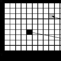 History of computer graphics in Russia 1 history of development of computer graphics
 Complete order: How to organize icons on a smartphone Complete order: How to organize icons on a smartphone
 Xiaomi Huami Amazfit Bip is the best smartwatch without any but even if
 What is Jailbreak and what is it for?