We disassemble the charger from a Siemens mobile phone. How to fix a phone charger. A story on the example of charging from LG How to disassemble the charger
Have you ever wondered what is inside the MacBook charger? The compact power supply has significantly more details than you might expect, including even the microprocessor. In this article, we'll take you apart a MacBook charger to see the many components hidden inside and figure out how they interact to safely deliver much-needed power to your computer.
Most consumer electronics, from your smartphone to your TV, use switching power supplies to convert AC power from a wall outlet to the low-voltage DC used by electronic circuits. Switching power supplies, or more correctly, low-voltage power supplies, get their name from the fact that they turn the power supply on and off thousands of times per second. This is most effective for converting voltages.
The main alternative to switching power supply is the linear power supply, which is much simpler and converts overvoltage to heat. Because of this energy loss, the efficiency of a linear power supply is about 60%, compared to about 85% for a switching power supply. Linear power supplies use a bulky transformer that can weigh up to a kilogram or more, while switching power supplies can use tiny high frequency transformers.
Nowadays, these power supplies are very cheap, but this was not always the case. In the 1950s, switching power supplies were complex and expensive, used in aerospace and satellite technology that needed a lightweight and compact power supply. By the early 1970s, new high-voltage transistors and other technological advances made power supplies significantly cheaper and they were widely used in computers. The introduction of single-chip controllers in 1976 made power converters even simpler, smaller, and cheaper.
Apple's use of switching power supplies began in 1977, when chief engineer Rod Holt designed the switching power supply for the Apple II.
In the words of Steve Jobs:
This switching power supply was as revolutionary as the Apple II logic. Rod didn't get much recognition in the pages of history, but he deserved it. Every computer now uses switching power supplies, and they are all similar in structure to Holt's.
This is a great quote, but it is not entirely correct. The power supply revolution happened much earlier. Robert Boschert began selling switching power supplies in 1974 for everything from printers and computers to the F-14 fighter jet. Apple's design was similar to earlier devices and other computers did not use Rod Holt's design. However, Apple has made extensive use of switching power supplies and pushes the boundaries of charger design with compact, stylish and advanced chargers.
What is inside?
For analysis, we took a Macbook 85W charger model A1172, which is small enough to fit in the palm of your hand. The figure below shows several features that can help distinguish an original charger from a fake one. A bitten apple on the body is an integral attribute (which everyone knows about), but there is a detail that does not always attract attention. Original chargers must have a serial number located under the grounding pin.
As strange as it sounds, the best way to open the charge is to use a chisel or something similar and add a little brute force to it. Apple initially opposed anyone opening their products and inspecting the "insides." Removing the plastic case, you can immediately see the metal radiators. They help cool the powerful semiconductors housed inside the charger.

On the back of the charger you can see the printed circuit board. Some of the tiny components are visible, but most of the circuitry is hidden under the metal heatsinks, held together with yellow tape.

We looked at the radiators and that's enough. To see all the details of the device, of course, you need to remove the radiators. There are significantly more components hidden under these metal parts than would be expected from a small block.

The image below shows the main components of the charger. The AC power goes to the charger and is converted to DC there. Power Factor Correction (PFC) circuitry improves efficiency by ensuring a steady load on the AC line. According to the functions it can perform, the board can be divided into two parts: high-voltage and low-voltage. The high-voltage part of the board, together with the components placed on it, is designed to lower the high-voltage DC voltage and transfer it to the transformer. The low-voltage part receives a constant low-voltage voltage from the transformer and outputs a constant voltage of the required level to the laptop. Below we will look at these schemes in more detail.

AC input to charger
The AC voltage is supplied to the charger via a detachable mains cable plug. The big advantage of switching power supplies is their ability to operate over a wide range of input voltages. By simply changing the plug, the charger can be used anywhere in the world, from European 240 volts at 50 hertz to North American 120 volts at 60 hertz. Capacitors, filters and inductors in the input phase prevent interference from exiting the charger through the power lines. The bridge rectifier contains four diodes that convert AC power to DC.Watch this video for a more visual demonstration of how a bridge rectifier works.

PFC: Power Smoothing
The next step in the charger's operation is the power factor correction circuit, marked in purple. One problem with simple chargers is that they are only charged for a small portion of the AC cycle. When a single device does this, there are no particular problems, but when there are thousands of them, it creates problems for energy companies. This is why regulations require chargers to use power factor correction techniques (they use energy more evenly). You might expect poor power factor to be caused by switched power transmission that turns on and off quickly, but this is not a problem. The problem arises from a non-linear diode bridge that only charges the input capacitor when the AC signal peaks. The idea behind the PFC is to use a DC / DC boost converter before switching the power supply. Thus, the output current sine wave is proportional to the AC waveform.The PFC circuit uses a power transistor to precisely chop the AC input tens of thousands of times per second. Contrary to expectations, this makes the load on the AC lines smoother. The two largest components in the charger are the inductor and the PFC capacitor, which help boost the DC voltage to 380 volts. The charger uses the MC33368 chip to trigger the PFC.
Primary power conversion
The high voltage circuit is the heart of the charger. It takes high DC voltage from the PFC circuit, chops it and feeds it to a transformer to generate a low voltage output from the charger (16.5-18.5 volts). The charger uses an advanced resonant controller that allows the system to operate at very high frequencies up to 500 kilohertz. The higher frequency allows more compact components to be used inside the charger. The IC shown below controls the power supply.SMPS controller - high voltage resonant controller L6599; labeled DAP015D for some reason. It uses a half-bridge resonant topology; in a half-bridge circuit, two transistors control the power through the converter. Common switching power supplies use a PWM (Pulse Width Modulation) controller that adjusts the input time. L6599 adjusts the frequency of the pulse, not the pulse. Both transistors turn on alternately 50% of the time. When the frequency rises above the resonant frequency, the power drops, so the frequency control adjusts the output voltage.

The two transistors turn on and off alternately to reduce the incoming voltage. The converter and capacitor resonate at the same frequency, smoothing the interrupted input into a sine wave.
Secondary power conversion
The other half of the circuit generates the output of the charger. It receives power from the converter and, using diodes, converts it into direct current. Filter capacitors smooth out the voltage that comes from the charger through the cable.The most important role of the low voltage parts of the charger is to keep dangerous high voltages inside the charger to avoid a potentially dangerous shock to the end device. The insulating gap, marked with red dotted lines in the above image, indicates the separation between the main high voltage part and the low voltage part of the device. Both sides are spaced about 6 mm apart.
The transformer transfers power between the primary and secondary devices using magnetic fields instead of a direct electrical connection. The wire in the transformer is triple-insulated for safety. Cheap chargers tend to be stingy with insulation. This poses a security risk. Optocoupler uses an internal beam of light to transmit a feedback signal between the low-voltage and high-voltage parts of the charger. The control IC in the high voltage part of the device uses the feedback signal to adjust the switching frequency in order to keep the output voltage stable.

Powerful microprocessor inside the charger
An unexpected component of the charger is a miniature printed circuit board with a microcontroller, which can be seen in our diagram above. This 16-bit processor continuously monitors charger voltage and amperage. It engages transmission when the charger is connected to the MacBook and disengages transmission when the charger is disconnected. The charger disconnects if there is any problem. This is a Texas Instruments MSP430 microcontroller about the same power as the processor inside the first original Macintosh. The processor in the charger is a low power microcontroller with 1KB flash and only 128 bytes of RAM. It includes a high-precision 16-bit A / D converter.The 68,000 microprocessor from the original Apple Macintosh and the 430 microcontrollers in the charger are not comparable because they have different designs and instruction sets. But for a rough comparison, the 68000 is a 16/32 bit processor clocked at 7.8MHz, while the MSP430 is a 16 bit processor clocked at 16 MHz. The MSP430 is designed for low power consumption and uses approximately 1% of the 68000 power supply.

The gold plated pads on the right are used for programming the chip during production. The 60W MacBook charger uses the MSP430 processor, but the 85W charger uses a general purpose processor that needs to be flashed. It is programmed with a Spy-Bi-Wire interface, which is TI's two-wire version of the standard JTAG interface. After programming, the safety fuse in the chip is destroyed to prevent the firmware from being read or changed.
The three-pin IC on the left (IC202) reduces the charger's 16.5 volts to the 3.3 volts required by the processor. The voltage to the processor is not provided by a standard voltage regulator, but by the LT1460, which produces 3.3 volts with an extremely high accuracy of 0.075%.
Many tiny components on the underside of the charger
Turning the charger over on the PCB reveals dozens of tiny components. The PFC and Power Supply Controllers (SMPS) chips are the main integrated circuits that control the charger. The voltage reference IC is responsible for maintaining a stable voltage even when the temperature changes. The voltage reference IC is the TSM103 / A, which combines two op amps and a 2.5V reference in a single chip. The properties of a semiconductor vary greatly with temperature, so maintaining a stable voltage is not an easy task.These ICs are surrounded by tiny resistors, capacitors, diodes, and other small components. MOS - output transistor, turns the power on and off at the output in accordance with the instructions of the microcontroller. To the left of it are resistors that measure the current transmitted to the laptop.

An isolation gap (marked in red) separates the high voltage from the low voltage output circuit for safety. The dashed red line shows the insulation boundary that separates the low voltage side from the high voltage side. Optocouplers send signals from the low voltage side to the main unit, disconnecting the charger if there is a problem.
A little about grounding. A 1KΩ grounding resistor connects the AC ground pin to the base at the charger output. Four 9.1MΩ resistors connect the internal DC base to the output base. As they cross the border of isolation, security is an issue. Their high stability avoids the danger of shock. The four resistors are not really required, but redundancy exists to ensure the safety and resiliency of the device. There is also a Y capacitor (680pF, 250V) between the internal ground and the output ground. T5A fuse (5A) protects the grounding output.
One of the reasons to install more control components in the charger than usual is the variable output voltage. To deliver 60 watts of voltage, the charger provides 16.5 volts with a 3.6 ohm resistance level. To deliver 85 watts, the potential rises to 18.5 volts and the resistance is 4.6 ohms. This allows the charger to be compatible with laptops that require different voltages. As the current potential rises above 3.6 amperes, the circuit gradually increases the output voltage. The charger switches off urgently when the voltage reaches 90 W.
The control scheme is quite complex. The output voltage is monitored by an op-amp in the TSM103 / A IC, which compares it to a reference voltage generated by the same IC. This amplifier sends a feedback signal through an optocoupler to the SMPS control IC on the high voltage side. If the voltage is too high, the feedback signal will lower the voltage and vice versa. This is a pretty straightforward part, but where the voltage goes from 16.5 volts to 18.5 volts, things get more complicated.
The output current creates a voltage across the tiny 0.005Ω resistors - they look more like wires than resistors. An operational amplifier in the TSM103 / A chip amplifies this voltage. This signal goes to the tiny TS321 op-amp, which starts the build-up when the signal is 4.1A. This signal enters the previously described control circuit, increasing the output voltage. The current signal also goes into a tiny TS391 comparator, which sends the signal to the high voltage device through another optocoupler to reduce the output voltage. This is a protection circuit if the current level gets too high. There are several places on the PCB where zero resistance resistors (i.e. jumpers) can be installed to change the gain of the op amp. This allows the gain accuracy to be adjusted during manufacture.
Magsafe plug
The Magsafe magnetic plug that connects to the Macbook is more sophisticated than it might seem at first glance. It has five spring loaded pins (known as Pogo pins) for connecting to a computer, as well as two power pins, two ground pins. The middle pin is the data connection to the computer.
Inside, Magsafe is a miniature chip that tells the laptop the serial number, type and power of the charger. The laptop uses this data to determine the originality of the charger. The chip also drives an LED indicator for visual status indication. The laptop does not receive data directly from the charger, but only through a chip inside the Magsafe.

Using the charger
You may have noticed that when you connect the charger to the laptop, it takes one to two seconds before the LED sensor is triggered. During this time, a complex interaction takes place between the Magsafe plug, the charger and the Macbook itself.When the charger is disconnected from the laptop, the output transistor blocks the output voltage. If you measure the voltage from the MacBook charger, you will find approximately 6 volts instead of the 16.5 volts you were hoping to see. The reason is the pin is off and you are measuring the voltage across the bypass resistor just below the output transistor. When the Magsafe plug is connected to the Macbook, it starts referring to a low voltage level. The microcontroller in the charger detects this and switches on the power supply within a few seconds. During this time, the laptop has time to get all the necessary information about the charger from the chip inside Magsafe. If all is well, the laptop starts to draw power from the charger and sends a signal to the LED indicator. When the Magsafe plug is disconnected from the laptop, the microcontroller detects a loss of current and cuts off the power supply, which also turns off the LEDs.
A logical question arises - why is the Apple charger so complicated? Other laptop chargers simply provide 16 volts and when plugged into a computer, they immediately apply voltage. The main reason is for safety reasons, to ensure that no voltage is applied until the pins are firmly attached to the laptop. This minimizes the risk of sparks or arcing when plugging in the Magsafe plug.
Why you shouldn't use cheap chargers
The original Macbook 85W charger costs $ 79. But for $ 14, you can buy a charger on eBay that looks similar to the original. So what do you get for the extra $ 65? Let's compare the copy of the charger with the original. From the outside, the charger looks exactly like Apple's original 85W. Except that the Apple logo itself is missing. But if you look inside, the differences become apparent. The photos below show a genuine Apple charger on the left and a copy on the right.
A copy of the charger has half as many parts as the original and the space on the printed circuit board is simply empty. While a genuine Apple charger is overflowing with components, the replica is not designed for much filtering and regulation and lacks the PFC circuitry. The transformer in the replica charger (large yellow rectangle) is much larger than the original model. The higher frequency of Apple's Advanced Resonant Transformer allows for a smaller transformer.

By flipping the charger over and looking at the circuit board, you can see a more complex diagram of the original charger. The copy has only one control IC (in the upper left corner). Since the PFC is completely discarded. In addition, the charging clone is less complicated to operate and does not have a ground connection. You yourself understand what this threatens.
It is worth noting that the copy of the charger uses the Fairchild FAN7602 green PWM controller chip, which is more advanced than you might expect. I think most people expected to see something like a simple transistor generator. And in addition to the copies, unlike the original, a single-sided printed circuit board is used.
In fact, the replica of the charger is of better quality than you would expect when compared to the terrible replicas of the iPad and iPhone chargers. The MacBook Charger Duplicate does not cut all possible components and uses a moderately complex circuitry. This charger also places little emphasis on safety. Isolation of components and separation of high and low voltage areas are applied, with the exception of one dangerous error, which you will see below. The Y capacitor (blue) was installed crookedly and dangerously close to the high voltage side of the optocoupler, creating a risk of electric shock.

Problems with the original from Apple
The irony is that despite the complexity and attention to detail, the Apple MacBook charger is not a fail-safe device. On the Internet, you can find a lot of different photos of burnt, damaged and simply non-working chargers. The most vulnerable part of the original charger is precisely the wire in the area of the Magsafe plug. The cable is rather flimsy and it frays quickly, which leads to its damage, burnout or simply breaking. Apple provides how to avoid damage to the cable, rather than just providing a more powerful cable. In a review on the Apple website, the charger received only 1.5 stars out of 5.
MacBook chargers can also stop working due to internal issues. The photos above and below show burn marks inside Apple's failed charging. Alas, it is impossible to say exactly what caused the fire. Due to the short circuit, half of the components and a good part of the printed circuit board burned out. Below in the photo there is burnt silicone insulation for attaching the board.

Why are original chargers so expensive?
As you can see, Apple's charger has a more advanced design than the counterparts and has additional safety features. However, a genuine charger costs $ 65 more and I doubt the additional components cost more than $ 10 - $ 15. Most of the charger's cost goes into the company's bottom line. The iPhone is estimated to cost 45% of the company's bottom line. Chargers are likely to bring in even more funds. The price for the original from Apple should be significantly lower. The device has many tiny components such as resistors, capacitors and transistors that range in price in the region of one cent. Large semiconductors, capacitors and inductors naturally cost significantly more, but for example, a 16-bit MSP430 processor costs only $ 0.45. Apple explains the high cost not only by marketing and other costs, but also by the high costs of developing a particular charger model. Practical Switching Power Supply Design estimates 9 months of work time to design and improve power supplies in the region of $ 200,000. The company sells about 20 million MacBooks per year. If you invest the cost of development in the cost of the device, it will be only 1 cent. Even if the cost of designing and developing Apple's chargers is 10 times higher, the price will not exceed 10 cents. Despite all this, I do not recommend that you save your money by purchasing analogs of a charger and risking your laptop and even health.And for the rest
Users are not often interested in what is inside the charger. But it's full of interesting things. The seemingly simple charging uses advanced technologies including power factor correction and resonant power supply to produce 85 watts of power in a compact unit. The Macbook charger is an impressive piece of engineering. At the same time, its copies strive to reduce the cost of everything that is possible as much as possible. This is economical, but also a danger to you and your laptop.Causes of malfunctions of the mobile phone charger
The most common reason for the failure of a charger is a careless attitude towards it during operation.
Phone charger repair
Possible causes of breakdowns of the mobile phone charging unit
1. Broken wire at the plug and at the base of the charging unit. You can break the wires when charging is on during calls.
You need to pull the plug out of the phone jack not by the wire, but by the plug body.
2. Failure of the elements of the electronic board of the charger. Very often, the charger is left plugged in and is not removed from the outlet. In this case, the entire electronic board of the charger is constantly energized, which reduces the service life of the radio elements of the board.
The wrong order of switching on and off the charger also leads to premature wear of the unit elements.
If the phone is disconnected from the charger while energized, sudden voltage surges occur that exceed the maximum permissible operating voltage of the cells. This is due to transient processes that occur in the memory when the load is removed (disconnecting the phone) under voltage. With proper operation of the charger, the phone is connected and disconnected with the charger turned off.
DIY phone charger repair technique
You don't need to be a great specialist to find and fix a broken wire from the charging unit to the plug. Wire breakage can be detected when the phone is connected. Having connected the phone to the charger, bend the wire at the plug u of the base of the unit, while simultaneously observing the continuity of the battery charging process.
In these places, wire breaks most often occur. If a break is found at the very base of the plug, then the wire is cut off at a distance of 5-7 mm from the plug. This is necessary in order to be able to solder the whole part of the wire. The soldered wires are insulated separately with a thin heat-shrinkable tube.
When the soldering points of the wires are insulated, a thicker heat shrink tube is put on the plug to stiffen the soldering point. Sometimes a wire break occurs at the very base of the plug, then the plug is completely freed from the plastic seal, and the wires are soldered directly to the plug.
Do not reverse the polarity of the plug wires. The break point is also found with a multimeter in the audible dial mode or visually. The found place of wire breakage is cut with a small margin on both sides. Peel the top insulation off the wire. Then it is cut off, stripped of insulation, twisted and soldered, after putting on a thin heat-shrinkable tube on each wire, and a thicker tube on the common wire.
After soldering, they put thin tubes on the wires and upset them, heating them with a soldering iron. At the end, a thicker tube is put on in place of the upset thin tubes so that the thick tube overlaps them in length. When soldering wires, observe the polarity according to their color. You can purchase a new cord with a plug for your brand of phone from specialized stores. Then phone repair comes down to a simple replacement of the faulty wire.

The type of faulty capacitors
Another common malfunction of a phone charger is a loose contact between the pins of the power plug. The spring-loaded pins of the mains plug often extend from the contact pads on the PCB. To eliminate such a malfunction, it is enough to bend these contacts inside the block.
Open the block cover. It is good if there are screws securing the charger cover, and if they are soldered. In this case, you need to cut a slot along the entire perimeter of the cover with a hacksaw blade with fine teeth. Having eliminated the malfunction, the lid is closed and fixed with tape 1 cm wide.
More complex, but quite affordable for an electrician are device breakdowns associated with the repair of elements of the phone charger board. First of all, they open the memory and take out the board. Repair begins with a visual inspection of the elements of the printed circuit board and the condition of its tracks.

Pulse charger circuit for phone
When inspecting the elements, pay attention to the swelling of the upper part of the capacitors, darkening and violation of the integrity of the resistors. Darkening of the resistors and the tracks below it indicates that the operating temperature has been exceeded. In this case, the resistor itself is checked for resistance and the diodes and transistors are ringed.
The pinout of the transistors and the memory circuit for your phone brand can be found on the Internet. If it was not possible to visually detect a malfunction, turn on the device and measure the input mains voltage. If the mains voltage is present and a faint sound of the pulse transformer is heard, then the output voltage of the unit is measured.

I wonder what the Siemens charger (power supply) consists of and whether it is possible to repair it yourself in case of a breakdown.
First, the block needs to be disassembled. Judging by the seams on the case, this unit is not intended for disassembly, therefore, the thing is disposable and there is no need to pin high hopes in the event of a breakdown.

I had to literally raskurochit the case of the charger, it consists of two tightly glued parts.

Inside there is a primitive board and a few details. Interestingly, the board is not soldered to the 220V plug, but is attached to it with a pair of pins. In rare cases, these contacts can oxidize and lose contact, and you think that the block has broken. But the thickness of the wires going to the mobile phone connector pleased me pleasantly, you don't often find a normal wire in disposable devices, usually it's so thin that it's scary to even touch it).

There were several details on the back of the board, the circuit turned out to be not so simple, but still it is not so complicated that you would not be able to fix it yourself.

Below in the photo are the contacts of the inside of the case.

There is no step-down transformer in the charger circuit; an ordinary resistor plays its role. Then, as usual, a couple of rectifying diodes, a pair of capacitors for rectifying the current, then a choke and finally a zener diode with a capacitor complete the chain and output the reduced voltage to a wire with a connector to a mobile phone.

The connector has only two pins.

Good evening, dear blog readers! For a long time I had a charger for my LG phone, which actually charged me a bunch of other devices. But at one point, I noticed that the phone was not charging as expected. Either the phone is charging, then no, the charging status could change once a second. I put it aside for a long time, bought a new charger, but still the question of how to fix the charger for the phone arose and itched))).
The charger for the phone was composite - a usb wire was inserted into the plug, which in turn was stuck into the phone. There could be two reasons for the inoperability of charging:
- broken usb wire
- malfunction in the plug itself
The first option is easy to check - just replace the wire itself, I’ll say right away that it didn’t help, otherwise there would probably be no point in writing a whole article about it.
There was a fault in the plug ...

In order to find the malfunction and eliminate it, it was necessary to open such a plug. Above it is crowned with gray plastic, which is well glued to the white body of this fork. Of course, if my task were not to fix the Just for fun charger, but to preserve it for future generations for future use, then I would be very confused. But I barbarously broke off the gray top and took out the inner board with pliers.


Quite an ordinary handkerchief from usb-charging the phone. The low-voltage part, the PWM environment and the part where the contacts for connecting to 220 V with a diode bridge and resistance are located are separately highlighted.
Because charging periodically still worked, logic dictated that the contacts in the plug itself were simply leaving. We draw your attention to these contacts:

In turn, the plastic case, where the pins of the plug are attached, also have their own contacts:

Cleaning them, lifting them slightly, as well as wiping the contacts on the side of the board with an eraser solved the problem - after assembly, the charging worked as it should.
If the following cosmetic actions did not help, then you would have to dig deeper. I had to check again if the capacitor was swollen, such a large one, located next to the 220 V contacts on the board. It would also be necessary to "inspect" the input resistance, which plays the role of a fuse (green thing with stripes in the photo above). Judging by my measurements with a multimeter and by the markings on the "belly" of the resistance, its rating in this charge was 10 ohms. If it burns out, it would need to be re-soldered, but this would indicate a problem in the circuit. That is, it would be masking the problem.
Also, one of the problem areas in charging is the transistor, it often burns out.
In the process of working on this post, I needed to edit a video, which I, however, did not upload. If there is a need to trim video, insert simple titles, then there is little point in resorting to some paid products, everything is already in Windows - this is Windows Movie Maker. But as soon as it is necessary to do something more, for example, to enlarge the video, then this program is already not enough. I liked the program, which combines a number of useful qualities - it is powerful enough, easy to learn and cheap. I appreciated her and even acquired... It allows you to easily apply special effects, hide on the video something that you don't want to show (wallet numbers, phones, etc.), stabilize the video, and a whole bunch of other things. Later I will make a small review of it.
Subscribe to blog updates!
Thank you! You have successfully subscribed to new blog content!
How to disassemble charging from iphone 4
Many are worried about the question of How to disassemble the charging from the iPhone 4, because over time it breaks down and needs to be replaced or repaired, which in some cases can be done at home. At the moment, there is a single standard around the world, according to which all chargers are based on USB. With all this, it must be borne in mind that port 2.0 is capable of delivering voltages up to 0.5 A, while many accessories consume even more.
For this reason, manufacturers have moved to more modern and complex formats. The currently produced network adapters provide 4 contacts, or more precisely, the "zero" contact, the power contact, and also a pair of informational ones. The latter are used in modern accessories to identify the charger. In the future, the power controller determines the "fast" or "slow" charging mode.
You can fix a broken charger without the help of others, but for this you need to acquire some tools and do everything intently.

Charger circuit for iPhone
With the modern pace of life, you often find yourself in situations when you need to urgently charge your iPhone, but this can only be done using an unusual charger. If it is out of order, then you can disassemble the case and change the warped part for the newest one.
It is not very difficult to disassemble the iPhone charging, for this you need the following tools:
- Screwdriver Set;
- Sharp stationery knife;
- Glue;
- Fuse.
Read the same
It is necessary to disassemble the iPhone charging on the prepared table, covering it with sheets of snow-white paper. It will be easy to find small bolts on it, as well as details. Place a table lamp next to it and turn it on. Examine the charger closely and determine the type of connection of the parts of its case. If the parts are fastened with self-tapping screws, then they should be unscrewed with careful movements. But in some cases, you will have to tinker a lot, especially when it comes to the latest manufacturer's charging, in which there are no bolts.
Unscrew the bolts carefully.
If they do not give in well, then make a few turns in the opposite direction, and then continue to unscrew. Find all the plastic clips holding the iPhone charging case. They can be closed or hidden. If your charger has open latches, then you must carefully squeeze the tabs out of the grooves. And if the latches are closed, then it is necessary to press in the places where they are installed. It is also useful to pry the iPhone charging part with the tip of a flat screwdriver and remove it.
Macbook power adapter easy disassembly. How to disassemble the Magsafe adapter
The usual method disassemble Macbook power adapter for repair.
DISASSEMBLING A CHINESE CHARGER FOR PHONES FOR 40 RUBLES
Read the same
RETURN Funds FROM PURCHASES ON THE WEB, Get back? ? ? VKONTAKTE COMMUNITY: .
How to disassemble iPhone charging
It will be even more difficult to disassemble a one-time charge, the body of which is one-piece. Specifically, the latest iPhone models are equipped with it. In this case, you will have to take a knife and cut the plastic. Carefully using a sharp knife, cut off one of the parts of the plastic case. Be as careful as possible so as not to destroy the internal components. Replacing the fuse will have to glue both parts.
Remember that you should use a repaired charger with extreme caution, because it can lead to a short circuit.
This is due to the fact that such charges are not designed for repair and long-term implementation. If you do not have a fuse for the iPhone charger under your hand, and you need to fix it as quickly as possible, then use a regular wire. Use it to close the contacts of the fuse connector. After that, charging should proceed in standard mode. But remember that this method should be used only in case of last need.
At first ability, put in a working fuse.

Charger for iPhone disassembled
What to do if iPhone charger breaks down
In such a situation, it is best to purchase a new charger, which can be found at a fully affordable cost in the official online store. But if there is no such ability, then try to carefully disassemble it and replace the fuse with a new one, which should return it to work. The iPhone charger is distinguished primarily by its own compactness.
Read the same
The input voltage is kept in the range of 100-240V. The output is 1A 5V. It's even surprising how the manufacturer managed to fit a real power source in such a small case. In newer models, the case cannot be disassembled without damaging it. It is monolithic, and therefore will have to be cut. Even where plastic of a different color is visible, the construction is one-piece - this is just a decoration.
The only cover is located on the side of the plug. It is well glued.
IPhone Charging Features
The plastic is quite tough, so it is quite possible that you cannot open it without using a hacksaw. Pliers are also useful. The installation is very tight. 3 printed circuit boards are connected into a single whole. One of them is the main one, with two-sided mounting of electronic elements. Others are simpler.
You can fix the iPhone charging, but it is much better not to save on the safety of your device, but to buy a new charger. All actions you take at your own peril and risk, because in case of any mistake, the charger can harm your gadget.
The fact is that the Chinese are very fond of copying analogs and selling them at a more affordable price. Apparently, the Chinese copies have a much simpler design. It is sad when the original charger breaks down, but in such a situation it is important to quickly restore its performance before the iPhone has completely sat down. Now you know what to do in the event of a breakdown, how to disassemble the charger case and install a new fuse.
Post Views: 0
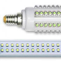 AC LED lighting fixtures are finding their niche and possibly going beyond
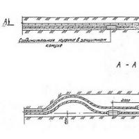 Requirements and prices for laying cables in the ground Scope, definitions
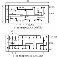 Automotive strobe from laser pointer
 Order 20 UAH to your account. How to borrow money for mts. Additional information on the service
 How to check account replenishment
 How to get a loan on Tele2?
 Responsiveness of SSD on a Miniature Board Which SSD to Buy