Scheme EL Telfer. Electrical electrotelfer scheme. Diagram Electric tap beam. Construction Machines and Equipment, Directory
Telfer device. 220 Volt Connection Circuit
Electrotal device, Telfer equipment, Telfer scheme.
The most popular and easy-to-install and operating a device for lifting goods is an electric. Consider its device on the example of modern Telphers of the MH series produced by Balkankarpode. The total telfer scheme is presented in the picture above.
The fundamental electrical schemes of the Telfer can be found here
Mechanical electric equipment MH includes such important structural elements and assembly units, like a lifting drum, gearbox, coupling, hook suspension, driving trolley, cargo rope.
Lifting electric motor
Asynchronous two-speed electric motor with a conical rotor and a stator and a built-in blessing cone brake. The rotor has the ability to move with less resistance to the axial direction. In the event of a power off, the brake is turned on under the action of the force of the helical springs. A wide range of possible combinations between engines and gearboxes with different technical specifications expand the range of the magnitude of the lifted goods and raising speeds. Additionally, telphers are supplied with two-speed engines - having two stator windings (for operating speed and for accurate shipping). Another delivery option is with frequency converters for the maximum smooth start and braking drives.
Reducer
Double-bearing planetary gearbox installed in the opposite side of the electric motor. Such a design is preferred due to the need to provide a telfer compactness in the radial direction. Three steps of gearbox provide reduction (reduction) of engine speeds, as well as smooth start and braking. Used high-quality materials for the manufacture of gear wheels and other elements of the gearbox. The surfaces of the tooth gears are subjected to cementation and quenching, followed by grinding, which provides a long service life and silent operation of gear wheels with high Reducer efficiency. The elongated kinematic circuit of the transmission torque of the engine to the drum reduces the dynamic load when the electrotal operation is operational.
Housing
The new body has a box-shaped form. It presents a firmly welded design of the type of flange connection between the engine and the gearbox. The rope output to all possible radial directions along the periphery of the case ensures the operation of electrotals in a variety of mounting versions and positions.
Elastic coupling
A special gearbox clutch is applied, located inside the drum between the engine shaft and the gearbox shaft. The elastic package absorbs the peak components of the torque. The coupling design provides unhindered axial movement of the electric motor shaft. At the same time, it protects trees from any radial or tangential movements. Such specificity is associated with the fact that the rotor of the lifting motor is conical. When the drive is turned on, this rotor is shifted along the axis, leaving the engagement with the stator, and when it is turned off - retracts back. Thus, the engine itself is able to slow down the drive during the stop, that is, it has a built-in brake. The kinematic communication of the gearbox with an electric motor is indisputable.
Drum
The lifting drum is a cylindrical hollow structure designed to wet the cargo rope. The surface of the drum is covered with special grooves - "streams", thanks to which the cargo rope is wound with even rows, without overweights and elevations. Together with the rope on the drum, the rod-layer is moved - the device required not so much to lay the rope in the streams, how much to turn on-disconnect the terminal switching switches and excessive descent.
Screw channels for ropes are made over the drum surface. Special rope-making moves in these channels and provides proper winding and unwinding of the rope, regardless of the magnitude of the suspended cargo. The drum has two diaphragms. One of them is installed on the front electric motor flange using a roller bearing. The torque of the outgoing hollow shaft of the gearbox is transmitted to the second diaphragm by means of a slotted connection.
Kanteauchya
New design. To replace the rope-making, you do not need any special tools. The boundaries of the rope deviations to the engine or to the gearbox - ± 4 °. The rowing machine drives the switch of the extreme top and bottom hook position.
Rope
Metal cable of Bulgarian production is used as a cargo rope in electrotals. The most common stock of the rope provides for the rigid seal of one end on the body body and the second end clamp on one edge of the lifting drum. At the same time, the cargo rope itself is brought through the hook suspension unit. Such stock allows you to avoid damage to the rope and prolongs its service life. One end of the rope is fixed to the drum using cable ties. Another end is reinforced to the body of the hoist, or to the hook case or to the drum, first, depending on the way of hanging the cargo. The technical characteristics of the rope provide the necessary reliability and minimal tooling the rope itself and the drum channels.
Hook - set
Hook included: a new design that meets with a polyaste with modern technical safety requirements. Operation is facilitated by the minimum hook's own weight. There is a reliable protection against an arbitrary rope output from channel rollers. The hook suspension contains a freely rotating cable block in a metal casing that prevents the rope falling. The same cargo hook is also freely rotated in both directions for the convenience of the work of solo work.
Trolley
Three types of carts are offered: type N, type K and type D. The housings of the electrotals are attached to them in such a way that it is ensured by optimal timing of cargo to all wheels. Wheels are designed to move the telfer on the shelves of the 2-way beam. Carts can also be electrical (EK), with manual control (RK) or free (SK). The electrical trolley has a motor mechanism of the same type as the cargo lifting mechanism. A normal motor mechanism with an electromagnetic brake is also proposed. A number of traffic rates are very wide. Installation and adjustment of the carts in relation to the profile of a monorail road to be made clarifable. In the case of ordering a two-terminal trolley, the width of the rut and the lines of the rails are specified by the customer. Some electrotals having large sizes in the axial direction are equipped with two chassis trolleys.
Electrical equipment
Electrical equipment Taly includes lifting electric motors, movement electric motors, suspended control panel, starting cabinet, terminal switches block, brake coil and load capacity. The coil and limiter, depending on the configuration, may be absent. The execution of the electric equipment of the Telfer can be special, for example, for operation in a chemically aggressive environment or in a tropical climate.
The voltage and frequency of the electrical network are given by the customer. Operational voltage to the relay coil and contactors - 42 V, frequency -50 Hz. Mostly, electrical equipment is in the team box attached mainly to the hoist case. The end switch of lifting and lowering the cargo is placed in the engine terminal box.
The push-button suspension control panel has the degree of protection of IP65 and can be four-button or six-block for operation as part of a bridge crane. The console has a key mark in its composition to eliminate unauthorized access to the control of the mechanism, as well as the "fungus" button for emergency shutdown drives. For tali with two-speed electric drives, the remote can have a two-position buttons (pushers) or a larger number of buttons - up to 12 pieces.
The secure cabinet contains reversible electromagnetic starters to turn on the drives, the rectifier for powering the brake coil (when presented), terminal blocks for compounds, an electronic unit for a load-capacity limiter (if available) and transformer of the control circuit 380/42. Starters are mounted on DIN rail, but when controlling frequency converters, they are missing.
Contacts of limit and descent circuit switches are installed in the climb engine terminal box. Mechanical communication with the rod-container provides a special thrust on which adjusting crackers are installed.
Brake electromagnetic MH Tali Coil Provides lifting drive braking along with a conical rotor. It is powered by a constant current from the rectifier in the starting closet.
Lift limiter for MH electrothels is supplied by separate order. It is electromechanical, and its device is characterized by simplicity and reliability. If the overload occurs, the limiter rupts its contacts in the lifting control circuit and then only descent is possible. The level of carrying capacity is regulated by a mechanically special trimmed screw.
telfermag.ru.
Electrical circuits
Purpose and device of electrical tags The electric hoist is a small winch, all the elements of which (electric motor, gearbox, brake, cable drum with cutting for styling of the rope, the cabinet with the pads and other necessary devices) are mounted in one case or attached to this body. The electric hoist includes, also, the running part for moving along the monorail path and hook suspension. Typically, the tails are supplied with a suspended remote control.
If you do not take into account the manual hoists and car jacks, the electric hoists are the most common lifting machines in the world.
 Electrical etchers are designed to lift and horizontal movement along the monorail route of goods indoors and under a canopy at ambient temperature from -20 (-40) to + 40 ° C.
Tali applied in the composition of suspended and supporting single-bull, cantilever, gantry and other faucets as well as monorail roads and independently.
Until the early 1990s, a large number of lifting vehicles were produced in the Soviet Union, but the demand for this technique has always exceeded production. Electric Taly distributed 160-180 thousand pcs. per year (including about half of the production of Bulgaria), and consumers requested twice as much. The bulk of the electric taly is used to equip single-ground and cantilever cranes.
Electric tale electrical equipment
Electrical concepts of tags having different designs have a lot of general and noticeable differences. They show the principle of device and operation of electric equipment Taly.
Power Taly is carried out from the network of alternating three-phase current with a voltage of 380V with a frequency of 50 Hz.
On electrical waves, magnetic reversing starters without thermal protection with electrical lock are used.
Electrical tale control is performed manually from the floor through the suspended push button. The design of the button post is such that the inclusion of the mechanisms of the tali is possible only when the button is continuously pressing.
The control circuit on the control of the control buttons is provided by an electrical blocking, eliminating the possibility of simultaneously triggered the starters while pressing the buttons intended to include opposite motion of the same mechanism. This does not exclude the possibility of simultaneously incorporating different mechanisms (combining movement with lifting or lowering of the goods). In the presented concept schemes, the designations of the elements applied in the operating manuals are preserved.

Electric Tal.
Electrical Tale Concepts
The fundamental electrical scheme of the tali with a carrying capacity of 5.0 tons of the Slutsk Plant PTO (1999 Development).
The electric hoist is equipped with a disc brake, the top and bottom of the hook suspension position, the alarm switch of the top position of the suspension. Control chain 42 V.

Power supply to the Tali should be carried out by a four-core cable, one lived them - grounding. With trollery nutrition, the Tali must have a fourth, ground wire.
The Talu control circuit operates on a low secure voltage of 42B. Which is obtained using a transformer (T) with separate windings connected to phases A and C. Secondary winding of the transformer (T) must be grounded.
Fuses (F1, F2, F3) protect the transformer winding. Keymark (S) Pect-40 control post provides the inclusion of the Talut control system and supply voltage to magnetic engine starters.
Talut control buttons (in post) (S1, S2, S3, S4) provide the flow of current to coils (K1, K2, KZ, K4) of the corresponding magnetic starter. Each push-button element provides due to its design the first stage of the electrical lock from the simultaneous turn on the reversing starters of the same engine. The second level of electrical locking with the same function is provided by normally closed pulp contacts (K1, K2, K3, K4). The end switches (S7, S8) tear the electrical chain of coils (K2-K1, K4-KZ).
The switches (S7, S8) through the mechanical kinematic chain affect the rope-layer. The switch (S9) duplicates the switch of the switch (S7). The brake coil is included in the inlet of the phase B, has two sections that are wounded by two parallel wires, and is uncrimated so that the beginning of one (H2) is connected to the end of another (F1), forming one general conclusion, and other sections (F1 and F2) associated with diodes (D1 and D2). The power part of the circuit provides the power of the engines. This occurs with the help of the contact part of the reversible starters K1-K2 and KZ-K4.
Concept electrical scheme Taly with a loading capacity of 0.25 tons of the Poltava plant (development of the early 70s)
Electric thaws are equipped with a disc brake, the top and bottom hook position switches, the upper position of the suspension. Control chain 42 in


Concept electrical wave circuit with a loading capacity of 3.2 tons of the Barnaul Machine-Plant
The diaigner of the lifting mechanism of Talya is pressed into the drum. The hoists are equipped with a column brake, the top of the top with the shadow of the suspension (they can be equipped with the top and niche of the position of the hook suspension with a rod). Reducing the voltage of the control circuit is not provided. Basic performance with one rate of lifting.


Concept electrical wave circuit with a loading capacity of 5.0 T in Kharkov

The hoists are equipped with the end switch of the top position of the hook suspension. Tali, designed for installation on single-grapple cranes, comes with a six-pointer control panel.

Tokopodvod to electric waist
The current lead to the waist is carried out in most cases carried out by a flexible cable (Figure 4.8). Trollery nutrition is possible.
A flexible cable (1) used to power the tali (four-core copper specifically flexible in rubber insulation) may be at a length of a current-level up to 25-30 tons, suspended with a rings on the string (2). This design is shown in the figure.

Current to waist with a flexible cable
The string uses steel or brass wire in 5 mm or steel rope. Rings (3 and 4) - 40 ... 50 mm. Clamps (5) should not have sharp edges and equipped with a tight bolt (6). Lining (7) can be made of a rubber tube.
The distance between the suspensions during the tension cable should be within 1400 - 1800 mm. To prevent the cable break, together with it in the clips, a soft steel cable with a diameter of about 2.5 mm is fixed, the length of which is slightly less than the length of the cable itself so that the tension is transmitted through the cable and not through the cable.
 If the path of movement of the Tali is within 30-50 m. A boutique or other rigid guide is used as a guide. In this case, the cable is suspended on roller suspensions.
If the path movement path exceeds 50 m. The ability to use simple and cheap cable currents should be checked by calculation. The calculation should confirm the permissibility of the magnitude of the loss in the long cable and the ability of the hoist without cargo to overcome the resistance to the movement of the rings or carriages on the total length of the current suite. In some cases, with a small cross section, there was a conductive cable (with a small power transmitted), with artificial weighting of the hoist without cargo, etc. It is possible to bring the length of the cable current supply to 60 or more m.
With trollery nutrition, which is used at high wavelength lengths and when operating tale on the paths with turns (as part of monorail roads or independently), the current collector can be installed on any side of the monorail. When trollery nutrition, a small-sized closed busbar or trolley track should be used, made according to the project in accordance with PUE.
www.electromontag-pro.ru.
Power Connection Scheme - Electrical Engineering Articles - Articles Catalog
This is the simplest start-up scheme (simplified version), which underlies all or at least the majority of schemes for the launch of asynchronous electric motors used very widely, both in industry and in ordinary life. The wrong electrician who does not know this scheme (oddly enough, but there are such people). Although you may certainly know the principle of her work, but for refreshing memory or for beginners, I will still describe this work in short. And so, the whole scheme except the electric motor that is installed directly on specific equipment or device is mounted either in the shield or in a special box (PML).
Start and stop buttons may be on the front of this shield, so in it (they are mounted in place where it is convenient to control the work), and maybe there and there, depending on the convenience. Three-phase voltage from the nearest flooring (as a rule, from the distribution shield) is supplied to this shield (as a rule, the cable comes to the electric motor itself.

Starter Scheme Simplified Option
And now about the principle of operation: on terminals F1, F2, F3 are served three-phase voltage. To start an asynchronous electric motor, a magnetic starter is required (PM) and the closure of its contacts PM1, PM2 and PM3. For the triggering of PM, it is necessary to apply the voltage on its winding (by the way, it depends on the coil itself, that is, it is calculated for which the voltage is calculated. It also depends on the conditions and location of the equipment. They are on 380V, 220V, 110V, 36V, 24V and 12B) (this scheme is designed for voltage 220V, since it is taken from one of the available phases and zero). Power supply to the magnetic starter coil is carried out according to such a chain: the phase is received by the phase on the normally closed contact of the thermal protection of the TP1 electric motor, then passes through the coil of the speaker itself and goes to the Start button (KN1) and the PM4 pickup (magnetic starter). With them, the power comes to the normally closed stop button and then closes on zero.
To start you need to press the Start button, after which the chain of the magnetic starter coil is closed and attracted (closed) PM1-3 contacts (for starting the engine) and contact PM4, which will allow when the start button is released, continue to work and do not turn off the magnetic starter (called itself picking). To stop the electric motor, you just need to press the STOP button (CN2) and thereby breaking the power supply circuit PM. As a result, PM1-3 and PM4 contacts will be disconnected, and the work will be stopped until the next start launch. For protection, thermal relays are necessarily set (on our scheme it is TP). When overloading the electric motor, the current increases, and the engine is sharply starting to heat up, up to failure. This protection works precisely when the current increases in the phases, thereby opening its contacts TP1, which is like a stop button. Didnote cases are mainly in complete jamming of the mechanical part or with a large mechanical overload in the equipment on which the electric motor works. Although the engine itself becomes not rarely caused, due to dried bearings, poor winding, mechanical damage, etc. I think for those who did not know this, this article: the start-up scheme simplified version was very useful and once again come in handy in life.
Start Connections according to the scheme - Reverse
The variant of the above scheme is used to launch electric motors operating in one mode, i.e. without changing the rotation (pumps, circular, fans). But for the equipment that should work in two directions, it is a crane - beams, telphers, winches, opening-closing the gate, etc. Another electrical circuit is required. For such a scheme, we will need not one, but two identical starter and the start-stop button of three push-button, i.e. two start buttons and one stop. They can be in the diagrams of the reverse, the consoles and two buttons are used, these are sections where the intervals are very short. For example, a small winch, work intervals for 3-10 seconds, for the operation of this equipment, the option to two buttons is more suitable, but the buttons are both start-up, i.e. only with normally open contacts, and in the scheme block contacts (PM1 and PM2) of self-blocking Enable, namely, while you keep the button down - the equipment works, as let go - the equipment stopped. In the rest of the scheme, the reverse is similar to the scheme simplified version.

Start Connections according to the scheme - Reverse
A starter with a star scheme - a triangle
Switching the engine from the star to the triangle is used to protect electrical circuits from overloads. Basically switch from the stars on the triangle powerful three-phase asynchronous motors from 30-50 kW, and high-speed ~ 3000 rpm, sometimes 1500 rpm.
If the engine is connected to the star, the voltage of 220 volts is supplied to each winding, and if the engine is connected to the triangle, then the voltage of 380 volts is already connected to each winding. The Ohm "I \u003d U / R" law is entering into operation the higher the voltage, the higher the current, and the resistance does not change.
Simply put, when connecting to a triangle (380), the current will be higher than when connecting to a star (220).
When the electric motor accelerates and gains full speed, the picture is completely changed. The fact is that the engine has a power that does not depend on whether it is connected to the star or triangle. The engine power depends to a greater degree from iron and the cross section of the wire. Another electrical engineering law is operating here "W \u003d I * U"
The power is equal to the current multiplied by voltage, that is, the higher the voltage, the lower the current. When connected to a triangle (380), the current will be lower than in the star (220). In the engine, the ends of the windings are displayed on the "Terminal" in such a way that depending on how the jumpers will be connected to a star or in a triangle. Such a scheme is usually drawn on the lid. In order to switch from the star to the triangle, we will use the contacts of magnetic starters instead of jumpers.

Star Scheme - Triangle
The scheme for connecting a three-phase asynchronous motor, in the starting position of which the stator winding is connected by the star, and in the working position - the triangle.
The engine is suitable for six ends. The magnetic starter of the CM serves to turn on and off the engine. The contacts of the Magnetic Master KM1 operate as jumpers to enable asynchronous engine in a triangle. Pay attention, the wires from the terminal engine of the engine must be included in the same manner as in the engine itself, the main thing is not to confuse.
Magnetic KM2 Starter connects jumpers for inclusion in a star to one half of the terminal bar, and the other half the voltage is supplied.
When you click on the "Start" button, the power is supplied to the magnetic douse. KM, it works and the voltage is sent to it. Next, the voltage is fed on the RV time relay, it counts the set time. Also, the voltage through a closed contact of the time relay is supplied to the Magnetic Punction of the CM2 and the engine starts in the "Star".
After the set time, the RT time relay works. The magnetic starter P3 is turned off. The voltage through the contact relay contact is fed to a normal-closed (closed in the disconnected position) a block of contact of the magnetic starter KM2, and from there to the coil of the magnetic duster KM1. And the electric motor is included in the triangle. The KM2 starter should also be connected via a normal-closed block of start-ups1 to protect against the simultaneous turning on the starters.
Magnetic gauges km1 and km2 is better to take dual with mechanical locking simultaneous inclusion.
The "STOP" button is disabled.
The scheme consists of: - circuit breaker; - three magnetic starter of km, km1, km2; - Start button - Stop; - current transformers TT1, TT2; - Current RT relay; - Time relay RV; - BKM, BKM1, BKM2- block contact of his starter.
elektromehanika.org.
Electrical Electrotelfer scheme
Principal electrical telfer schemes.
Reversible contact circuits are used to manage electrodels. Circuit diagrams of Bulgarian electric telphers for Series MN and MPM are presented in the tables below.
| The purpose of contactors is shown on the principal schemes of applying the following symbols for the designation of coils: | |
| Symbol | Purpose contactor |
| Contactor for motion "Lifting up" at the main speed - K1 | |
| Contactor for the motion "Lifting up" on microcroxstation - K3 |
|
| ↓↓ | Contactor for moving down "at the main speed - k2 |
| ↓ | Contactor for moving down "on microcroxstation - K4 |
| ←← | Contactor for the movement "left" at the main speed - K5 |
| Contactor for the movement "left" on the main and microcharged - K5 |
|
| Contactor for moving "right" at the main speed - K6 | |
| Contactor for the movement "right" on the main and microcroxstation - K6 | |
| Contactor for the movement "left" and "right" at the main speed - K7 |
|
| ← → | Contactor for the movement "left" and "right" on microcroxstation - K8 |
L1, L2, L3 - electrical network phases
S1 - Emergency stop button T1 - transformer for operational circuit q - Main contactor (switch) F1, F2, F3 - Fuses
Buttons: S2 - button for movement "Down" S3 - button for motion "Lifting up" S4 - button for motion "right" S5 - button for movement "left" S6 - limit switch
M - Electric Motor K1 - K8 - K9 contactors - Time relay contactor B1 - Electronic load limiter unit
![]()
tali.BY.

The principle of electric hoists.
The scheme of the power part of the electricity is shown in Fig. 1. It consists of the power contacts of two reversing magnetic launchers km1 and km2, the electric motor of the cable of the M1 winch cable and the m2 driving electric motor. So that the load does not spontaneously descend, the M1 motor shaft is equipped with brake pads, and during the operation of this engine, the solenoid pads with the YB1 brake coil. Power supply and protection of the circuit from large currents and short circuits is carried out by the QF1 circuit breaker.
The control circuit circuit is shown in Fig.2. It includes coils of magnetic dousers km1 and km2 and a push-button station (in the figure highlighted a bar-dotted line), consisting of a dual four SB1-SB4 buttons and the SA1 key. The control circuit is powered by a single-phase network, from short circuits and increased currents It prevents fus fuse f1.
It is easy to understand the work of electrotals. First, we feed on the power contacts of magnetic starters and contact key control circuit on the switching on the QF1 machine. Then insert the key into the slot of the push-button station, closed the SA1 contact, thereby submitting the "phase" to the buttons. Next, consider the action of the scheme when the buttons are pressed.
Suppose to raise the load up, press the SB1 button. Current flows to the CM1V coil through normally closed contacts of the SB2 buttons and block contacts km1n. The coil will be charged and drawn the steel core on which power movable contacts are installed, which are closed by the engine circuit; Brake coil YB1 will turn on and release the rotor winch, the engine will work and the cargo will go up. It will happen until we release the button. Then the KM1V coil is de-energized, its contacts will return to its original position; As a result, the engine M1 will stop, and the brake coil will turn off and its pads will again fit the engine rotor. From the accidental pressing of both two buttons SB1 and SB2, SB3 and SB4 in the diagram there is a double blocking. When we press, for example, on the SB1 button, the second contact of this button opens the chain of the second coil of the Magnetic Master KM1N; Also, when you turn on the first CM1V coil, its block-contacts are bursting a chain of the second coil, thereby excluding the inclusion of simultaneously two "up" and "down" buttons.
The process of working with the rest of the buttons is similar to the first. To prevent raising the hook above the above and creating emergencies, the SQ1 terminal switch included in the KM1B coil breaks.
In order to prevent accidents, as a result of staggering contacts or other incidents, the QF1 circuit breaker is set as close to the operator.
Figures 3 and 4 presents options for inclusion of an electric hoist using an additional magnetic mixer KM1 and a lowering transformer installed inside the electric shield of the Tali. The starter is designed to switch the voltage of the electric hoist. Now, to remove meals from the Talut Management Starters, it suffices to pull the key located on the push-button station. Thanks to the transformer, the buttons comes low voltage galvanically unleashed from the network, which makes the operation of the hoist more secure.
Electric hoists are quite common load-lifting equipment, which has been widely used in various fields. At the same time, for the efficient and safe operation of such a device, it is very important to correctly install it. Not the last role here plays the process of connecting the mechanism to the electrical network. About typical telfera Connection Schemeswe will talk in this article.
Why is it so important to correctly perform the connection of the Telfer
Tali are universal devices designed to move heavy objects on vertical and horizontal planes. There is a sufficiently large number of different mechanisms of this type. We will not dwell on each of them in detail, since all this description in the article ". Let's just say that the electric drive's models have deserved their popularity due to the ability to work in high-intensity mode, so it is profitable to use them on construction, as well as in different fields of industry, where it is necessary to constantly move heavy objects.
But in order to work quickly and efficiently, it is very important to connect it to the power source correctly.
It is worth noting: non-compliance with certain rules during the connection of electrotals to the network can lead to a complete breakage of this mechanism, damage to the cargo, as well as damage to the life and health of people. As a result, only specially trained employees who have due experiences and skills are allowed to fulfill this task.
Features of the device connection
If you are interested 220 volt telfer connectivity schemeor a model running from an industrial electrical network (380 V), then, first of all, you must familiarize yourself with the instruction manual of such a device. It should contain all the necessary information on how to connect to the power of the telfer, as well as remote Controlthis mechanism.
Before proceeding to perform work, it is necessary to de-energize the equipment. Only after that can be started. It is very important that the connection of network and control cables occurred in accordance with the device connection scheme.
No matter what you want to connect single phase telpher without contactor,or any other model, the scheme is located on the side cover of the electrical panel. A copy of the scheme is also indicated in the passport of lifting equipment. The typical scheme is shown in the figure below. It contains all the necessary information on how to connect the device and the control panel to the source of electrical power.
It is worth noting: Even enough similar devices, the scheme can differ significantly. Thus, it is necessary to be guided by the instructions for each specific mechanism. Do not purchase telphers on which there is no connection scheme. It is better to cooperate with proven suppliers who can provide all the necessary documentation for their models.
How to mount
For connecting the mechanism, the dispersion and fuses are used. With the help of the first adaptation, you can interrupt the unloaded electrical circuit during the work related to the electrical wiring. The fuses prevent the premature way out of the device in the case of voltage jumps. The fuse block is best placed in a hard-to-reach place so that extraneous can not use it. At the same time, working with the block should be simple and convenient.
Power supply to electric hoists is supplied using four-core cables. It is important that one of the lives was grounded. In the case of trollery nutrition, it is necessary that the fourth ground wire is present.
As a rule, a flexible cable in rubber insulation is used for the conductor. If its length is not more than 25-30 meters, the cable is suspended using a rings on the string. This design is characterized by its simplicity and convenient in operation. Its diagram is depicted as follows.

For the string, a brass or iron wire with a diameter of 5 millimeters is used. The diameter of the rings (in the figure is indicated by numbers 3 and 4) is 4 cm. It is important that the clamps (5) were without sharp edges that can wipe the cable. Additionally, the clamps are equipped with a tight bolt (indicated by the number 6). As a rule, a rubber lining is used (7). The optimal distance between the suspensions is 140-180 centimeters. To prevent cable breaks in clamps, a soft metal cable with a diameter in the area of \u200b\u200b2.5 millimeters is fixed. So the tension will go through it, and not through the cable itself.
If the telfer is moving at a distance of 30-50 m, then the cable is molded on the roller suspension. In the case when the electric power moves within the boundaries of more than 50 meters, it is necessary to install special high-quality conductive cables.
When using trolley nutrition, it is worth using closed busbars or trollery tracks.
It is worth noting: It is best to use cables with increased wear resistance, so they will serve you much longer.
After connection, check the mains voltage (whether the data obtained corresponds to the parameters specified in the table table). You can use mechanisms only if all the indicators are within the normal range.

When the device itself has been connected, it is necessary to check the performance of the button post or console with condenser,with the help of which, as a rule, the telpher is managed . For this, the lift button is pressed, after which they are observed for the operation of the mechanism.
Important: In case of incorrect connection, an option is possible when the cargo starts down. There is nothing terrible here, it is necessary to simply change the location of the points of connection.
When all installation work is completed, you should check the integrity of the cables, as well as the possibility of de-energizing the telfe using the network switch. In case of detection of mechanical or other damage, the operation of the equipment is strictly prohibited until all defects are eliminated.
Once again, I want to emphasize the importance of the correct connection of the telfer and the control panel to it. In the absence of special knowledge and skills, it is worth contacting the installation service to a professional electrician, which can guarantee a qualitative and uninterrupted work of the Telfer.
The electric hoist is a small winch, all the elements of which (electric motor, gearbox, brake, cable drum with cutting for styling of the rope, the cabinet with the pads and other necessary devices) are mounted in one case or attached to this body. The electric hoist includes, also, the running part for moving along the monorail path and hook suspension. Typically, the tails are supplied with a suspended remote control.
If you do not take into account the manual hoists and car jacks, the electric hoists are the most common lifting machines in the world.
Electrical etchers are designed to lift and horizontal movement along the monorail route of goods indoors and under a canopy at ambient temperature from -20 (-40) to + 40 ° C.
Tali applied in the composition of suspended and supporting single-bull, cantilever, gantry and other faucets as well as monorail roads and independently.
Until the early 1990s, a large number of lifting vehicles were produced in the Soviet Union, but the demand for this technique has always exceeded production. Electric Taly distributed 160-180 thousand pcs. per year (including about half of the production of Bulgaria), and consumers requested twice as much. The bulk of the electric taly is used to equip single-ground and cantilever cranes.
Electric tale electrical equipment
Electrical concepts of tags having different designs have a lot of general and noticeable differences. They show the principle of device and operation of electric equipment Taly.
Power Taly is carried out from the network of alternating three-phase current with a voltage of 380V with a frequency of 50 Hz.
On electrical waves are applied without thermal protection with electrical lock.
Electrical tale control is carried out manually from the floor through the suspended. The design of the button post is such that the inclusion of the mechanisms of the tali is possible only when the button is continuously pressing.
The control circuit on the control of the control buttons is provided by an electrical blocking, eliminating the possibility of simultaneously triggered the starters while pressing the buttons intended to include opposite motion of the same mechanism. This does not exclude the possibility of simultaneously incorporating different mechanisms (combining movement with lifting or lowering of the goods). In the presented concept schemes, the designations of the elements applied in the operating manuals are preserved.
E. lETTRIC TAL.
Electrical Tale Concepts
The fundamental electrical scheme of the tali with a carrying capacity of 5.0 tons of the Slutsk Plant PTO (1999 Development).
The electric hoist is equipped with a disc brake, the top and bottom of the hook suspension position, the alarm switch of the top position of the suspension. Control chain 42 V.
Concept electrical scheme Volodya with a carrying capacity of 5.0 tons of Slutsk Plant PTO
Power supply to the Tali should be carried out by a four-core cable, one lived them - grounding. With trollery nutrition, Tali must have the fourth ,.
The Talu control circuit operates on a low secure voltage of 42B. Which is obtained using a transformer (T) with separate windings connected to phases A and C. Secondary winding of the transformer (T) must be grounded.
Fuses (F1, F2, F3) protect the transformer winding. A key-brand (S) PKT-40 control service provides the inclusion of the Talut and voltage control system.
Talut control buttons (in post) (S1, S2, S3, S4) provide the flow of current to coils (K1, K2, KZ, K4) of the corresponding magnetic starter. Each push-button element provides due to its design the first stage of the electrical lock from the simultaneous turn on the reversing starters of the same engine. The second level of electrical locking with the same function is provided by normally closed pulp contacts (K1, K2, K3, K4). The end switches (S7, S8) tear the electrical chain of coils (K2-K1, K4-KZ).
The switches (S7, S8) through the mechanical kinematic chain affect the rope-layer. The switch (S9) duplicates the switch of the switch (S7). The brake coil is included in the inlet of the phase B, has two sections that are wounded by two parallel wires, and is uncrimated so that the beginning of one (H2) is connected to the end of another (F1), forming one general conclusion, and other sections (F1 and F2) associated with diodes (D1 and D2). The power part of the circuit provides the power of the engines. This occurs with the help of the contact part of the reversible starters K1-K2 and KZ-K4.
Concept electrical scheme Taly with a loading capacity of 0.25 tons of the Poltava plant (development of the early 70s)
Electric thaws are equipped with a disc brake, the top and bottom hook position switches, the upper position of the suspension. Control chain 42 in

Concept electrical wave circuit with a loading capacity of 3.2 tons of the Barnaul Machine-Plant
The diaigner of the lifting mechanism of Talya is pressed into the drum. The hoists are equipped with a column brake, the top of the top with the shadow of the suspension (they can be equipped with the top and niche of the position of the hook suspension with a rod). Reducing the voltage of the control circuit is not provided. Basic performance with one rate of lifting.

Scheme electric principal tale 3.2 tons with micro
Concept electrical wave circuit with a loading capacity of 5.0 T in Kharkov

The hoists are equipped with the end switch of the top position of the hook suspension. Tali, designed for installation on single-grapple cranes, comes with a six-pointer control panel.

Tokopodvod to electric waist
The current lead to the waist is carried out in most cases carried out by a flexible cable (Figure 4.8). Trollery nutrition is possible.
A flexible cable (1) used to power the tali (four-core copper specifically flexible in rubber insulation) may be at a length of a current-level up to 25-30 tons, suspended with a rings on the string (2). This design is shown in the figure.

Current to waist with a flexible cable
The string uses steel or brass wire in 5 mm or steel rope. Rings (3 and 4) - 40 ... 50 mm. Clamps (5) should not have sharp edges and equipped with a tight bolt (6). Lining (7) can be made of a rubber tube.
The distance between the suspensions during the tension cable should be within 1400 - 1800 mm. To prevent the cable break, together with it in the clips, a soft steel cable with a diameter of about 2.5 mm is fixed, the length of which is slightly less than the length of the cable itself so that the tension is transmitted through the cable and not through the cable.
Zerzalov A. I.
 Lighting devices based on alternating current LEDs find their niche and may come out beyond its limits.
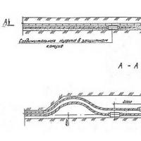 Requirements and rates for cable laying in Earth Scope of application, Definitions
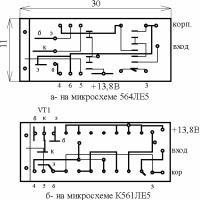 Automobile stroboscope from laser pointer
 Order 20 UAH to the account. How to Borrow on MTS. Additional information on the service
 How to check the account replenishment
 How to get a loan on tele2?
 Responsiveness SSD on a miniature board What SSD Drive Buy