How does the ignition contact system work? Contact ignition systems, device, principle of operation Purpose Device and operation of the contact system ignition
The engine ignition system is needed for reproduction of high-value currents and distributing it on contact candles of fuel ignition. Taking into account the change in the crankshaft revolutions and the load on the motor pulse of high-voltage voltage is applied to the candles at a given period. Nowadays, cars are equipped with contact and contactless inflammation systems.
Contact Ignition Contact System
Low-voltage currents serve as a power source and proceed from the generator and car battery.
As a rule, the value of such a voltage is equal to twelve-fourteen volts. And to reproduce the moment of the spark in the candlelight, we need to file to twenty thousand volts on them. Given this factor, the inflammation system has two different electrical circuits in its design. The ignition system scheme is assembled from the following devices and elements: battery, coils, traver, fascination lifting regulators of vacuum and centrifugal types, contact candles, electrical conductors, locking device.
Separate system elements
To convert low voltage currents to high in the design, the installation of the ignition coil device is provided. It is located in the open space, as well as most of the elements and the mechanisms of ignition. The main way of work is as follows: the windings of the winding are not high with high voltage pass, and at this moment the magnetic field is converted near the winding. In the event that stop the voltage supply in the turns, the disappeared magnetic field excites currents directly in high voltage twists. The process of converting twelve volts in twenty thousand occurs due to the difference in turns in the windings of coils. It is such a high voltage indicator that is necessary for the formation of a spark between the contacts of the candles.
Work of the breaker
The correct operation of the ignition system is impossible without such a mechanism as the current voltage interrupter of no high indicators. Its work is to interrupt currents in low voltage windings. This, in turn, contributes to the formation of high voltage.

The current is sent to the main contact, located under the lid of the dispenser device. The flexible spring of mobile contact all the time presses it to a stationary element, and they only diverge for a short period of time. This happens at the moment when the cutter of the drive mechanism of the interrupter affects the hammer of mobile contact.
Capacitor
To exclude the fact of burning contacts at the time of their opening, the condenser is connected to them in parallel. During the divergence of contacts of the dispenser's mechanism between cams, sparking is possible. In this case, the condenser serves to absorb most of the electricity and reduces the possibility of forming a spark to a minimum. Additionally, it accompanies an increase in the voltage in the secondary coil windings. At the time of the interrupter's contacts, the condensing device gives its current and thus creates inverse currents in the low voltage circuit. This contributes to the acceleration of the disappearance of magnetic fields. And the sooner it happens, the higher the currents in the high voltage line will be. In the case when the traver capacitor fails, the motor will also not start and operate. The voltage parameters of the turns will be too small for the occurrence of optimal sparking. The spark between the candle electrodes will be "poor", and this is not enough to ignite the fuel mixture. Low current interrupter contacts and high voltage distributor are installed in the housing of the traver and are powered by the crankshaft of the motor.
Lid traver
Distribution of high voltage on the cylinder candles of the power unit is carried out due to the distribution cover of the traver. After formation in the coil of high indicators, they enroll on the main contact of the interrupter dispenser, and then, through the moving element, on the rotor plate. At the time when the rotor rotates, the voltage slips from the plate to the contacts cover contacts.

Then, the short pulses of high voltage circuiters come directly to the contacts of the distribution cover have a specific numerology, which corresponds to a specific engine cylinder.
This is exactly the moment of operation of the cylinders. A certain order of work provides for a uniform distribution of the load on the crankshaft. Mostly four-cylinder engines have the following work order: 1-3-4-2. But it can be insignificantly changed depending on the manufacturer. In this case, the formula of the order of work means that initially ignition occurs in the first cylinder, then in the third, fourth and second. At the same time, the engine ignition system provides for supplying the voltage to the candle at the end of the compression tact. This is due to the installation
Ahead of the moment of sparking is necessary due to the high speed of moving the pistons in the cylinders. In the event that the fuel mixture will flamm a little later or earlier, the efficiency coefficient of expanding gases will significantly decrease. Therefore, fuel ignition should be carried out at a specified moment when the piston is suitable for NTC. With a properly installed angle of advance, the optimal amount of gases required for normal operation of the engine will affect the piston. The advance angle is exhibited by turning the chassis of the interrupter. This is how a certain point is selected when the contacts of the interrupter are bred.
Centrifugal regulator
The centrifugal regulator provides the installation of the correct angle of fooling, depending on the rotor of the engine. The design of the regulator mechanism is a pair of cargo that rotates, affect the plate with the interrupter contacts.
Vacuum regulator
Depending on the degree of load on the engine, the moment of formation is adjusted by a vacuum regulator. This device is mounted on the housing of the traver. The vacuum controller consists of two cameras separated by a diaphragm. One chamber interacts with the atmosphere, and the second with a pipe with a choke container. Using the rod, the diaphragm has a compound with a plate, which is equipped with interrupter contacts.
With an increase in the angle of rotation of the throttle, there is a decrease in the discharge in the choke cavity. In this case, the diaphragm moves the plate for a slight angle together with the contacts towards the cam cutter cam. Based on this, the opening occurs with the delay, and, accordingly, the angle changes.
Sparking Candles (Contact Ignition System)
The ignition system is equipped with standard elements overlap. The contact elements of sparking are needed to convert electrical energy to the spark, to ignite the fuel mixture in the engine cylinders. At that time, when the electrical pulse is transferred to the candles, its contacts contribute to the formation of a spark breakdown. This item is an integral element of the ignition system.
Bronvert
The ignition system is the contact, the ignition system of other types in its set has equipment to be equipped with armorpers, which may be carried out without damage and losses to skip the high voltage voltage. In particular, this is an electric flexible wire, with one copper residential and multilayer insulation.

In this case, the contact wire is made in the form of a helix, which eliminates the radio interference. As a rule, the data of the wires are installed on the candles. With prolonged use, the insulation of wires can purchase microcracks through which the losses of high values \u200b\u200bare possible.
Faults of the ignition system and their elimination
The first and most common breakdown may be the absence of sparks on candles. The causes of such a malfunction can serve as the following points:
- Cramping electrical wires in the low voltage chain or the oxidation of their connecting contacts.
- Fitting the contacts of the distributor and their inclusion.
- The failure of the coil, the cutting of the capacitor, the defects of the distributor cover, damage to the armored wires and the candles themselves.
- Excessive moisture in devices.
Troubleshooting is possible as follows:
- Check by the measuring instrument of the entire chain and wiring.
- Cleaning the contacts of the traver from Nagara and adjustment of the gap.
- Replacing the faulty and suspicious state of the system details.
It happens that when the ignition key turns, the starter does not work, and all the systems are working visually, in which case it is necessary to pay attention to the fuse unit, since it is possible to break or oxidizing the seat of the fuse that is responsible for turning on the starter.
If the car engine works unstable and does not develop full power, then the reasons can be as follows:
- The failure of one of the spark plugs.
- Too big or, on the contrary, a small gap on the candlelight and contacts of the distributor.
- Mechanical damage to the rotor or lid of the traver.
- The advance angle is incorrectly installed.
Repair is as follows:
- Installing new details.
- Adjust the required gaps.
- Adjusting the angle of spar formation.
The control system of the ignition system is quite simple and widely used on various cars.

With the use of new technologies of ignition elements, cars are constantly improved and modified. For example, newer models of various manufacturers have long used electronic ignition systems. When problems appear in the system, you can easily determine the reason for their occurrence and repair. The contact system of the VAZ car ignition system has no fundamental differences from the elements of other manufacturers and has high operational reliability. At the same time inexpensive in repair.
Contact transistor system
Compared to a conventional contact system, the contact-transistor has a transistor in its equipping. Its use contributes to improving performance and indicators. With the installation of the transistor, the system began to equip the switch.
The device of the contact-transistor ignition system is not very different from the usual ignition and its principle of operation. But still she has some minor differences.
Its main distinguishing feature is the possibility of the impact of the interrupter on the device of the transistor, and not to wind the coil. During the interruption of currents in the low voltage winding in the turns of high voltage winding occurs its formation.
Contact ignition system (vase including) has a number of positive characteristics.

Process management that is inherent in the ignition coil contributes to the possibility of increasing current values \u200b\u200bin the primary vita winding, and as a result, it is possible:
- Increase the values \u200b\u200bof the secondary voltage.
- Increase gaps between candle electrodes.
- Improvement and more stable moment of sparking.
- Facilitate the launch of the motor in the cold season.
- Increase engine speed and power.
A similar contact-transistor ignition system provides for connecting a coil with a separate primary and secondary windings.
In this case, this system reduces the load on the interrupter's contacts and reduces the risk of their burning. This is possible due to a decrease in current currents. Thanks to this fact, the degree of reliability and durability of the entire system increases.
The following can be attributed to the disadvantages of such ignition: the voltage of currents entering the transistor has a significant impact on its work. A decrease in current readings associated with the condition of the interrupter's contacts strongly affects the operational indicators of contact transistor ignition. The malfunction of the ignition system of this type is identical to the malfunctions of the conventional contact system and are eliminated in the same way. But additionally, problems can occur with a violation of the normal operation of the transistor and switch.
Engine start system
Starting the engine can not be carried out without additional electronic devices. In this context, it will be about such a mechanism as a car starter. This mechanism is an electric motor that leads to the initial movement of the crankshaft of the motor until the ignition in the cylinders and the start of the engine. The starter is turned on by turning the key in the lock to the appropriate position. Currents through the ignition relays come from the battery to the starter coats and drive it into action.
If we consider in detail, the engine start process is performed in three stages:
- The retractor mechanism of the starter launches the gear gear with the crown of the flywheel.
- Next, the starter rotor rotates together with the drive gear, and the one, in turn, transmits the torque on the crankshaft, which leads to the launch of the power unit.
- After the engine starts, and the ignition key returns to its original position, the pulling mechanism displays the starter drive gear from the engagement with the flywheel.
Purpose of relay
Any electrical relay is a safety device that is equipped with the ignition system. Contact ignition system in this regard is also no exception. Its main purpose is the opening and closure of a variety of sections in the electrical circuits of the car. Devices have differences in the design and method of the control signal, as well as installation. At the moment, widespread use received
Speaking with simple words, this type of electrical equipment auto protects various elements from high current loads. Simply it serves as a switch. In particular, in the ignition system, the relay protects the starter of the car and the generator from exposure to high currents. For example, to start the engine you need to turn on and enable the starter to work, which, in turn, consumes from 80 to 300a.

In this case, if you do not use the relay, the lock can burn, as well as some elements of the wiring. In order not to have happened, the ignition relay is included. When there is an image of a diode icon on the device, it means that when it is connected, it is important to observe the polarity of the terminals. Otherwise, breakdown is inevitable.
Conclusion
As a result, it is worth noting that the first, widespread in the automotive market, was the ignition system contact. This ignition system was used quite confidently, but at the moment it is considered morally obsolete. Its weakest place is just the presence of a contact pair in the design of the traver. After all, it required periodic service that cooked to the need for checking and adjusting the gap between the contacts, cleaning the surface of the contacts from various kinds of burning traces, which could significantly affect the performance of the elements as a whole. A non-contact, which does not require such service work and is characterized by motorists as more reliable.
So, we found out what kind of performance principle is a contact-transistor car ignition system.
Contact ignition system - The oldest one in modern cars will not meet it. Sometimes it can be found in the old models of cars. For example, VAZ used the ignition contact system in its vehicles up to 2000. In the Ignition Contact System, the detonation of the air-fuel mixture occurs with a spark resulting from the supply of high voltage current to the spark plug electrodes.
Contact ignition system
The first car, which uses the contact battery system of the ignition was Cadillac 1910. The innovation was well received by motorists. From this point on, the era of contact ignition began. Contact transistor ignition system She became the next step in the history of the automotive industry. Modern machines use non-contact, electronic ignition. It is more reliable and safe.
The contact system of internal combustion engines consists of:
- Power source;
- Interrupter-distributor ignition;
- Ignition coils;
- Low and high current wires;
- Spark plug;
Double ignition coil winding conducts current. The wire on the primary winding conducts a low voltage current, which, when switching to the secondary winding, is converted to a high voltage current. The essence of the ignition process: from the coil to the electrodes of the candle, with the participation of the mechanical distributor, a pulse is supplied, which flames the air-fuel mixture.
Contact Ignition Contact System
The distributor consists of a lid and rotor. On the lid there are two groups of contacts that carry out voltage distribution. The central group of contacts comes the pulse from the secondary winding, and through the side voltage is fed to the candle.
The distributor is one of the main parts of the traver. The second component of the traver is a breaker that operates the current circuits on the coil windings. The rubber is activated using the engine crankshaft.
The magnitude of the ignition occurs until the top of the dead point is reached. This is done so that the burnout of the air-fuel mixture occurred as efficiently as possible and in full. The angle of rotation of the crankshaft, in which the moment of ignition occurs - the ignition advance angle.
It may vary depending on the degree of load on the engine. The vacuum advance controller is designed to determine the necessary ignition angle.
To transfer the pulse from the ignition coil, and then - to the candle, use high-voltage wires.
How is the ignition process?
The key rotates, the starter is turned on. The current coming on the primary winding of the coil, when opening the circuit, is converted to a high voltage current. When operating the chain on the secondary winding, the pulse enters the distributor, which redirects it to the spark plug electrodes. A spark occurs, with the help of which the detonation of the air-fuel mixture occurs.
Brokes of the Contact Ignition System
What signals the problems with the internal combustion engine ignition control system?
With reasonable operation, the contact system of ignition will not deliver trouble and will last long time, not recalling himself. In order for the system to work without failures, you must be able to diagnose some faults.
- There is no spark. Such a failure in the operation of the system may occur when the wires are cut, burn the contacts, the ignition coil malfunction, during the candle breakdown.
- The engine works with failures or does not reach full power in operation. Such a scenario is possible when "moved" contacts, there is a breakdown in the rotor or a defective spark plug.
To eliminate or prevent such damage, it is necessary to follow the purity and integrity of contacts, fixing the wires. If one or another detail failed, it must be replaced.
The engine can be sewn due to uneven operation of the ignition candles. Candle electrodes can often burn, so fails arise. Clear electrodes can be at home. To do this, they must be cleaned with nadfil, and if the electrodes are very burned, the candle will have to be replaced. About the state of the candle says the color of the electrodes. In a good candle, it is light brown, in non-working electrodes burnt to black.
Another problem node of the system - high voltage wires. Often they "depart" from the electrodes, as a result of which contact disappears and the engine does not start. In addition, the situation often arises when instead of igniting the air-fuel mixture, the current goes to the side. To solve problems with wires, it is recommended to acquire silicone wires through which the current does not go.
Simple recommendation - Do not climb the hood of the car during the rain or heavy snow, and also do not ride deep puddles. If water falls under the hood, electrical parts of the car control systems can be flooded. Went electronic details will not work. Therefore, the machine can stumble, but the driver can continue the path only when all the details are dried.
Breakdown of contactless ignition system
In the contactless ignition system, similar problems arise, the engine begins to collect, stalls, will not start. The bulk of problems is associated with the contamination of parts. In winter, there are moisture and salt in the spare parts, which the roads are sprinkled, in the summer - dust that penetrates all the gaps.
The machine start system, like any part of a single system, provides comfortable use and uninterrupted operation of all nodes. Competent operation, timely diagnosis, high-quality repair will help all car mechanisms serve for a long time and work without breakdowns.
Introduction.............................................................................................................................. 3
Contact ignition system.......................................................................... 7
Starter...................................................................................................................... 15
Basic malfunctions of the battery system
ignition and its maintenance............................................. 18
Repair and maintenance of the starter......................................... 21
1 - distributor sensor; 2 - Ignition Candle; 3 - electronic switch; 4 - rechargeable battery; 5 - general torus; 6 - ignition coil; 7 and 11 - wires of respectively low and high voltage; 8 - Mounting block; 9 - ignition switch; 10 - switch sensor plug connector; + B - plus ignition coil terminal
The electron-mechanical device of the distributor sensor when the ignition is turned on and the engine running produces voltage pulses to the electronic switch, which converts them to intermittent current pulses in the primary winding of the ignition coil. At the time of interruption of the current pulse in the primary winding in the secondary winding, a high voltage current is indispensable. The high voltage current from the ignition coil on the wire is supplied to the central terminal of the distributor cover and then through the coal contact, the rotor coal plate, the side terminals are fed to the spark plug and the spark discharge flames the working mixture in the engine cylinders.
Advantages of the contactless ignition system:
Improving reliability due to the lack of mobile contacts and the need for systematic stripping and adjustment of gaps;
Lack of influence of vibration and beating of the rotor-distributor to the uniformity of the moment of sparking;
Improving the reliability of the start and operation of the engine during the acceleration of the car due to the higher electrical discharge energy, which ensures reliable ignition of the working mixture in the engine cylinders, regardless of the rotation frequency of the crankshaft;
Simplification of the maintenance of the ignition system.
This paper discusses the engine start system, which includes: Contact ignition system, starter and maintenance.
Contact ignition system.
A compressed working mixture in the engine cylinder is ignited by an electrical discharge - spark, which is generated between the spark plug electrodes.
To form an electric discharge in a compressed working mixture, a voltage is needed at least 12-16 square meters.
Converting the low voltage current in high voltage current and the distribution of its engine cylinders is carried out by battery ignition devices. The battery ignition system consists of low voltage current, ignition coil, distributor interrupter, capacitor, ignition candles, ignition switch and low and high voltage wiring (Fig. 4). In the battery ignition system there are two chains - low and high voltage.

Fig. 5. Ignition coil |
 0.8 mm, cardboard tube, secondary winding of 19 ... 25 thousand turns of thin wire with a diameter of 0.1 mm, iron housing with magnetic pipelines, carbolite lid, terminals and an additional resistor.

Fig. 7. Condenser
The secondary winding is located under the primary and separated from it the insulation layer. The ends of the primary winding are removed on the terminals of the carbic lid. One end of the secondary winding is connected to the primary winding, and the second is removed to the central terminal of the carbic lid.
The core is made of separate transformer steel bars from separate isolated each other to reduce the formation of vortex currents. The lower end of the core is installed in a porcelain insulator. Inside the ignition coil is filled with transformer oil.
The added resistor consists of a spiral, ceramic sockets and two tires. Resistance ranges from 0.7 to 20 ohms. One end of the resistor is connected by a tire with a terminal VK, and the other - with WCB.
With a small frequency of rotation of the engine of the engine, the interrupter's contacts are for a long time in a closed state, the current power in the primary chain increases, the resistor is heated, the resistance in the chain increases, the current of a small force comes into the ignition coil, which it is protected from overheating.
When the engine speed of the crankshaft increases, the time of the closed state of the contacts decreases, the current strength in the primary chain decreases, the heating and resistance of the added resistor decreases, which prevents the reduction in the voltage in the secondary chain.
When the starter is turned on, the resistor is captured and the engine start is facilitated.
Interrupter-distributor . The formation of high voltage current and the distribution of its engine cylinders for timely ignition of the working mixture should correspond to the order of operation of the cylinders.
To induce the high voltage current in the secondary winding of the ignition coil, it is necessary to periodically erode the primary battery ignition circuit that
and performs a breaker. To distribute the high voltage current over the cylinders, respectively, the order of operation of the engine is the distributor. Both of these devices are combined into one - the dispenser.
Breaker(Fig. 6) Mounted on the engine and drives from the camshaft. The main parts of the interrupter are the case, drive shaft. Movable disk (on which the insulated lever with a pin and a fixed counter with contact), a fixed disk, centrifugal and vacuum lead regulators, an octane-corrector and a cam with protrusions by the number of cylinders are placed. The cam is connected to the drive roller through the centrifugal regulator. The contacts of the interrupter are deposited with a refractory metal - tungsten. The interrupter lever is fixed on the disk hinged and its contact is pressed against the fixed contact of the spring. The rotating drive roller with cams presses the textolite protrusion of the interrupter lever and for one turn will open, and the spring comes the contacts as many times as there are protrusions on the cam.
The opening of the primary chain of the ignition coil causes the disappearance of the magnetic flux, which crosses not only the rear winding, and the primary, as a result of which the self-induccus current voltage 200 ... 300 V. This current, slowing the disappearance of the current in the primary chain, leads to a decrease in the EMF In the secondary chain. The self-induction current also leads to intensive sparks between the interrupter's contacts and their destruction. To prevent the harmful effects of self-induction, the condenser is used. CondensaPurincluded parallel to the interrupter contacts and at the time of the manifestation of self-induction EMF is charged, preventing sparking on contacts. In addition, the charged condenser, discharged in the opposite direction, leads to a rapid disappearance of the current in the primary chain, and consequently, the magnetic flux, due to which the voltage in the secondary chain rises. Condenser (Fig. 7) consists of lacquered paper on which a thin layer of zinc and tin is applied. This paper is a capacitor and rolled into a roll. To the ends of the roll sold out one flexible conductor. The roll will be wrapped with cable paper and saturated with oil. The capacitor is mounted on the housing outside or on the movable disk of the interrupter.
Capacity of the condenser 0.17 ... 0.2 μF. Capacitors made of metallized paper have the ability to self-end when the dielectric breakdown due to the filling of the hole with the oil.
A great impact on the work of the battery ignition has a gap between the interrupter's contacts. The normal operation of the battery ignition will be at the gap between the interrupter contacts within 0.35 ... 0.45 mm.
 If the gap is large, the time of the closed state of contacts will decrease and the current strength in the primary winding of the ignition coil will not have time to increase to the desired value and, as a result of this, the secondary chain will not be sufficient. In addition, with a high frequency of rotation of the crankshaft, interruptions will occur in the engine. With a small gap, there is a strong sparking between the contacts, their overtaking and, as a result, interruptions on all modes of engine operation. The gap between the interrupter contacts is regulated by moving the plate with a stationary contact with an eccentric, unscrew the pre-lock screw (Fig. 8). After adjusting the locking screw must be wrapped. Measure the gap with fully open contacts with a plate dipstick.
Div_adblock158 "\u003e
Select the ignition candles for the engine but their notation, where the diameter of the rifle part is indicated, the length of the lower part of the insulator and the material
 |
 |
insulator. The diameter of the rifle part is denoted by letters M and A, where M corresponds to the diameter of 18 mm and a - 14 mm. The digit is marked with a caliper. The length of the threaded part is denoted by the letters of H -11 mm, d - 19 mm. If there are no letters, then the length of the screw part is 12 mm. The letter "B" denotes that the lower part of the insulator protrudes, and "T" - that the sealing of the insulator is made by thermo cement.
On GAZ-53-12 and ZIL-130 cars, install Candles A11, where the letter A is indicating that the diameter of the thread 14 mm, the number 11 indicates a calil number, the length of the bridge of the housing is 12 mm. A great influence on the operation of the spark plug has a gap between the central and side electrodes. Plants recommended gaps of 0.85 ... 1..00 mm. Reducing the gap against the norm causes abundant on-line spark plug electrodes and interruptions in its work. With a greater gap due to increased resistance, spar formation conditions deteriorate, which will also have interruptions in the engine. Adjust the clearance by the bending of the side electrode, and its size is checked with a round dipstick (Fig. 9, B). The central electrode is not to bend, as ceramic insulation and the ignition candle refuses to work.
Ignition switch.Turning on and off the battery ignition devices and other electrical current consumers are carried out using the ignition switch. It consists of two parts: the lock with the key and the electrical switch. The lock consists of a housing, cylinder, springs and a leash. In the back of the lock case, there is a switch consisting of a contact plate with three protrusions and a panel with three contact screws.
In cars ZIL-130 and GAZ-53-12, the key has three positions: the first (the key is located vertically) - ignition is turned off; Second (turn of the key clockwise) - ignition is included; The third (rotation of the key to failure) - ignition and starter are included. In all cases, along with ignition, control and measuring instruments are included.
Starter.
A reliable engine start is possible provided if its crankshaft rotates with a frequency of 60 ... 80 min-1. Since the achievement of such a frequency of rotation with the help of a handle requires a considerable effort from the driver, then an electric motor is used to facilitate the driver's work when starter. The main parts of the starter (Fig. 10), as well as the generator, are: body, anchor with windings and a collector, two covers, brushes and brush holders.
Due to the consumption of the starter of the significant strength of the current (up to 900 a), the excitation winding and the anchors are made of thick wire. Four excitation winding sections are included in sequentially winding anchor with two parallel branches of two excitation windings in each. Brushes for better conductivity are made by copper. Two brushes are connected with a mass, and two - with the windings of the excitation. The brushes pinned in the brush holder are pressed to the collector springs. To bring the engine's crankshaft rotation, the starter is equipped with a drive connecting the starter shaft with a gear of the flywheel. The starter is included using the ignition switch. The operation of the starter is based on the interaction of magnetic fields of excitation and anchor windings when electric current is passed.
The starter drive must provide a starter gear connection with the flywheel's crown only for the start of the engine. After starting the starter shaft should be immediately disconnected, otherwise the weden of the flywheel will rotate the anchor of the starter with a very large frequency and the turns of the winding of the anchor can exit the groove under the centrifugal force.
On the cars studied, the starter with remote control and electromagnetic inclusion is used (Fig. 11). The drive consists of a switching relay, a traction relay with two windings - retracting and holding, lever with a fork, rings, springs, a slotted sleeve and couplings. The retractor winding is enabled sequentially winding anchor, and retaining - in parallel.
The coupling of the free move consists (Fig. 10 b, B, g) from the leading clip moving on the splitting of the shaft, and the slave closet with gears and four wedge-shaped recesses. In wedge-shaped notches are placed rollers with springs. The rotation of the leading rope causes the movement of the rollers into a narrow part of the recess and the jamming of the slave clip on the master. If you rotate in the course of the slave on the leading, the rollers move into a wider part of the recess and the slave of the clip will rotate freely on the lead.
 To turn on the starter, you must rotate the ignition key to the right to failure, while the inclusion relay winding circuit is closed.
The magnetic field created by winding the relay leads to a closer to the relay contacts, as a result, the pulling and holding winding of the traction relay is included in the electrical circuit. Under the action of the magnetic field of the windings, the core of a traction relay and a lever associated with it is drawn, introduces the drive gear with the flywheel's crown. At the same time, the copper contact disk on the other end of the rod after the gear is turned on will be closed by the starter power circuit.
When turning the ignition key to the original position, the holding circuit of the holding winding is blocked, and the core of the traction relay, and with it the lever and the copper disc will return to its original position, the starter will turn off.
On the car KAMAZ, the starter applies a drive with a ratchet mechanism of free stroke. The drive moves along the slots of the anchor shaft. It consists of a housing, a leading and driven semi-humus, springs, sleeves with spiral slots and a mechanism for centrifugal disconnection of a semi-humule. The starter should be included for a while no more than 5 s. If necessary, the starter can be turned on again with an interval of at least 0.5 minutes. This period of time is needed to restore the rechargeable battery performance. Turn on the starter is not more than 3 times in a row.
|

The main malfunctions of the instruments of the battery ignition system and its maintenance.
Malfunctions in the operation of battery ignition devices are detected by interruptions in the engine operation, difficult to start it and sharp cotton from the muffler.
If interruptions occur in different cylinders, this indicates a malfunction of the distributor of the distributor or the ignition coil. Interruptions in one cylinder occur in most cases due to the malfunction of the ignition candle or high voltage wires.
The disorder of the dispenser's interrupter can occur due to contamination or burning contacts, closing the lever to the mass, the gap disorders between the interrupter contacts, the condenser malfunction, cracks in the lid or the distributor rotor, the carbon brushes. In the ignition coil may be damaged isolation of windings.
Contaminated contacts are wiping with a rag moistened in gasoline, and burnt contacts are prefier or sandpaper. The disturbed clearance is restored by adjustment; The lever closing on the mass is wiped, inspecting and damaged insulation, the wiring is gently isolate. The cover or rotor of the distributor having cracks must be replaced. The broken coal brush is also replaced, and polluted is cleaned.
The condenser malfunction is detected by strong spark between the interrupter contacts and the sharp cotton in the muffler. The condition of the capacitor is verified in the following ways:
the high voltage wire from the ignition coil is set at a distance of 6-7 mM.from any metal parts of the engine and after switching on the ignition, contacts are broken - the intensive spark between the tip of the wire and the mass indicates the health of the condenser;
receive the wire, the capacitor from the terminal and, turning on the ignition, open 1-2 times the contacts; At the same time, a strong spark arises between them.
If, after connecting the capacitor wire, the spark will remain the same, then the condenser is faulty, a weak barely noticeable spark between the contacts testifies to the health of the condenser. The condition or usefulness of the capacitor is more accurately determined on the stand.
Most often, the ignition coil refuses if the ignition is left included for a long period of time with closed contacts of the interrupter. The ignition coil windings are heated, the insulation is melted and the short circuit of turns occurs. At the same time, the addition resistance can also burn. Faulty ignition coil is not necessary to replace.
Faulty spark plug can be detected by alternate disconnection of the high voltage wire from the candle. If the reconnected candle is properly, then the interruptions in the engine work increase. When the defective Ignition Candle is disconnected in the engine operation will remain unchanged.
To eliminate malfunction, the ignition candle must be turned and inspect if there is a nagar deposition on it, it must be cleaned, rinse with gasoline and bleed with compressed air. The gap between the electrodes is checked and, if necessary, adjust the side electrode with a spark plug having a cracked insulator, must be replaced.
The secondary battery ignition circuit is checked when the ignition is turned on and closed the interrupter contacts. The high voltage wire of the ignition coil is set for a distance of 4-5 mM.from any metal parts of the engine and hand blur the contacts of the interrupter; The intense spark between the wire and the engine part indicates the serviceability of the instruments. The presence of a current in the low voltage circuit is checked with a lamp included parallel to the interrupter contacts. The lamp should be burned when the ignition is turned on and open contacts of the interrupter.
Maintenance. Lubricate the interrupter interrupter with a grease of a grease through a cap oil, clean the dust of dirt and oil the surface of the battery ignition devices, check the spark plugs and, if necessary, clean them from the car, check and adjust the gaps between the candles' electrodes, remove the interrupter, clean and check the condition Contacts and gap between them. If necessary, adjust, gap, lubricate the shaft, cam, interrupter interrupter cam and axis of the rolling contact lever. The cam is lubricated from the felt wick, wetting 1-2 drops of liquid oil used for the engine. The fist sleeve is lubricated with 1-2 drops of liquid oil with a felt washer shot, check the condition of high and low voltage wiring.
During the inspection of the battery ignition devices, contact with the bare parts of high voltage wiring.
Repair and maintenance of the starter.
Starter malfunctions. The main starter malfunctions include weakening the fastening of the supply wires, wear or contamination of the brushes and the collector, the oxidation of the switch contacts, break or closure in the windings, wear the parts of the free stroke clutch and the gear clutch. These faults lead to the fact that the starter does not work at all, does not develop the desired speed and power, when turning on the anchor of the starter rotates, and the crankshaft is fixed, a strong noise is created when the starter is turned on.
When turned on, the starter does not work at all,the characteristic clicks of the traction relay is not auditioned. To identify reasons, you need to turn on the headlights and starter. If, when the starter is turned on, the lamps will not change, it indicates a bad contact or a break in the chains of the auxiliary relay either in the main operating current circuit.
If the lamps are highly reduced, then the likely cause can be a poor state of the battery or a contact disruption in its terminal connections, as well as the starter motor malfunction. Places of bad contact in electrical circuits and cliff are determined by the sequential connection of the control lamp in the specified electrical circuits. If necessary, you need to check the degree of charges of the battery. If, when you turn on the starter, characteristic clicks are listed, this means that the trailer relay is properly.
When turning on the starter crankshaftit is very slow.The most frequent causes of this are the insufficient charge of the battery, oxidation and (or) attenuating the attachment of the contacts of the working electrical circuit of the starter or slip (turning) the roller clutch of the free stroke. With a good rechargeable battery, the starter must be removed to verify and troubleshoot.
When the starter is turned on, the anchor rotates, and the flywheel is notmove.The causes of this malfunction can be a slip of the free-running clutch, an axis loss or breakage of the coupling lever, breakage of the leashed ring of the coupling or buffer spring.
Strong noise when turning on and starter operationit is possible when weakening its fastening, the breaking of the holding winding of the retractor relay, breakage of the gear gear and the wint of the flywheel.
Strong noise after starting the enginemeans the starter does not turn off. You need to quickly drown the engine, turn off the battery, check the starter attachment, and if necessary, remove it and check the condition of the drive gear gear and the winding of the retractor relay (closure).
Starter repair includes testing performance on the stand, disassembly, checking parts and assembly.
Check starterit is performed on a special stand in idle mode and under load. The electrical starter switching circuit when checking is shown in Fig. 12. Connecting wires to the battery and the ammeter must have a cross section of at least 16 mm2. When the voltage is summed 12, the starter must end the current within 70 ... 85 A (depending on the model), and the speed of the anchor should be within 5000 + 500 min -1.
Increased current consumed, reduced speed, as well as noise during operation indicate electrical or mechanical faults. The reduced current consumed and the reduced speed of the anchor rotation during normal voltage on the starter terminals indicate a violation of the contacts in the wires of the wires or in the brush node (wear, sealing brushes, collector contamination). To test the starter under load in full braking mode on the drive gear, a clamping device with a lever connected to a dynamometer, and determine the braking point. This is done short-term (no more than 4-5 seconds, so as not to overload and damage the starter winding) the inclusion of the starter and the measurement of the effort developing on the Dynamometer scale. Upon multiplication of the measured dynamometer, the magnitude of the length of the lever shoulder determine the torque developed by the starter, which must correspond to the passport data of the starter.
 |
Disassembly of the starterit is performed in the following order:
· Disconnect from the retractor relay (see Fig. 12) output of the excitation coil and remove it by disconnecting from the cover;
· Remove the tie bolts (at the VAZ-2109 car starter, after removing the casing), remove the cover with the brushes and remove the brushes from the collector side holders;
· Disconnect the housing with the front cover and remove the anchor assembled with the coupling of the free move;
· Remove the clutch of the free move, for which it is necessary to move the restrictive ring towards the drive and remove the speaker ring from the valve.
After disassembly, all parts should be rinsed and bleed with compressed air and check them.
Checking starter details on closureit is performed using the indicator and power source or autotester, as shown in Fig. 13. When a closure is detected on the light of the indicator lamp, the defective part is replaced.
Anchor of the starter should not have mechanical damage to slots and increased collector wear. With significant roughness and depreciation of the collector, it is pulled and cleaned with a fine-grained grinding skin.
Closed excitation coils can be replaced by unscrewing with a press screwdriver screws for their mounting to the starter case. When the screws are wrapped in assembly, their heads are boosted to avoid spontaneous turning.
The coupling of the free move is checked to turn her gear on the hub: the gear should be freely turning relative to the hub in one direction and not to turn to the other side. The gear teeth should not have traces of painting and chipping. Small fears on the root part of the gear can be removed by grinding fine-grained grinding circle.
The starter caps should not have chips and cracks, the worn sleeves of the anchor shaft are recresented.
Brushes must move freely in the belt holders and with increased wear, they must be replaced. The height of the brushes should be at least 9 mm at the starter of the ZAZ-1102 car and at least 12 mm - at the starters of the rest of the passenger cars.
Assembling starterit is carried out in the order of reverse disassembly. The screw slots of the armature shaft when assembling it is necessary to lubricate by engine oil, and the sleeve sleeve and the drive gear - Litol-24 lubrication. When assembling, the axial movement of the anchor shaft is adjusted by the selection of quantities and the thickness of the adjusting washers installed on the front or rear (depending on the starter design) of the shaft of the anchor. After the assembly, the correctness of the drive adjustment is checked in the distance between the end of the gear of the free stroke clutch and the restrictive ring of its stroke.
Starter maintenance It lies in the periodic lift of the fumes of the wires and the cleaning of the outer surfaces from pollution.
 To ensure reliable operation of the starter, it is recommended through every mileage, and if necessary, before, removing it from the car to clean and check the state of its parts and lubrication. At the same time, the manifold is cleaned and, if necessary, replacing worn brushes, as well as adjusting the drive and axial movement of the anchor shaft.
General labor safety requirements for maintenance and repair of cars, production sanitation and fire fighting events
Creating safe working conditions There must be defdividing in any field of production activitiesman. And even more so, where work is associated with increasedhuman health hazard.
There is a state system in Russia.tov safety of labor establishing general safety requirements (GOST 12.3.017-85), which are carried out on motor transport enterprises, stations of other specialized centers with all types of maintenance (MA) and current repair (TR) of cargo and passenger cars, buses, tractor, trailers and semi-trailers (hereinafter - cars) intended for operation on the roads of the total network of Russia.
Ensuring safe working conditions leaddenia Prosecutor's Office, State Banking, Gorthernadzor, Firenaya inspection and other state control services.Responsibility for the fulfillment of the total volume of tasksthe building of safe working conditions is entrusted withmotor transportation enterpriseengineer.
All persons entering work undergo introductory safety instructions and industrial safetynitara, which is the first stage of teachingsecurity at this enterprise. The second stage of the traininvestment is instructed in the workplacein order to assimage the working safe techniques of labormiddle for the specialty and in the workplace where it should work. When performing work raiseddangers are held repeated briefings throughcertain intervals, but at least oncein 3 months.
Additional (unscheduled) instructionconductin violation of working rules and instructions for thosesecurity, technological and production distsiplin, as well as when changing the technological processca, type of work and type of car service. All speciesbriefings are recorded in special magazines, whichrye are stored at the head of the enterprise, workshops or productionwater plot.
Production sanitation. An important condition for safe and high-performance work is to eliminate the impact of production.harmfulness: air pollution; noise and vibrations; abnormal thermal regime (draft, low or high temperature in workplaces).
Under the influence of production intories canthere are professional diseases.
The task of industrial sanitation and health hygiene yavthere is a complete exception or a significant reductionproduction harm. Rooms Autotransportthere should be equipped with centralized or autonomous heating, air-free ventilation, sanitary and domestic, shower, wardrobe, washbasins, toilets, rooms equipped for meals, and smoking rooms.
Fire events. For the premises of motor transport enterprises and car service services, a high fire hazard is characterized. Notcreate conditions for the emergence of a fire in industrial premises and by car, prohibited:mAKING TO MINE AND PROCESS TOPliva and oils; Leave in the cabin (salon), on the engine and workplaces of unforgettable materials; allow to flow in fuel lines, tanks and nutritional instruments; keep open neck fuel tanks and flammable liquids; wash or wipe the body of the body, details and aggregates, wash your hands and clothes with gasoline; Store fuel (with the exception of the car in the fuel tank) and the container from under fuel and lubricants; use open fire while troubleshooting; Heat the engine open fire.
All passages, passages, stairs and recreation Avtransports enterprises should be free to passand travel. Attic can not be used under productionstorage facilities.
Smoking on site and in production placingthe vehicle is allowed only in the allocated places equipped with fire fighting and the inscription "Smoking Space". In prominent placesnear telephone sets should be posted signs with indication of fire team phones, the evacuation plan of people, cars and equipment in case of fire and the surname of persons responsible for fire safety.
Fire cranes in all rooms equip handyou and trunks enclosed in special cabinets. INpremises for maintenance and repair of motor vehicles Install foam fire extinguishesteli (one fire extinguisher at 50 m2 of the area of \u200b\u200bthe room) anddrawers with dry sand (one box per 100 m2 area of \u200b\u200bthe room). Near the sandbox on the fire station mustspade, scrap, Bagg, ax, fire bucket.
Timely lighting and fast litterthe fire team is the main condition for the successful fight against the emerging fire.
Literature.
1. Kalisky (third-class driver textbook), Nag0 g., 384c.
2. Carovel. Device, maintenance and repair of cars: ed. 5th. Tutorial. / Gerasimenko A. I., R / D Ruisanov: Phoenix, 2004. - 576 p. (Series "Primary Vocational Education».)
The car motor in the first of its first modifications was a complex design consisting of a number of systems operating together. One of the main components of any gasoline engine is the ignition system. About its device, varieties and features we will talk today.
Ignition system
The car ignition system is a complex of devices and devices that work to ensure the timely appearance of an electrical discharge that flammifies the mixture in the cylinder. It is an integral part of electronic equipment and most of the mechanical components of the engine are tied at work. This process is inherent in all motors that are not used for ignition strongly heated air (diesel, compression carburetor). Spark ignition of the mixture is also used in hybrid motors operating on gasoline and gas.
The principle of operation of the ignition system depends on its type, but if you generalize it, the following steps can be distinguished:
- the accumulation process of high-voltage pulse;
- passage pass through an increase in transformer;
- synchronization and distribution of pulse;
- the emergence of sparks on the contacts of the candle;
- arson of the fuel mixture.
An important parameter is the angle or ahead of the advance - this time in which the arson of the air-fuel mixture is carried out. The selection of the moment happens so that the limit pressure occurs when the piston gets into the upper point. In the case of mechanical systems, it will have to be arranged manually, and in electronic-controlled systems, the setting is automatically. The optimal advance angle is influenced by the speed of movement, the quality of gasoline, the composition of the mixture and other parameters.
Classification of ignition systems
Based on the ignition synchronization method, the contact and contactless schemes differ. According to the Ignition Angle Angle, you can select systems with mechanical adjustment and fully automatic or electronic.
Based on the type of charge accumulation, for the breakdown of the spark gap, we consider devices with accumulation in inductance and with accumulation in the container. According to the switching method of the primary chain of the coil - mechanical, thyristor and transistor varieties.
Ignition systems nodes
All existing types of ignition systems differ in the method of creating a control pulse, the rest of them is practically no different. Therefore, you can specify common elements that are an integral part of any variation of the system.
Power - primary, is the battery (activated when started), and when working, the voltage that the generator produces is operated.
The switch is a device that is necessary to supply the power to the entire system or shutdown it. The switch is the ignition lock or control unit.
Charged charge is an element necessary for the concentration of energy in the desired volume, to ignite the mixture. There are two types of components for accumulation:
- Inductive - the coil, inside which is located a boost transformer which creates a sufficient impulse for high-quality arson. The primary winding of the device is powered by the plus of the battery and comes through the interrupter to its minus. When operating the primary contour, the interrupter on the secondary is created a high-voltage charge, which is transmitted to the candle.
- Capacitive - capacitor, which is charged with increased voltage. At the right time, the accumulated charge on the signal is transmitted to the coil.

Working diagram depending on the type of energy accumulation
Candles - a product consisting of an insulator (candle base), a contact output for connecting a high-voltage wire, a metal rim for fastening the part and two electrodes, between which the spark is formed.
The distribution system is a subsystem intended for the direction of the spark on the desired cylinder. Consists of several components:
- The distributor or rubber is a device that compares the crankshaft revolutions and, accordingly, the working position of cylinders with a cam mechanism. The component may be mechanical or electronic. The first - transmits the rotation of the motor and through a special runner distributes the voltage from the drive. The second (static) eliminates the presence of rotating parts, the distribution occurs due to the operation of the control unit.
- Switch - device generating coil charge pulses. The part joins the primary winding and breaks nutrition, generating self-induction voltage.
- Control unit - device on microprocessors, determining the moment of transmission of current to the coil based on sensor readings.
The wire is a single-liner high-voltage conductor in isolation connecting the coil with the distributor, as well as the contacts of the switch with candles.
Magneto
One of the first ignition systems is a magneto. It consists of a current generator that creates a discharge exclusively for sparking. A system of permanent magnet, which is driven by a crankshaft and inductance coils. A spark capable of breaking the spark gap generates an increase in the transformer, one part of which is a rough winding of inductance coil. To enhance the voltage, part of the generator winding is used, which is connected to the candle electrode.

Ignition system with magneto
Spark feed control can be a contact, made in the form of a breaker or non-contact. With a contactless method of filing Spark, condensers are used that improve the quality of the spark. Unlike the mining schemes presented below, the magneto does not require a battery, it is easy and actively used in compact technique - motocos, chainsaws, generators, etc.
Contact ignition system
Outdated, common flamm of fuel mixture. A distinctive feature of the system is to create high voltage, up to 30 thousand in candles. Creates such a high voltage coil, which is connected to the distribution mechanism. The pulse on the coil is transmitted due to the special wire connected to the contact group. When opening cams, the formation of discharge and sparks occur. The device also performs the role of a synchronizer, since the moment of formation sparks must coincide with the desired point of compression tact. This parameter is established by means of mechanical adjustment and spark shift to an earlier or late point.

Simple scheme
A vulnerable part of this option is a natural mechanical wear. Because of it, the moment of formation of the spark is changing, it is unstable for various positions of the slider. In view of which the vibrations of the motor appear, its dynamics falls, the uniformity of work is worse. Thin settings allow you to get rid of explicit faults, but the problem may arise again.
The advantage of contact ignition is its reliability. Even with a serious wear, the item will work trouble-free, allowing the motor to work. The scheme is not despicable to temperature modes, there is practically no moisture or water. This type of ignition is distributed on old cars and to this day is used on a number of serial models.
Contactless ignition
The schematic diagram of the contactless system is somewhat different. It saves a rubber as a design element, but it only performs the synchronization function of the cylinders and sends the pulse to the switch. In turn, the transistor element is synchronized with the sensor indicator and determines the ignition angle, as well as other settings - automatically.
The advantage of the system is the stability of the quality of sparking, which does not depend on the manual settings or the safety of the contact surface. If we consider the superiority of this option above the contact circuit, you can allocate:
- the system generates a spark of high quality constantly;
- the ignition system device eliminates the deterioration of its work due to wear or contamination;
- there is no need to produce fine adjustments of the ignition angle;
- you do not have to follow the status of contacts, control their closure angle and other settings.
As a result of using the contactless system, it is possible to observe a decrease in fuel consumption, improving dynamic characteristics, the absence of strong vibrations of the motor, a stable spark makes it easier to facilitate a cold start.
Electronic ignition
Modern, most perfect scheme, which completely eliminates the presence of moving parts. To obtain the necessary data on the position of the crankshaft and other are used special sensors. Next, the electronic control unit makes calculations and sends the corresponding pulses to the working components. This approach allows you to mostly determine the moment of the claim of the spark, thanks to which the mixture is incited in a timely manner. This allows you to get more power, improve the purge of the cylinder and reduce the harmful emissions, thanks to the best fuel oval.

Scheme of electronic system
The electronic ignition system of the car is characterized by high stability of work and is installed on most modern cars. Such popularity is determined by the advantages of this scheme:
- Reducing fuel consumption in all modes of motor operation.
- Improving dynamic indicators - response to gas pedal, overclocking speed, etc.
- More smooth operation of the motor.
- The schedule of moment and horsepower is leveling.
- Minimize power loss on low revs.
- Compatible with gas equipment.
- The programmable electronic unit allows you to adjust the engine to fuel savings or vice versa, to increase dynamic indicators.
The purpose of the ignition system is quite simple, it is an integral part of the gasoline engine, as well as motors equipped with HBO. This component is constantly changing and acquires new forms that meet modern requirements. Despite this, even the most simple ignition models are still used on various techniques, successfully performing their work, as well as dozens of years ago.
AUTOLEEK.Send your good work in the knowledge base is simple. Use the form below
Students, graduate students, young scientists who use the knowledge base in their studies and work will be very grateful to you.
Posted by http://www.allbest.ru/
Introduction
In the first engines (for example, the diver engine, as well as the so-called halfdouse), a mixture of fuel with air flammped at the end of the compression tact from a splitting glow head - a chamber communicating with the combustion chamber (synonym - a caliling tube). Before starting the calil head, it was necessary to warm up the solder lamp, then its temperature was maintained by combustion of fuel when the engine is operational. Currently, according to this principle, the glow engines used in various models (avia, auto-, shipyard) are operating. Calil ignition in this case wins with its simplicity and unsurpassed compactness.
Diesel engines also do not have the ignition system, the fuel is flammable at the end of the compression tact from the air heated in the air cylinders.
Do not need the ignition system compression carburetor engines, the fuel and air mixture flames from compression. These engines are also used in models.
But truly on gasoline engines passed a spark system, that is, the system, a distinctive feature of which is to ignite the mixture with an electric discharge, breaking the air gap between the spark plug electrodes.
Currently, there are three ignition systems: using magneto, battery ignition with a car battery and an ignition system without a battery using a motorcycle generator of AC.
It is possible to allocate: schemes without using radio-electronic components ("classic") and electronic.
In my graduation work, a classic ignition contact system is considered.
Contact ignition system is the oldest type of ignition system. Currently, this system is used on some models of domestic cars (so-called "classics"). Creating high voltage and distribution of its cylinders in this system occurs with the help of contacts.
1. Contact Ignition Contact System
1.1 Purpose of the Ignition Contact System
The ignition system is a combination of all devices and devices that ensure the appearance of an electrical spark that flames the fuel-air mixture in the internal combustion engine cylinders at the right moment. This system is part of the overall electrical equipment system. The ignition system is used to ignite the working mixture in the engine cylinders in strictly defined moments. Flammation of the mixture can be carried out by a battery ignition system or from magneto. On the car studied applies the battery system of ignition. By the method of interruption of the current circuit, the battery systems of ignition are divided into contact, contact transistor and non-contact transistor. Until 1960, on cars installed mainly the contact system of ignition. Currently, transistor ignition systems are increasingly used, especially in eight-cylinder engines.
1.2 Principle of the contact system of the ignition
Ignition system
The ignition system is used only in gasoline and gas engines. With its help, the fuel-air mixture that fell into the engine cylinders is set in price in a strictly defined point in time. The ignition of the mixture inside the cylinder occurs when the spark is formed between the electrodes of the ignition, when the current is supplied with a voltage of 18,000-20,000 V.
Three varieties of ignition systems are known:
· Contact,
· Contactless I.
· Microprocessor.
Contact system on modern cars does not apply. However, earlier it was widespread. Let us give it due, since she faithfully served for many years, and consider her principal device. The principle of operation is based on the law of electromagnetic induction. From the battery when the ignition is turned on and closed contacts of the low voltage, the low voltage current passes along the primary winding of the ignition coil, forming a magnetic field around it. The opening of the interrupter's contacts leads to the disappearance of the current in the primary winding and the magnetic field around it. The fading magnetic field induces high voltage in the secondary winding (about 20--25 kilovolt). The distributor alternately condes high voltage current to high-voltage wires and spark plugs, between the electrodes of which sparkles the spark charge, the fuel-air mixture in the engine cylinders is flammable.
The disappearing magnetic field crosses not only the rear, but also the primary winding, as a result of which the self-induccus current occurs with a voltage of about 250-300 volts. This leads to sparking and burning contacts, in addition, the interruption of the current in the primary winding is slowed down, which leads to a decrease in the voltage in the secondary winding. Therefore, in parallel, the condenser is connected to the interrupter contacts (as a rule, with a capacity of 0.25 microf).
A consistent primary winding of the ignition coil turns on the adding resistance (or an additional resistor). On low revs, the interrupter's contacts are most of the time in the closed state and flows through the winding, more than sufficient to saturate the magnet-wire. Excess current is useless heats up the coil. When the engine is started, the adding resistance is shunted by the contacts of the starter relay, thereby increasing the energy of the electrical spark on the ignition candle. Principle of operation of the contact system of ignition
With a closed interrupter contact, the low voltage current flows along the primary winding of the ignition coil. When opening the contacts in the secondary winding of the ignition coil is induced by a high voltage current. According to high voltage wires, the high voltage current is supplied to the distributor cover, on which it is distributed over the corresponding ignition candles with a certain ignition advance angle.
With an increase in the rotation of the crankshaft of the engine, the revolutions of the camshamber shaft are increasing. Georgs of the centrifugal regulator of the ignition protrusion under the action of centrifugal force diverge, moving the movable platinum with the cams of the interrupter. The interrupter contacts are blocked earlier, thereby increasing the ignition advance angle. When the engine crankshaft revolutions decreases, the ignition advance angle decreases.
Further development of the ignition contact system is the contact-transistor ignition system. In the primary winding circuit, the ignition coil is applied transistor switch controlled by the interrupter contacts. In this system, the current strength in the primary winding circuit is reduced due to the use of the transistor switch, thereby increased the service life of the interrupter's contacts.
Scheme 1.2.1
1. The ignition key rotates, which allows the current current battery current to enroll on the primary winding of the ignition coil.
2. When current appears on the primary winding, a magnetic field occurs.
3. The interrupter's contacts are opened, due to the engine turning, which is initially operated by the starter.
4. The low voltage current disappears and the magnetic field, which induces the high voltage current to the secondary winding.
5. The formed current of high voltage enters the central terminal of the ignition coil, and from there to the distributor cover.
6. On the distribution, the current is distributed to each spark plug.
7. The current appears on the candle forms a spark discharge between the electrodes, which ignites the fuel and air mixture.
The self-induction current appears not only on the secondary, but also on the primary winding, which leads to the burning of contacts and sparking. Still affecting the current interruption in the primary winding, which reduces the voltage in the secondary. To reduce the effect, the capacitor is parallel to the interrupter contacts
Scheme 1.2.2 of the classic ignition contact system:
1 - battery; 2, 3 - ignition switch contacts; 4 - added resistor; 5 - ignition coil; 6 - interrupter; 7, 8 - mobile and fixed contacts of the interrupter; 9 - cam; 10 - distributor; 11 - rotor (slider); 12 - fixed electrode; 13 - spark plugs; 14 - condenser.
1.3 Ignition Contact System Devices
ignition System Engine
The design features of the contact system of the ignition consist in the following.
The Ignition Contact System consists of the following elements: Power supply, Ignition switch, Low voltage switch, Ignition Coil, High Voltage Current, Centrifugal ignition Protector, Ignition Guide, Ignition Guide, Ignition Candles and High Voltage Wires.
The mechanical breaker is designed to open the low voltage circuit (the chain of the primary winding of the ignition coil). When opening contacts in the secondary chain, the ignition coil is high voltage. To protect the contacts from burning into a chain parallel to the contacts included a capacitor.
The ignition coil is used to convert a low voltage current in high voltage current. The coil has two windings - low and high voltage.
The mechanical distributor provides a high voltage current distribution by engine cylinder candles. The distributor consists of a rotor (source name "Runner") and covers. In the lid are central and lateral contacts. A high voltage from the ignition coil is supplied to the central contact. Through the side contacts, the high voltage is transmitted to the corresponding spark plugs.
The interrupter and the distributor are constructively combined in one case and are driven from the engine crankshaft. This device has a common name of the dispenser (everyday name - "rubber").
The centrifugal ignition advance controller serves to change the angle of a ignition advance depending on the number of rotation of the crankshaft of the engine. Structurally centrifugal regulator consists of two weights. Georgs affect the movable plate on which the cams are located.
The ignition advance angle is the angle of rotation of the crankshaft of the engine, in which the current flow of high voltage to the spark plugs occurs. In order for the fuel and air mixture completely and efficiently burned the ignition is made with ahead, i.e. Up to reaching the piston of the upper ground.
The installation of the ignition advance angle is adjusted by adjusting the interrupter position in the engine.
The vacuum ignition advance controller provides a change in the ignition advance angle depending on the engine load. The load on the engine is determined by the opening degree of the throttle (the position of the gas pedal). The vacuum regulator is connected to the cavity behind the throttle and, depending on the degree of discharge in the cavity, changes the ignition advance angle.
High-voltage wires are used to supply high voltage current from the ignition coil to the distributor and from the distributor to the spark plug.
The ignition candle is designed to ignite the fuel and air mixture by forming a spark discharge.
1.3.1 Contact Ignition Contact System
1.3.2 Scheme of ignition elements by car Moskvich (AZLK) 2140
Description of the ignition system elements
1 Drive Coupling.
2 cam plates.
3 Oil Spring.
4 maslinka.
5 condenser.
6 Dispenser housing.
7 Low Voltage Terminal.
8 cam.
9 distributor cover.
10 Runner.
11 Runner Contact Plate
12 Spring of contact carbon.
13 pin corner.
14 Fist gland.
15 Spring of the distributor cover.
16 Spring centrifugal regulator.
17 Georgics of the centrifugal regulator.
18 Bearing.
19 distributor roller with plated.
20 fist fils.
21 fixed plates of the interrupter.
22 thrust of the vacuum regulator.
23 vacuum regulator.
24 movable disc plate.
25 fixed contact.
26 screw mounting of the contact rack.
27 Contact rack.
28 lever of the breaker.
29 high voltage wire.
30 rubber cap.
31 linen core.
32 isolation.
33 conductive lived.
34 Wire Tip.
35 diaphragm of the vacuum regulator.
36 Spring of the vacuum regulator.
37 Candle tip housing.
38 Contact terminal.
39 Spring bracket.
40 side electrode.
41 central electrode.
42 heat sink washer.
43 Gasket.
44 Candle hull.
45 insulator.
46 glass meter.
47 pin rod.
1.4 Technical characteristics of the ignition system Moskvich 2140
Nominal supply voltage - 12 ± 0.2
Valid voltage changes - from -7.8 to +18.2 V
Voltage amplitude developed in the primary chain of KZ - ± 500 V
Average consumption current, no more - 2.5 A
Current consumption at 600 ± 60 rpm Shaft of the distributor - 0.4 A
Current consumption at 4000 ± 400 rpm Shaft of the distributor - 4.5 A
Current consumption through the contacts of the interrupter, no more - 0.3 A
2. So and repair of the ignition contact system
2.1 Organization of the workshop of the car repairing
The main workplace of the autoslemer outside the posts and maintenance and repair lines is the post equipped with a plumbing workbench, which is disassembled and assembled from the car nodes and appliances and perform fitting-fitting and other works.
The workbench lid is inhabited by thin sheet (roofing) steel, which protects it, it from damage and facilitates the content in purity.
Getting Started, the car mechanic should prepare all the tools and devices necessary for its execution and correctly arrange them on the workbench.
The maintenance of instruments and devices in good condition also plays an important role and compliance with the rules for use. For convenience, vice should be fixed on the workbench at a certain height, depending on the growth of the operating. The vice is installed correctly if the hand of the working elbow on the sponges of the vice concerns the ends of the chin's fingers.
Hammers should be firmly planted on handles made of solid wood.
The end of the working part of the chisel and critters must be hosted well at a certain angle. From the upper end of the chisel, the critter, as well as the beard and inquiring, you should remove the resulting burrs, which, flying down with hammer blows, can permit.
Wooden knobs of the files must be enhanced by metal rings that protect the handles from the splitting and allowing them more densely to plant them on the shanks of the files.
Having prepared a locksmith knife, it follows correctly (the teeth of the hacksaw should be directed forward) to install the canvas in the hacksaw machine and tighten the lambs well so that when cutting can not be beaten.
When performing work directly at the car, the automotor worker is the post of maintenance or repair.
As when performing work on the workbench, and directly at the car is important to its organization.
Before the work, the car mechanic should get an outfit for its execution. In the dress indicate what work it is necessary to fulfill, the rate of time and the racination. Required parts or materials required to perform work from the warehouse.
If it is necessary to make a new part of the auto show, it is given a drawing or sample of the part. Having received a task (outfit) to work, the car mechanic must first of all prepare the tool, fixtures and materials necessary to perform the task, and correctly arrange them on the workbench or in the car.
Each tool must be placed on a certain place so that any item can be taken immediately, without making unnecessary movements and without spending extra time on his search. It is advisable to teach yourself to take a tool without looking.
Tools that take left hand are placed on the left, and those that take the right hand, -- on right. All that use more often, have closer to themselves. Items that are not related to the work performed are removed from the workbench.
Official duties
Auto electrician required:
1. Fulfill to work 10 minutes before the start of the working day, change clothes into clean overalls, prepare a workplace for work.
2. To present the repair of electrical equipment and the diagnosis of a / m, according to the task of obtained from the removable master:
To diagnose electrical equipment using an existing computer for diagnosing generator and engine;
To disassemble the disassembly and assembly of electrical equipment to perform the starter repair;
Put a car on the lift to identify and troubleshoot the chassis;
By the need to disassemble and repair the car units to perform the repair of the CAT;
Diagnose engine mechanical malfunctions, disassemble and repair the engine;
Take the finished car to a replacement master.
3. Fill the full list of ordered work on the car.
4. In all cases of relationships with clients, act technologically, complying with the established standards for the relationship between employees of auto center and clients.
5. Perform the emergence of conflict issues with the Customer Center, trying in all cases to satisfy customer requirements and keep their friendly attitude towards the auto center.
6. Follow the proper preservation of cars accepted for service.
7. Prompt for the working state of instruments and equipment; Use them correctly.
8. When detecting malfunctions affecting the safety of the car's operation, bring this information to the master and customer master.
9. Communicate security equipment, fire safety rules, and norms of production sanitation.
10. Refer to the workwear issued.
11. Fight work quality, rhythm.
2.2 Tools and appliances used for maintenance and repair of the ignition contact system
To work with automotive wiring, a high-quality tool of auto electrician and instruments for testing and diagnosing electrical equipment and batteries are required.
Measuring probe - a tool for measuring very low distances with contact method, which is a set of thin metal plates of various thicknesses with the size applied to them (plate thickness). Plates set to the gap until the next plate does not cease to be placed in the measured gap.
Properties measuring flat
Properties flat meters are used to control gaps between planes.
The dipstick has a type of plate of a certain thickness.
Measuring probes are made of 0.02 to 1 mm thick.
Measuring probes are produced in the form of sets of measuring plates of different thicknesses in one cable.
Probes can be applied separately or in various combinations.
Technical characteristics of probe flat measuring:
|
№ Plates Provevs |
|||||
|
nominal thickness, mm |
|||||
Figure 2.2.2 Electric probe for checking electrical caps on a / m, for 6-12 and 24 B.
With a checkpoint, a protective cap, a cable with a crocodile grip.
Length 120 mm
Figure 2.2.3 Pasalti
Fig 2.2.4 Combined wrenches
Figure 2.2.5 Set of screwdriver
How efficiently and safely the screwdriver works every day, first of all depends on the quality of the tool. Not only the use of high-quality materials, but also the form of the tool is of particular importance for the hand to always have a strong clutch with the tool.
Figure 2.2.6 Set of electrician 226 items
1 - ticks for stripping wires and crimping terminals 5 Funkts. 225mm (TCP-10353)
1 - screwdriver cristest VDE p1 x 80 mm
1 - Screwdriver slotted VDE SL0.8 x 4.0 x 80 mm
1 - Probe 6-12-24V
1 - Fuse Puliters
1 - brush for battery terminals
Fuses kit - 5a, 7,5a, 10a, 15a, 20a, 25a, 30a
Kit for fuses 6.35 * 32 mm (Glass) - 5a, 10a, 15a
EURO Fuse Set - 8a, 10a, 16a
1 - healent 19 mm x 9 m
1 - wire 1.25 mm x 1.5 m
Set of terminals (fork, ring, bayonet)
Connecting shrink sleeves set
A set of heat shrinkable maшyhet - sh10 x 50mm, sh5 x 50mm, sh3 x 50mm
Set of plastic clamps - 2.5 x 100 mm, 2.5 x 160 mm, 3.6 x 200 mm
9 - Automotive Lamps
1 - Wire with clips "Crocodiles"
Number of box: 12 pcs; Net weight: 1,11 kg; Gross weight: 1.9 kg; Volume: 0.005 mі
Figure 2.2.7 MultiTestor
2.3 List of work performed in the amount of daily maintenance (ETO), T.1 1, T-2 for the ignition Contact System
Maintenance of elements of ignition systems (distributor interrupter, coils, switch and spark plugs) are carried out during each next TO-2 vehicle with in-depth diagnosis of technical condition.
In the process daily maintenance and TO-1 Check the health of the ignition switch, the reliability of electrical contacts, the state of high-voltage wires and their isolation, fastening all ignition devices. It is necessary to systematically lubricate the drive roller bearings, the parts of the centrifugal regulator of the ignition advance, the axis of the movable contact and the cam clutch and felt wick fist.
In the contact system of the ignition, the electrohodios of the interrupter contacts occurs, which increases the resistance in the primary circle of the induction coil and reduces the angle of the closed state of the contacts. To eliminate these disadvantages, it is possible to clean them in a timely manner and mud and adjust the clearance between them.
During operation, it is necessary to hold the high-voltage parts of the ignition system clean and not allow moisture, dust and dirt on them, which can lead to partial shunt and loss of current, breakdown of high-voltage parts or surface overlap.
Spark plugs twisted during that-2 Special key, pre-cleaning the nest with compressed air, and check the absence of cracks and a car on the insulator. The magnitude of the gap between the electrodes is checked with a round dipstick and adjust, bending the side electrode.
Sign out the candles is prohibited, because at the same time microcracks appear on the insulator, which leads to a deterioration in the work and the refusal of sparking spark plugs.
During maintenance, check whether the wires that attach the ignition coil terminals, additional resistance and transistor switch, which may damage the latter
2.4 Possible Ignition System Faults
|
Lack of spark |
||
|
one). Faulty ignition dispenser |
Find the cause and eliminate a malfunction. |
|
|
2). Faulty ignition coil |
Replace to a new one. |
|
|
3). Faulty ignition lock |
Check the lock and replace the locking device of the lock. |
|
|
four). Candles failed |
Clean or replace the candles. |
|
|
Engine interruptions |
||
|
one). Faulty dispenser |
Check and eliminate breakdown. |
|
|
2). Bad contact in the primary chain |
Eliminate defect. |
|
|
four). Malfunction of the ignition coil |
Check or replace. |
|
|
five). Cracks in the distributor lid |
Replace the lid. |
|
|
6). Pollution or Moisturizing Contacts of the Distributor Cover or Wires |
Clean and dry contacts or wires. |
|
|
7). Wrong gap between contacts |
Adjust the gap (0.35-0.45 mm). |
|
|
eight). Perobt condenser |
Replace. |
|
|
nine). Candle faulty: grinding or burning electrodes, improper clearance value, cracks in the insulator |
On the engine running, check the candles. Faulty candle to twist and clean from Nagara. Candle with a crack in the insulator replace. |
|
|
Interruptions in one of several engine cylinders |
||
|
one). Cutting and contamination of the interrupter contacts |
Eliminate defect. |
|
|
2). Disruption of the gap between the interrupter contacts |
Set the gap in the range of 0.35-0.45 mm. |
|
|
3). High-voltage wires are loosely planted or damaged |
Restore the connection or replace the wires. |
|
|
The engine suddenly ceases to work and it fails to put it |
||
|
one). Perobt condenser |
Check and fix the defect. |
|
|
2). Contact violation in the ignition power supply chain |
Inspect the locations of the wires of the wires. |
|
|
The engine works only when starting until the starter is turned off |
||
|
one). Open in the addition of the ignition coil resistor |
Replace the resistor. |
2.5 Setting the moment of ignition
Figure 2.5.1 Dispenser (with removed runner and lid) mod motor. 331 and 3317.
Figure 2.5.2 Installation duplicate labels on the flywheel and the engine clutch crankcase. 331 and 3317.
Installing the ignition on mod engines. 331 and 3317 are produced during the mileage of the new car 1.5 thousand km. And in the future every 15 thousand km.
On mod engines. 331 and 3317 ignition distributors 47.3706 are installed.
Checking the condition of the working surface of the interrupter's contacts, their stripping, the lubricant of the distributor is carried out similarly to the MOD engine ignition distributor. 2106 every 15 thousand km of car run. Additionally, it is necessary to lubricate the cam bus, removing the pre-rotor and the felt washer under it.
Clearance adjustment between interrupter contacts
1. Turn the distributor roller so that the gap between the contacts becomes the greatest.
2. Loosen the screws 3 (fig. The distributor (with the slider and lid) engine mod. 331 and 3317) mounting the contact rack 8.
3. Insert a screwdriver in the groove 9 and, approaching (or deleting) the contact rack 8 to (from) contact (a) on the interrupter lever 1, set the gap between the contacts 0.45 ± 0.05 mm.
4. At the end of the adjustment, tighten the screws 3.
Installing the moment of ignition with options:
A) the distributor did not starred from the engine
1. Remove the distributor cover.
2. Rotating the crankshaft, tested the moving plate to the low-voltage terminal of the distributor (to high-voltage output to the first cylinder candle on the distributor lid).
3. Continuing slowly rotate the crankshaft, combine the label 3 on the crankshaft pulley with the mounting pin 1 on the bottom cover of distribution stars (duplicate label 3 (Fig. Installation duplicate labels on the flywheel and the engine clutch crankcase 331 and 3317) on the flywheel must coincide With the installation protrusion 2 on the clutch crankcase). In this piston of the first cylinder will be in the compression tact, and the ignition is 10 ° (up to VTC).
4. Connect the control lamp to the Low Voltage terminal of the distributor 5 (see Fig. The distributor (with the removed runner and the lid) (you can use any automotive lamp) and to the "mass" and turn on the ignition. Rotate the dispenser body counterclockwise to the closure of the interrupter's contacts (The lamp will go out).
5. Click the runner with a finger clockwise and slowly rotate the dispenser's case in the same direction until the control lamp lights up.
6. Check the accuracy of installing the interrupter contacts to open, pressing the cam clockwise and at the same time slightly pressing the lever to it with a finger. In this case, the control lamp either goes out, or the luminescence of its thread will decrease.
7. Tighten the distributor shank mounting nut 6 to the drive housing.
8. Install the plastic lid on the distributor and secure it with two spring snaps.
9. Insert high-voltage wires coming from spark plugs, in accordance with the order of operation of the engine cylinders and, taking into account the direction of rotation of the distributor rotor. The tip of the high-voltage wire from the candle of the first cylinder is installed in the terminal socket of the distributor cover located above the low-voltage terminal in the housing.
10. Insert the high-voltage wire from the ignition coil to the central socket of the lid.
B) the distributor was filmed from the engine, the crankshaft was rotated
1. Remove the first cylinder candle, close the candle hole in the cylinder head of the cylinder cylinder from the crumpled paper and rotate the crankshaft before pushing this plug, thus determining the beginning of the compression tact in the first cylinder.
2. Remove the distributor cover.
3. Rotating the distributor roller to touches the runner to the low-voltage terminal plate.
4. Insert the distributor shank into the engine drive housing on the engine.
5. Turn the distributor roller for the slider before combining the spikes of the floating clutch with the roller groove in the dispenser's drive case and enter them into engagement. It should be borne in mind that the spikes of the floating coupling of the distributor roller and the response groove in the drive are shifted to the side relative to the symmetry axis. Therefore, establish a distributor without turning the previously runner to the tok offstanding plate towards the low-voltage terminal, it will not be possible. Due to the ignition installation is made in accordance with paragraphs 3-10.
The direction of rotation of the ignition distributor rotor 47.3706 mod motors. 331 and 3317 counterclockwise.
The order of operation of cylinders of engine 1-3-4-2.
To install earlier ignition, the ignition distributor housing must be rotated clockwise, and later - counterclockwise
Conclusion
The purpose of this appearance is to study the Ignition System Repair Technology.
Thesis consists of an explanatory note and a stand with eliminated instruments of the ignition contact system.
In the explanatory note of the graduation project, the main part discusses:
General description of the ignition system device;
The designs of the repair and diagnostics fixtures are proposed.
In the special, the graduation work is considered:
Stand with devices connected to low and high voltage electrical circuits;
The main devices intended for repairing the ignition system are considered.
The topic of this diploma work is very relevant, has a wide practical and theoretical value.
The diploma uses modern methods of study, analysis and systematization of the material.
Consequently, the goals set in thesis are achieved.
Posted on Allbest.ru.
...Similar documents
The ignition system is a set of devices and devices that ensure the appearance of the spark at the time corresponding to the order and mode of operation of the engine. Contactless SZ device, main malfunctions and their elimination using the example of the VAZ-21213 car (Niva).
course work, added 06/14/2009
The device of the non-contact transistor ignition system. Check the basic elements of the ignition system on the VAZ-2109. The main advantages of the contactless transistor ignition system for contact systems. The rules of operation of the ignition system.
abstract, added 01/13/2011
Purpose, device and operation of the ZIL-131 car ignition system. Device of ignition coil, added resistor, transistor switch, distributor, spark plugs. Faults and their elimination, maintenance of the system.
examination, Added 03.01.2012
Calculation of indicators of reliability of the ignition system using the theory of probabilities and mathematical statistics. Appointment and principle of car ignition system, maintenance, identification of faults. Studying the main elements of this device.
course work, added 24.09.2014
Characteristics of the components of the ignition system. HFM Hope Control Adjustment, malfunction diagnostics. Incremental management, determination of the injection and ignition order. Compilation of the equation of an automated system with two cylinders.
course work, added 05/14/2011
Differences of automotive electronic and microprocessor ignition systems. Contactless ignition systems with an unregulated energy accumulation time. Functioning of the system at various modes of engine operation. Electrical diagram of injection system.
examination, added 05/13/2009
Scheme, job description and calculation of the parameters of the contact-transistor ignition system. Ignition coil transformation coefficient. Output current at the maximum speed. Inductance of the ignition coil, the winding of the pulse transformer.
course work, added 07/03/2011
Technical characteristics of car VAZ family. Engine characteristic, contactless ignition system. Setting the moment of ignition on cars. Removal and installation of the ignition distributor. Maintenance and repair.
thesis, added 04/28/2011
Principle of operation and the main elements of the ignition system, its distinctive features from transistor, non-contact and microprocessor systems. The dependence of the combustion rate from the opening angle of the throttle valve. Causes of detonation.
abstract, added 07.06.2009
Calculation of the output characteristics of the ignition system, energy and the duration of the spark discharge, the magnitude of the tip current, the maximum value of the secondary voltage. Assessment of the compliance of the selected ignition system specified automotive motor parameters.
 Lighting devices based on alternating current LEDs find their niche and may come out beyond its limits.
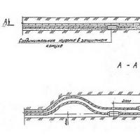 Requirements and rates for cable laying in Earth Scope of application, Definitions
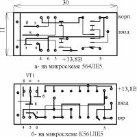 Automobile stroboscope from laser pointer
 Order 20 UAH to the account. How to Borrow on MTS. Additional information on the service
 How to check the account replenishment
 How to get a loan on tele2?
 Responsiveness SSD on a miniature board What SSD Drive Buy