How to make a mirror image of the drawing. Mirror reflection of objects
Before starting drawing, make sure that the dynamic input is enabled.
We build a rectangle (half the left of the whole part). To do this, activate the "Rectangle" tool and click on the screen indicate the left lower corner of the rectangle (you can, on the contrary, the right upper one), then we enter the relative decartum coordinate of the opposite angle - 70,120, ENTER.
Draw lines inside a rectangle. You will bring the cursor to the left side of the rectangle, the binding "Content" appears, without clicking the direction to the right, enter from the keyboard 45, ENTER, specify the direction down, enter from the keyboard 30, ENTER, indicate the direction to the right, enter from the keyboard 25, ENTER, ENTER .
We carry the cursor on the left lower corner of the rectangle, the binding "Content" appears, without Specifying the direction to the right, enter from the keyboard 50, ENTER, indicate the edge direction, enter from the keyboard 90, ENTER, ENTER.
We curly the left top corner of the rectangle. Turn on the "Conjugation" tool, in command line Check the "Pruning" option. If the "cropping" mode is all right, if not, click the right mouse button, select the "Pruning" option, choose "with trimming". Click the right mouse button, select the "Radius" option, indicate the radius 30, ENTER, build a pairing. Click on one side, click on the second side.
Turn on the "Trim" tool, click on the edge of the shape, enter, click on the right side of the figure, the side is removed, ENTER. We allocate everything, activate the "Mirror" tool, click at the right bottom point of the figure, then at the right upper point, ENTER.
Turn on the "Trim" tool, click on the edge of the right part of the figure, enter, click on the right side of the figure, the side is removed, ENTER.
Turn on the "Polyline" tool (or "segment"), tie to the right lower corner of the figure, indicate the direction of the down, enter from the keyboard 20, ENTER, indicate the direction to the right, enter from the keyboard 55, ENTER, indicate the upward direction, enter from the keyboard 90, ENTER, indicate the direction to the left, enter from the keyboard 5, ENTER, indicate the direction upwards, enter from the keyboard 120, ENTER, indicate the direction to the left, enter from the keyboard 30, ENTER, indicate the direction of the down, enter from the keyboard 100, ENTER, we carry the cursor to the left right right The upper angle of the figure, before the binding of the "Content", click, ENTER.
Turn on the "Polyline" tool (or "segment"), tie to the right lower corner of the shape, indicate the direction to the right, enter from the keyboard 15, ENTER, ENTER.
Turn on the "Polyline" tool (or "segment"), tidy to the right top corner Figures, specify the direction to the right, enter from the keyboard 20, ENTER, ENTER.
We allocate everything, activate the "Mirror" tool, click at the right bottom point of the figure, then at the right upper point, ENTER.
Exercise performed.
|
Add a comment
Name: E-mail: Spam protection: one thousand six hundred ninety two (number):* |
Mirror image allows you to create mirror copies of objects with respect to the specified axis.
Mirroring objects are made relative to the reflection axis. The reflection axis is set by two points. You can select deletion or save the source objects.
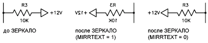
According to the default settings, with mirror reflection, texts, hatching, attributes and attribute definitions do not apply to the right left and do not turn over. Alignment and indenting text remain the same as before the operation of the mirror reflection. If the text circuit on the right left is still needed, set the value 1 for the MirRText system variable.
The MirRText variable affects the text that is created using commands text, ATOPR or MTEX, as well as on attribute definitions and attribute variables. With a mirror reflection of the block, the text and constant attributes that are part of the inserted block are referred to regardless of the MirRText parameter value.
Mirrhatch system variable affects hatch objects created by the gradient or barcode commands. To control the mirror reflection or preservation of the direction in the shading sample, the system variable MIRRHATCH is served.
Mirror reflection in three-dimensional space (not available in AutoCAD LT)
Using the 3D server command, you can mirror the objects relative to the specified reflection plane. The reflection plane may be:
- Plane of building 2D object
- Plane parallel to one of the planes of coordinates ( XY., Yz. or Xz.) current PSK and passing through a specified point
- The plane is determined by three specified points (2, 3 and 4)
In this lesson, let's talk about how to reflect in the autocada. Let us consider in detail how to reflect the sirral in the auto channel elements of the drawing. We will understand how to reflect the object in the autocada to save a bunch of time and exclude possible mistakes When building symmetric parts.
How to reflect in autocada
You already know. Introduced the queue of mirror reflection. What can be reflected? As you already guessed, in this lesson it will be about symmetric objects.
The "Reflect Mirror" button in the auto channel is in the edit block, click on it. Mouse cursor is displayed as a small square, they allocate them the right lines Drawing, just clicking on them.

Select all the required lines, press the "Enter" button. Now you need to select the first point for the mirror image.
As the first point, it is convenient to choose the intersection of the drawing line along the axis of symmetry. Now when moving the mouse pointer, the reflected image is rotated. We choose the second point on the axis of symmetry to the right, so the reflection will be rotated mirror. If you need to reflect on an arbitrary angle, then we put the second point in an arbitrary place as soon as the image turns to the desired angle. The next step must be selected to leave the source object, or delete.

We put the point at the desired solution, confirm the "Enter" key. Reflection built.
The symmetry axis can be located at a distance from the object. You can reflect both horizontally and vertically and at any angle. The reflection in the autocadus is twice, allows you to significantly simplify the construction of the drawing.

A simple example. We build a quarter of the part images, create a mirror reflection relative to the vertical axis of symmetry, and then half the image reflect relative to the horizontal axis. Simply and easily.
As you were convinced, there is nothing complicated. In the next lesson, consider how to do. On this note, our today's lesson is completed. For more questions, I propose to ask in the comments under the article.
So, we use an existing object representing the left wall of the left wall of the small couch on the drawing to create on its basis using the tool. Mirror reflection Exactly the same object, which is a mirror image of the first.
Tool Mirror reflection Allows you to create copies of symmetrically arranged drawing elements relative to the axis of the mirroring, determined by two points. Since the display accuracy depends on the correctness of the axis choices, it is very important to represent well what the result must be obtained. In some cases, when the advantage of the mirror image is obvious, you can even draw an auxiliary line to facilitate the task of selecting the endpoints of the axis of the mirroring. But in our case this does not have to do, since the axis of the mirror image is already available in the drawing. True, it is necessary to use the new object binding for you to visualize it.
1. Click on the button Mirror reflection Toolbars Change or select the command from the menu Change »Mirror either enter the command in the command window Mirror.
2. In response to the invitation to select Objects, click on the left side wall loop with a small stand and press ENTER to complete the selection. Invitation will appear in the command window The first point of the reflection axis:.
3. Click the button Middle Toolbars Object binding. The object binding mode to the mid-point will turn on (in the AutoCAD command window automatically enters the command _mid.). In this mode, AutoCAD can recognize the midnings of objects.
4. Move the crosshair pointer to the middle of one of the vertical lines denoting the contour of the facade of the small couch. As soon as AutoCAD recognizes the middle of the line, a triangular marker will appear on the screen. Click to capture the coordinates of this point.
5. Invitation will appear in the command window The second point of the axis of reflection:, And the reflected image of the source object appears on the drawing, which will move according to the movement of the axis of the mirroring, which is determined by the first selected point and the current position of the crosshair pointer. 6. Re-enable binding mode Middle And select the middle of the second vertical segment of the contour of the facade of small couch (Fig. 4.52).

Fig. 4.52 Displays the side wall relative to the axis passing through the middle of the vertical segments of the facade
7. The reflected image will disappear, and a request will appear in the command window Delete source objects [Yes / No]:. This request means that before completing the command Mirror Can delete the source object, leaving only its mirror copy in the drawing. In this case, we do not need it, so press ENTER to refuse to remove.
8. The drawing will appear a mirror image of the right wall of the small cabinet, and the team Mirror Complete its work.
To complete the drawing, we have to do quite a bit of work: create contours of the side walls of the couch system Block and large stands, the contour of the facade of the large stands and the contours of three cuts in the facades of small and big tumb, as well drawer Tables (in these cutouts there will be mortise knobs). In addition, it is necessary to complete the work on the circuits of the shelves located in the left corner of the working area (see Fig. 4.1-4.3). Now you are quite ready to solve the last task, so we will begin with it.
 Cellular - what it is on the iPad and what's the difference
 Go to digital television: What to do and how to prepare?
 Social polls work on the Internet
 Savin recorded a video message to the Tyuments
 Menu of Soviet tables What was the name of Thursday in Soviet canteens
 How to make in the "Word" list alphabetically: useful tips
 How to see classmates who retired from friends?