Table of additional formats. Dimensions of all paper formats. Drawing formats and drawing sheets
Not so long ago, the engineers performed drawings each, as he could have been able to, were not monotony in the design and design of project documentation. Because of what difficulties arose in understanding the drawings. To solve this problem in the USSR in 1929, the first compilation was formed and issued standards "Drawings in mechanical engineering." It is believed that in 1929 there was a significant shift in the process of industrialization of the country. These standards were created mainly for machine-building production, in 1965-1968 it was decided to replace the current standards for a "unified system of design documentation" (ECCD), acting throughout the country.
Unified Design Documentation System (ECCD) - Complexstate standards establishing general rules for the development and design of design documentation (in designing, development, manufacturing, control, acceptance, operation, repair, recycling).
ECCD standards Digital code 2 assigned, and the whole complex eCCD standards Located for ten classification groups that are numbered from 0 to 9.
For example, GOST 2.301-68 ** :
2 - suggests that the document is the ECC standard;
3 - numbers after the point indicates the ECC classification group "General rules for the implementation of the drawings";
01 - Number of this standard in the ECC formats group
68 - year of registration of the standard - 1968
If the GOST was made after the publication, then at the end of the number put an asterisk * if additional changes were made, then another asterisk adds **.
To fulfill the design documentation of all industries and construction, the formats of the drawings made in electronic or paper form are provided.
Formats of sheets are determined by the size of the outer frame (made by the fine line) of originals, original, duplicates, copies. The limit deviation of the sizes of the formats of ± 5%.
From above and from below, from the outer and inner frame of a sheet of 5 mm, on the right - 5 mm, on the left - 20 mm under the table with additional graphs and for the drawing brochure. In brackets, the sizes of the framework on the sheets of the re-use project (typical project) are indicated.
The most running formats are considered to be A4, A3, A2, A1, A0. The area of \u200b\u200bwhich is 1 m 2, the size of other formats is obtained by a sequential division into two equal parts, designations and dimensions are shown in the table below:
Designation of forms. |
44 |
24 |
22 |
12 |
11 |
Sizes of the sides of the format in mm |
1189x841. |
594x841. |
594x420. |
297x420 |
297x210 |
. Design. consumerpaper format according to GOST 9327-60 * |
A0.(1 m 2) |
A1.(1/2 A0) |
A2.(1/2 A1) |
A3.(1/2 A2) |
A4.(1/2 A3) |
It is often necessary to perform drawings of very large parts or structures, such as locomotive parts, car, construction of buildings, bridges and very small - details of the hourly mechanism, some devices, etc. Drawings of large parts (designs) are not placed on sheets of standard format. Small details that can be barely noticeable with the naked eye, it is impossible to draw in the natural value of existing drawing tools. Therefore, in drawings, the images of large parts are reduced, and the small increases compared with the actual dimensions.
The scale is the ratio of the linear dimensions of the subject shown in the drawing to its size in nature. Scale can be expressed by the number (numeric scale) or is depicted graphically (linear scale).
Numerical scaledenote by a fraction that shows the multiplicity of zoom in or reducing the size of the image in the drawing. When performing drawings, depending on their purpose, the complexity of the forms of objects and structures, their size apply the following numerical scales (GOST 2.302-68) *: - 64 pcs.
Formats of sheets are determined by the size of the outer frame. It is drawn on the drawings of the fine line (Fig. 1 and 2).
Main formats:
|
Designation |
|||||
| Sides, mm | 841x1189. | 594x841. | 420x594. | 297x420 | 210x297 |
The most common paper format is A4 format (210 x 297 mm). For technical documentation, such as schemes, drawings, diagrams, are usually used from A4 to A1.


| Format | Series A. | Series B. | Series C. |
|---|---|---|---|
| The size | mM. | mM. | mM. |
| 0 | 841 x 1189. | 1000 x 1414. | 917 x 1297. |
| 1 | 594 x 841. | 707 x 1000. | 648 x 917. |
| 2 | 420 x 594. | 500 x 707. | 458 x 648. |
| 3 | 297 x 420. | 353 x 500. | 324 x 458. |
| 4 | 210 x 297. | 250 x 353. | 229 x 324. |
| 5 | 148 x 210. | 176 x 250. | 162 x 229. |
| 6 | 105 x 148. | 125 x 176. | 114 x 162. |
| 7 | 74 x 105. | 88 x 125. | 81 x 114. |
| 8 | 52 x 74. | 62 x 88. | 57 x 81. |
| 9 | 37 x 52. | 44 x 62. | 40 x 57. |
| 10 | 26 x 37. | 31 x 44. | 28 x 40. |
Envelope format
The most popular DL envelope (110 x 220 mm), the A4 sheet is placed in it, threefold. For wedding invitations Good formats C6 and DL
Envelopes with dimensions 114 x 162 mm (C6), 110 x 220 mm (DL), 162 x 229 mm (C5) are made with windows on the site of the addressee address zone, then they are denoted: C6 / O; DL / O; C5 / O.
Additional formats:
The designation of the derivative format is made up of the designation of the main format and its multiplicity, for example, A0X2, A4X8, etc.
| Multiplicity | Format | ||||
| A0. | A1. | A2. | A3. | A4. | |
| 2 | 1189x1682. | - | - | - | - |
| 3 | 1189x2523. | 841x1783. | 594x1261 | 420x891. | 297x630. |
| 4 | - | 841x2378. | 594x1682. | 420x1189 | 297x841. |
| 5 | - | - | 594x2102. | 420x1486. | 297x1051 |
| 6 | - | - | - | 420x1783. | 297x1261 |
| 7 | - | - | - | 420x2080. | 297x1471 |
| 8 | - | - | - | - | 297x1682. |
| 9 | - | - | - | - | 297x1892. |
Location of the main lettering:
On all formats (except A4), the inscription can be placed both along the long and along the short sides of the format (see Fig. 2). An additional graph on all formats (except A4) is located along the long side. On A4 sheets, the main inscription is located along the short side, because This format is used only with a vertical arrangement of the long side (see Fig.3).
Formats according to GOST 2.301-68
The formats of the sheets of drawings must correspond to GOST 2.301-68.
Sheet formats are determined by the size of the outer frame (Fig. 1)
Main format - The format, the largest of which it has the size of the parties 1189x841 mm (area 1M 2), and the subsequent formats, it receives the sequential division of it into two equal parts parallel to the smaller side.
Additional format - The format is formed by an increase in the short side of the main format by magnitude, a multiple size of its size.
| Main formats | Additional formats | |||
|---|---|---|---|---|
| Designation | The designation is old | Sizes mM. |
Designation | Sizes mM. |
| A0. | 44 | 841 × 1189. | A0 × 2. | 1189 × 1682. |
| A0 × 3. | 1189 × 2523. | |||
| A1. | 24 | 594 × 841. | A1 × 3. | 841 × 1783. |
| A1 × 4. | 841 × 2378. | |||
| A2. | 22 | 420 × 594. | A2 × 3. | 594 × 1261. |
| A2 × 4. | 594 × 1682. | |||
| A2 × 5. | 594 × 2102. | |||
| A3. | 12 | 297 × 420. | A3 × 3. | 420 × 891. |
| A3 × 4. | 420 × 1189. | |||
| A3 × 5. | 420 × 1486. | |||
| A3 × 6. | 420 × 1783. | |||
| A3 × 7. | 420 × 2080. | |||
| A4. | 11 | 210 × 297. | A4 × 3. | 297 × 630. |
| A4 × 4. | 297 × 841. | |||
| A4 × 5. | 297 × 1051. | |||
| A4 × 6. | 297 × 1261. | |||
| A4 × 7. | 297 × 1471. | |||
| A4 × 8. | 297 × 1682. | |||
| A4 × 9. | 297 × 1892. | |||
| A5. | 148 × 210. | - | - | - |
|
Note - A5 format is allowed to apply if necessary. |
||||
The limit deviations of the sides of the formats are shown in Table 2.
GOST 3450-60 Formats
(Canceled)
GOST 3450-60 Sets the formats of drawings and stipulated by standards on a system of drawing economics of technical documents performed on separate sheets or on one general sheet with the selection of formats in it for each drawing (document).
Determining sheet sizes are sizes of copies after cutting.
The main and additional formats and their designation must comply with those specified in Tables 3, 4 and in Fig. 3.
Notes:
1. The use of format 148 × 210, denoted by ½ 1 and corresponding to the consumer paper format A5.
2. It is allowed to perform drawings on sheet drawing paper according to GOST 597-56 with the preservation of the working field of the drawing inside the frame according to GOST 5293-60.
| Designation of format | Dimensions of the sides of the sheet, mm | Designation of format | Dimensions of the sides of the sheet, mm |
|---|---|---|---|
| 13 | 297 × 631. | 25 | 594 × 1051. |
| 14 | 297 × 841. | 26 | 594 × 1261. |
| 15 | 297 × 1051. | 26 | 594 × 1472. |
| 16 | 297 × 1261. | 27 | 594 × 1682. |
| 17 | 297 × 1472. | 28 | 594 × 1892. |
| 32 | 892 × 420. | 54 | 1486 × 841. |
| 42 | 1189 × 420. | 64 | 1783 × 841. |
| 52 | 1486 × 420. | 74 | 2081 × 841. |
| 62 | 1783 × 420. | 84 | 2378 × 841. |
| 72 | 2081 × 420. | 94 | 2675 × 841. |
In addition to the formats specified in Tables 1 and 2, in exceptional cases, the use of special formats formed by the increase in format 11 is allowed, as shown in Fig.3, and the increase coefficient must be an integer.
 Fig.3. |
Notes:
1. The construction of basic and additional formats is shown by solid lines, and special formats - barcccints.
2. The designation of the basic and additional formats is indicated by bold.
3. The designation of the main formats is circled.
4. The designation of format 11 (297 × 210), taken per unit of measurement of other formats, circled by a double circle.
The designations of formats should be made up of two digits (numbers), the first of which indicates the multiplicity of one side of the format to a value of 297 mm, and the second is the multiplicity of the other side to a value of 210 mm.
The product of the numbers constituting the format designation determines the number of formats 11 (i.e., 297 × 210 format), which is contained in this format. For example, format 74 consists of 7 × 4, i.e. 28 formats 11.
With the designation of special formats, double-digit numbers indicating the multiplicity of their parties to the corresponding sides of the format 11 are separated by a point. For example, format 2.10 - 594 × 2102, format 10.4 - 2972 \u200b\u200b× 841.
To calculate the sizes of the sides, 297.25 and 210.25 mm are taken with rounding to 1 mm in the direction of increasing with the values \u200b\u200bof the amount of sepate\u003e 0.5 and towards the decrease - with values \u200b\u200bof ≤0.5.
LITERATURE
- GOST 2.301-68 ECCD Formats
- GOST 3450-60 Formats
- GOST 9327-60 Paper and paper products. Consumer Formats
- Machine-building drawing: Directory / GN Popova, S.Yu. Alekseev. - SPb.: Polytechnic, 2006. - 456 p.
- Quick reference book on descriptive geometry and machine-building draw / N.P. Savings, M.A. Coat of arms. M.-L., Mechanical Engineering, 1965, 264 p.
- Reference Guide for Drawing / E.I. Godik, A.M. Huskin. M., Mechanical Engineering. 1974, 696 p.
GOST 2.301-68.
Group T52.
Interstate standard
Unified system of design documentation
Unified System for Design Documentation. Formats.
ISS 01.100.01
Date of introduction 1971-01-01
Approved by the Resolution of the Standards Committee, measures and measuring instruments at the Council of Ministers of the USSR of May 28, 1986 N 751
Instead of GOST 3450-60
Change N 3 adopted by the Interstate Council for Standardization, Metrology and Certification on Penicing (Protocol No. 23 of February 28, 2006)
The adoption of the change voted national authorities to standardize the following states: AZ, AM, BY, KZ, KG, MD, RU, TJ, TM, UZ, UA [Alpha-2 codes on MK (ISO 3166) 004]
Edition (August 2007) with changes in N 1, 2, approved in December 1980, March 1989, June 2006 (IUS 3-81, 7-89, 9-2006).
1. This standard establishes the formats of sheets of drawings and other documents performed in electronic and (or) paper form provided by the standards for the design documentation of all industries and construction.
(Modified edition, meas. N 2, 3).
2. Formats of sheets are determined by the size of the outer frame (made by the fine line) of originals, original, duplicates, copies (Chert.1).
When displaying a document in electronic form on a paper carrier with the size of the sheets of the sheet, which coincides with those specified in Table 1, the external frame of the format is allowed not to be performed. If the size of the sides of the sheet is more specified in Table 1, then the external format frame must be reproduced.
(Modified edition, meas. N 3).
3. The format with sizes of 1189x841 mm, the area of \u200b\u200bwhich is 1 m, and other formats obtained by sequential division of it into two equal parts parallel to the smaller side of the corresponding format are taken for the main.
4. The designations and dimensions of the parties of the main formats must be consistent with the specified in Table 1.
Table 1
Designation of format | Sizes of the sides of the format, mm |
If necessary, it is allowed to apply A5 format with sizes of 148x210 mm.
5. It is allowed to apply additional formats formed by an increase in short sides of the main formats by magnitude, multiple their size.
Dimensions of derivative formats, as a rule, should be chosen in Table 2.
The designation of the derivative format is made up of the designation of the main format and its multiplicity according to Table 2, for example, A0X2, A4X8, etc.
table 2
Multiplicity | Format |
||||
6. Limit deviations of the parties to the formats - according to Table 3.
Table 3.
Sizes of the sides of format | Limit deviations |
St. 150 to 600 | |
4-6. (Modified edition, meas. N 1).
7, 8. (excluded, meas. N 1).
9. Documents in electronic form in its proper part must contain the designation of the format of the paper carrier sheet, when the display is output to which the display scale will correspond to the specified one.
(Introduced additionally, meas. N 3).
Electronic document text
prepared Codex JSC and drilled by:
official edition
Unified system of design documentation:
Sat Gostov. - M.: Starotinform, 2007
Format They are called linear dimensions of drawings and other technical documentation. The defining sizes of drawing formats (GOST 2.301-68) are the size of an outer frame made by a thin line. The inner frame is carried out by a solid main line at a distance of 20 mm from the left side of the outer frame and at a distance of 5 mm from the rest of the sides.
Formats are divided by maintenance and additional. The main formats include the format with sizes of 841,1189 mm, the area of \u200b\u200bwhich is approximately equal to 1 m 2, and the remaining formats obtained by sequential division of the previous main format into two equal parts parallel to its smaller side (Table 1).
Table 1
Main drawing formats
|
Designation | ||||||
|
Sides, mm |
* Applied as needed
It is allowed to use additional formats formed by an increase in short sides of the main formats by magnitude. k. (integer called multiplicity additional format). The designation of the additional format consists of the designation of the main format and its multiplicity. For example, an additional A3 × 4 format has a multiplicity of 4, and its dimensions are 420 × 1189 mm.
All formats except A4 can be located both vertically and horizontally. A4 format is located only vertical (Fig. 2).
2.2. Main inscriptions
Basic inscription - This is a combination of the established characteristics of the product listed in a special stamp, which is located in the lower right corner of the drawing (GOST 2.104-2006). On the sheets of A4 format, the main inscription is located in its lower part along the short side.
Three forms of the main inscriptions are provided for the design of drawing and design documentation:
for first sheet drawings and schemes (Form 1 - Fig. 3);
for first sheet of text design documents (form 2);
for subsequent sheets of drawings, diagrams and text design documents (form 2a).

In the main inscription in form 1, the following graphs must be filled (Fig. 3).
IN column 1. - Product name in accordance with the requirements of GOST 2.109-73.
IN column 2. - Document designation according to GOST 2.201-80 (for example, IG.01.02.14 - Fig. four).
IN column 3. - Designation of material Details indicating the GOST to this material.
IN column 4. - Scale in accordance with GOST 2.302-68.
IN column 5. - The sequence number of the sheet (on documents consisting of one sheet, this graph is not filled).
IN column 6. - The total number of document sheets (filled only on the first sheet).
IN column 7. - the name of the enterprise (for example, SNGGI (TU), Department of NGIG, GM-08-1 group).
IN column 8. - the names of those who signed the document.
IN column 9. - signatures of people whose names are listed in column 8.
IN column 10. - date of signing the document.

All graphs, in addition to signatures and dates, are filled with a pencil, standard font (information on letters and numbers, on font sizes that are used to perform inscriptions in the drawings, is shown below).
It is necessary to pay attention to the fact that in the image of the main inscription there are basic and thin lines.
 Lighting devices based on alternating current LEDs find their niche and may come out beyond its limits.
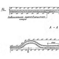 Requirements and rates for cable laying in Earth Scope of application, Definitions
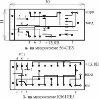 Automobile stroboscope from laser pointer
 Order 20 UAH to the account. How to Borrow on MTS. Additional information on the service
 How to check the account replenishment
 How to get a loan on tele2?
 Responsiveness SSD on a miniature board What SSD Drive Buy