XPX antenna GPS pinout HDMI connector. Pickup HDMI connector and cable in pictures. Description of the appointment of some conclusions
HDMI cable for its structure is reminded by a well-known "twisted pair" well, but it only consists of a larger number - 19. Knowing the cable pinout circuit, you can connect an HDMI outlet or restore the damaged connector.
Many may ask: why repair a damaged HDMI cable or its connector? It is easier to buy a new wire, the benefit of prices for it is now more than democratic. For example, you can purchase within 1000 rubles. And it will meet all modern standards: High Speed \u200b\u200bWith Ethernet, 3D and 4K support.
We answer: what if the cable is laid in the wall or corrugation and it is not possible to pull it out and replace it? Or are you a connoisseur of top Hi-End brands and you use HDMI cables only premium class, the cost of which start from several thousand rubles per 1 meter?!
In this case, it is possible to significantly save on the purchase of a new cable, replacing a damaged HDMI connector.
So, without going into technical details, consider the pinout of any modern HDMI cable (High Speed \u200b\u200bClass with Ethernet).
Type A Connector HDMI pinout (19pin)
Pinout HDMI cable from inside
As you can see, the HDMI cable is divided into 5 groups of 3 veins. And 4 more veins go separately (not grouped).

There is no single color marking lived, and each cable manufacturer may have its own marking. In our HDMI cable instance, the following was used:

Let's try on the example this cablewhich is sold in cutting (there are also such), demonstrate its cutting and ending.
Cutting HDMI Cable
1. We clean the HDMI cable from the outer shell.

2. Screen braid shift, freeing the wires of the wires.

3. We form the contact groups and we clean them.

4. As a connector to the cable, we use the socket module.


This module It is convenient because you can independently end the HDMI cable without a special set of expensive crimping equipment. And placing it in the frame, you will have a full HDMI socket.
5. According to the table, each wire is clamped into the clermets of the module.

Thus, when repairing or construction, you can lay the HDMI cable required length into the wall. Click it from both sides by the rosette module Dr.HD HDMI under the frit.


Consider the case when the HDMI cable broke the connector.

We act on the same items.
1. Clean the cable, we release and form a group of wires.

2. Since the cross section lived here less and the wire is multiple, their irradiation will be required.
To find out which of the A / B / C / D / E groups, the tester will be required (transk). Only after you have determined the correct grouping of wires, as well as four wires without a group, you can proceed to crimp.

We successfully tested the operation of this restored cable. The source was Blue-ray drive and 3D roller. We did not see any digital interference.
HDMI cable for its structure is reminded by a well-known "twisted pair" well, but it only consists of a larger number - 19. Knowing the cable pinout circuit, you can connect an HDMI outlet or restore the damaged connector.
Many may ask: why repair a damaged HDMI cable or its connector? It is easier to buy a new wire, the benefit of prices for it is now more than democratic. For example, 5 meter HDMI cable can be purchased within 500 rubles. And it will meet all modern standards: High Speed \u200b\u200bWith Ethernet, 3D and 4K support.
We answer: what if the cable is laid in the wall or corrugation and it is not possible to pull it out and replace it? Or are you a connoisseur of top Hi-End brands and you use HDMI cables only premium class, the cost of which start from several thousand rubles per 1 meter?!
In this case, it is possible to significantly save on the purchase of a new cable, replacing a damaged HDMI connector.
So, without going into technical details, consider the pinout of any modern HDMI cable (High Speed \u200b\u200bClass with Ethernet).
Type A Connector HDMI pinout (19pin)

Pinout HDMI cable from inside
As you can see, the HDMI cable is divided into 5 groups of 3 veins. And 4 more veins go separately (not grouped).
There is no single color marking lived, and each cable manufacturer may have its own marking. In our HDMI cable instance, the following was used:

Let us try on the example of this cable that is sold in the cutting (there are also such), to demonstrate its cutting and ending.
Cutting HDMI Cable
1. We clean the HDMI cable from the outer shell.
2. Screen braid shift, freeing the wires of the wires.

3. We form the contact groups and we clean them.

4. As a connector to the cable, we use the rosette module Dr.HD HDMI under crimp.

This module is convenient because you can independently end the HDMI cable without a special set of expensive crimping equipment. And placing it in the frame, you will have a full HDMI socket.
5. According to the table, each wire is clamped into the clermets of the module.

Thus, when repairing or construction, you can lay the HDMI cable required length into the wall. Click it from both sides by the rosette module Dr.HD HDMI under the frit.

Consider the case when the HDMI cable broke the connector.

We act on the same items.
1. Clean the cable, we release and form a group of wires.
2. Since the cross section lived here less and the wire is multiple, their irradiation will be required.
To find out which of the A / B / C / D / E groups, the tester will be required (transk). Only after you have determined the correct grouping of wires, as well as four wires without a group, you can proceed to crimp.

We successfully tested the operation of this restored cable. The source was Blue-ray drive and 3D roller. We did not see any digital interference.
It often happens that the HDMI cables are consistent. The author of the articles at one time worked as a seller-consultant in the store household appliancesTherefore, it knows how bad knows how unreliable in places where the connectors are located, that is, the ends of the cables.
These wires are very poorly carrying bends and regular reinstallations. Ideally, they need to put them, and do not touch at all, but in practice, we often connect to TV laptops and other techniques, and HDMI, you want, do not want, begins to suffer.
If you have happened so that the signal cable has stopped, but in stock there is another from which you can remove the working connectors, then you can learn how to dispens the HDMI cable, and continue to enjoy all the advantages digital television. Well, or run in the store for a new one - who what!
Many readers may have a reasonable question - why communicate with the soldering, when for quite modest money you can go and buy a new one that we will reply the following:

- Firstly, not always under the side of the store in which you can purchase such products, and not always such shops are open - especially relevant for villages and small towns.
- Secondly, not everyone craves to buy a cheap cable, especially if before it was good - agree that the example is controversial, but still.
- Thirdly, imagine the situation that you already have two cables, and both have one broken and one working connector. Why not take, and not make one worker cable without spending money? It is interesting and economically!
- Fourth, the length of the available HDMI cable can be rapidly missing you, and you want to lengthen it. Well, or the connector simply does not go into the hole in the wall and you do not want to expand this very hole.
In general, the reasons can be as you like, since the situation, sometimes, the most unforeseen.
How to understand that the cause of a malfunction in the cable

How can a problem with a faulty cable can be manifested:

- The TV gives the inscription on the screen: "No video signal";

- The image is fuzzy, covered with noise, with a possible color displacement toward blue, red or green;

- Instead of the usual clip art, the TV gives you here such artifacts in the form of strips of squares and other patterns;

- Image on site, but there is no sound.
- Other symptoms are also possible, but the essence is one - first of all are always checked for the performance of cables, and then the technique.

Do not think that we mock, but really, very often, inexperienced users cannot understand that the active entrance on the TV is changed. So if you see this snow on the screen, then take the remote, look for the input shift button (do not know it "in the face", look into the instruction), which may be called "Input", "TV \\ in", "Source" and Other. Next, choose from the proposed list you need.
If you have at least once kept a similar cable in your hands, you should know that its "body" is made sufficiently strong and flexible, so if there are no visible damage on it, the problem can only be associated with the connectors. How to make sure that fault?
Here is a brief, but effective instruction:
- First of all, try to move the connector slightly to the TV.
- If nothing happens, then pull it out HDMI and stick it back - sometimes such measures help restore the image and sound, as it often happens that there is no normal contact.
- The next step is to change the cable and input, for example, to connect tulips that most video equipment still are equipped. If the image is restored, then you can draw conclusions.
- Make a visual inspection of the connectors - they can be curved or divided into generally. Here all questions are immediately removed.

Contacts VGA, DVI, HDMI, YC, SCART connectors
Spacking cables for signals YUV (Y / PBCB / PRCR), VGA HD15, DVI, HDMI, S-Video, SCART (Peritel, Euroconnector).
Contacts VGA, DVI, HDMI, YC, SCART connectors
VGA HD15 Connector Contacts
Cont. |
Signal |
Description |
| 1 | Red | Channel R (red) (75 ohms, 0.7 V) |
| 2 | Green. | Channel G (green) (75 ohms, 0.7 V) |
| 3 | Blue | Channel in (blue) (75 ohms, 0.7 V) |
| 4 | ID2. | Identification Bit 2. |
| 5 | GND. | Land |
| 6 | RGnd. | Channel land R. |
| 7 | GGnd. | Channel G. |
| 8 | BGnd. | Channel Land B. |
| 9 | Key | No contact (key) |
| 10 | SGND. | Land synchronization |
| 11 | Id0 | Identification bit 0. |
| 12 | ID1 OR SDA | Identification Bit 1 or DDC data |
| 13 | Hsync or Csync. | Scroll or composite synchronization |
| 14 | Vsync. | Personnel synchronization |
| 15 | ID3 OR SCL. | Identification Bit 3 or DDC Tracies |
Spacking cable KRAMER BC5X5S (5-coax)

Spack Cable Kramer BC3X2T7S (3-coax, presentation)

Solving YUV signal (Y / PBCB / PRCR) from the VGA HD15 connector (for Kramer VP-41 4 (XL) scales, VP-419XL, VP-420, VP-421, VP-724XL, VP-728, VP-729, VP-730, VP-731, VP-725XL, VP-727, VP-747)

Contacts connector DVI-I / DVI-D

Cont. |
Signal (eng.) |
Signal (Rus) |
| 1 | T.M.D.S DATA 2- | T.M.D.S 2- |
| 2 | T.M.D.S DATA 2+ | T.M.D.S 2+ data |
| 3 | T.M.D.S DATA 2/4 SHIELD | Screen for data T.M.D.S 2 and 4 |
| 4 | T.M.D.S DATA 4- | T.M.D.S 4- |
| 5 | T.M.D.S DATA 4+ | T.M.D.S 4+ data |
| 6 | DDC Clock. | Tracked DDC. |
| 7 | DDC Data. | DDC data |
| 8 | Analog Vert. Sync. | Analog Personnel Sync. |
| 9 | T.M.D.S DATA 1- | T.M.D.S data 1- |
| 10 | T.M.D.S DATA 1+ | T.M.D.S 1+ data |
| 11 | T.M.D.S DATA 1/3 SHIELD | Screen for T.M.D.S 1 and 3 data |
| 12 | T.M.D.S DATA 3- | T.M.D.S 3- |
| 13 | T.M.D.S DATA 3+ | T.M.D.S 3+ data |
| 14 | + 5V Power | Power +5 B. |
| 15 | GND. | Land |
| 16 | Hot Plug Detect. | Sensor "Hot" connection |
| 17 | T.M.D.S DATA 0- | T.M.D.S data 0- |
| 18 | T.M.D.S DATA 0+ | T.M.D.S 0+ data |
| 19 | T.M.D.S DATA 0/5 SHIELD | Screen for data T.M.D.S 0 and 5 |
| 20 | T.M.D.S DATA 5- | T.M.D.S 5- |
| 21 | T.M.D.S DATA 5+ | T.M.D.S 5+ data |
| 22 | T.M.D.S CLOCK SHIELD. | Screen for tacht t.m.d.s |
| 23 | T.M.D.S CLOCK +. | Tracked t.m.d.s +. |
| 24 | T.M.D.S CLOCK- | Tracked t.m.d.s - |
| C1. | Analog Red | Analog Channel R. |
| C2. | Analog Green. | Analog Channel G. |
| C3. | Analog Blue | Analog Channel B. |
| C4. | Analog Horz Sync. | Analog line sync. |
| C5. | Analog Ground | Analog land |
HDMI connector contacts (Single Link, Type A, up to version 1.4 inclusive)

Cont. |
Signal (eng.) |
Signal (Rus) |
| 1 | T.M.D.S DATA 2+ | T.M.D.S 2+ data |
| 2 | T.M.D.S DATA 2 SHIELD | T.M.D.S 2 data screen |
| 3 | T.M.D.S DATA 2- | T.M.D.S 2- |
| 4 | T.M.D.S DATA 1+ | T.M.D.S 1+ data |
| 5 | T.M.D.S DATA 1 SHIELD | T.M.D.S 1 data screen |
| 6 | T.M.D.S DATA 1- | T.M.D.S data 1- |
| 7 | T.M.D.S DATA 0+ | T.M.D.S 0+ data |
| 8 | T.M.D.S DATA 0 SHIELD | T.M.D.S 0 data screen 0 |
| 9 | T.M.D.S DATA 0- | T.M.D.S data 0- |
| 10 | T.M.D.S CLOCK +. | Tracked t.m.d.s +. |
| 11 | T.M.D.S CLOCK SHIELD. | Screen for tacht t.m.d.s |
| 12 | T.M.D.S CLOCK- | Tracked t.m.d.s - |
| 13 | Cec. | Consumer Electronics Control Network |
| 14 | Utility. | Used for HEAC (Ethernet and Reverse Audio Channel) |
| 15 | DDC Clock. | Tracked DDC. |
| 16 | DDC Data. | DDC data |
| 17 | DDC / CEC GND | Earth for DDC and CEC |
| 18 | + 5V Power | Power +5 B. |
| 19 | Hot Plug Detect. | Sensor "Hot" connection |
S-VIDEO connector contacts (YC, S-VHS)
Standard 4-pin MINIDIN connector

7-pin MINIDIN connector (found in aTI video cards and etc.)

10-pin connector (in the ATI All-in-Wonder video cards)
Cont. |
Signal |
Description |
| 1 | C. | Channel C (color) |
| 2 | S / PDIF Ground | S / PDIF signal |
| 3 | SPDIF. | SPDIF signal (digital audio) |
| 4 | GND. | Land |
| 5 | GND. | Land |
| 6 | R. | Audio, Right Channel |
| 7 | GND. | Audio land |
| 8 | Y. | Channel Y (Brightness + Synch.) |
| 9 | V. | Composite video |
| 10 | L. | Audio, left canal |
10-pin connector (in Matrox G450 video cards, etc.)
Cont. |
Signal |
Description |
| 1 | C (S-Video) | Channel C (color) |
| 2 | GND. | Land |
| 3 | Y. | Channel Y (Brightness + Synch.) |
| 4 | RGB SWITCHING CONTROL | Control signal |
| 5 | Composite Sync. | Output of composite synchronization |
| 6 | GND. | Land |
| 7 | V. | Composite video |
| 8 | L. | Audio, left canal |
| 9 | GND. | Land |
| 10 | R. | Audio, Right Channel |
SCART connector contacts (PERITEL, EUROCONNECTOR)

Cont. |
Signal |
Description |
Level |
|
| 1 | AOR. | Audio output, right | 0.5 V RMS. | |
| 2 | Air. | Audio input, right | 0.5 V RMS. | \u003e 10 com |
| 3 | AOL. | Output audio, left + mono | 0.5 V RMS. | |
| 4 | AGND. | Earth for audio | ||
| 5 | B GND. | Earth for RGB Blue | ||
| 6 | Ail. | Log in audio, left + mono | 0.5 V RMS. | \u003e 10 com |
| 7 | B. | Login RGB Blue (Blue) | 0.7 B. | 75 Ohm. |
| 8 | SWTCH | Input, switching the TV mode, depending on the type of TV - AUDIO / RGB / 16: 9, sometimes inclusion AUX (old TVs) | 10-12 B. | |
| 9 | G GND. | Earth RGB Green. | ||
| 10 | CLKOUT. | Data 2: ClockPulse Out, only in old video recorders | ||
| 11 | G. | Login RGB Green (Green) | 0.7 B. | 75 Ohm. |
| 12 | Data. | Data 1: Data Output | ||
| 13 | R gnd. | RGB RGB Earth | ||
| 14 | DataGnd. | Land for DATA, remote control, only in old video recorders | ||
| 15 | R. | RGB Red (red) or channel input C | R: 0.7 V; C: 0.3 V | 75 Ohm. |
| 16 | Blnk. | Blanking Signal input, TV mode switching (composite / RGB), "Fast" signal (new TVs) | RGB \u003d 1-3 V; COMP \u003d 0-0.4 V | 75 Ohm. |
| 17 | VGnd. | Earth composite video | ||
| 18 | Blnkgnd. | BLANKING SIGNAL EART (FOR CONT. 8 or 16) | ||
| 19 | Vout. | Compact video output | 1 B. | 75 Ohm. |
| 20 | Vin. | Input Composite Video or Channel Y (Brightness) | 1 B. | 75 Ohm. |
| 21 | Shield. | Protective Screen / Case |
| Previous |
What is the HDMI interface know almost everything, it has long been popular with many users due to its improved, compared to other interfaces, characteristics. If we talk about the characteristics of the HDMI cable, then, first of all, you need to remember the data transfer rate, which, depending on the HDMI standard, becomes more and more. For example, the HDMI standard allows data to transmit data at a speed of up to 18 Gb / s. Another important characteristic of the cable HDMI is its ability to transmit an audio and video signal at the same time, and in the already mentioned standard 2.0, the transmission of up to 32 audio channels with a frequency of 1536 kHz is supported.
HDMI interfaces are successfully used both in computers and laptops and televisions and mobile devices. Sometimes there is a need to repair a HDMI cable or connector, it is quite thin and not easy. To do this, you need to have a Cable HDMI pinout scheme, which will allow you to navigate in the assignment of each individual wire.
What is a pinout? The pinout is the designation of the functions of contacts or wires, followed by their numbering, is also sometimes called a splitting.
Pickup HDMI Connector
Pickup HDMI cable
As you can see, pinout cable and connector is different mirror display Contact functions, which is logical. To make it easier to navigate the HDMI connector, the wires have different colors of the plastic coating, the decay of the HDMI cable is shown below.

 How to reflash iPhone with PC and iTunes
 Best Bitcoin Wallets for iOS Download application wallet on iPhone
 Lenovo Vibe X2 Description, Features, User Reviews
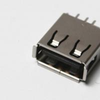 The computer does not see the flash drive: causes and solving the problem
 About Windows Update From Wannacry Encrypter Virus
 Hot browser keys
 New Mac Mini turned out to be five times more powerful than the predecessor