Radio-technical signal and their classification. Complex signals. Description of signals by means of mathematical models
2.1.1.Deterministic and random signals
Deterministic signal Is a signal, the instantaneous value of which at any moment of time can be predicted with a probability equal to one.
An example of a deterministic signal (Fig. 10) can be: sequences of pulses (the shape, amplitude and position in time of which are known), continuous signals with given amplitude-phase relationships.
Methods for specifying the MM signal: analytical expression (formula), oscillogram, spectral representation.
An example of an MM of a deterministic signal.
s (t) = S m Sin (w 0 t + j 0)
Random signal- a signal, the instantaneous value of which at any moment of time is not known in advance, but can be predicted with a certain probability, less than one.
An example of a random signal (Fig. 11) can be the voltage corresponding to human speech, music; a sequence of radio pulses at the input of the radar receiver; interference, noise.
2.1.2. Signals used in radio electronics
Continuous in magnitude (level) and continuous in time (continuous or analog) signals- take any values s (t) and exist at any moment in a given time interval (Fig. 12).
Continuous in magnitude and discrete in time signals are set at discrete time values (on a counting set of points), the value of the signal s (t) at these points takes any value in a certain interval along the ordinate.
The term "discrete" characterizes the way the signal is set on the time axis (Fig. 13).
Quantized in magnitude and continuous in time signals are set on the entire time axis, but the value s (t) can only take discrete (quantized) values (Fig. 14).
Quantized in magnitude and discrete in time (digital) signals- the values of the signal levels are transmitted in digital form (Fig. 15).
2.1.3. Pulse signals
Pulse- an oscillation that exists only within a finite period of time. In fig. 16 and 17 show a video pulse and a radio pulse.
For a trapezoidal video pulse, enter the parameters:
A is the amplitude;
t and - the duration of the video pulse;
t f - the duration of the front;
t cf - cut duration.
S р (t) = S в (t) Sin (w 0 t + j 0)
S in (t) - video pulse - an envelope for a radio pulse.
Sin (w 0 t + j 0) - filling the radio pulse.
2.1.4. Special signals
Switch-on function (single function(fig. 18) or Heaviside function) describes the process of transition of some physical object from "zero" to "single" state, and this transition occurs instantly.
Delta function (Dirac function) is a pulse, the duration of which tends to zero, while the pulse height increases indefinitely. It is customary to say that the function is concentrated at this point.
| | (2) |
| (3) |
Before embarking on the study of any phenomena, processes or objects, science always strives to classify them according to the largest possible number of signs. Let's make a similar attempt in relation to radio signals and interference.
Basic concepts, terms and definitions in the field of radio technical signals are established by the state standard “Radio technical signals. Terms and Definitions". Radio-technical signals are very diverse. They can be classified according to a variety of characteristics.
1. It is convenient to consider radio-technical signals in the form of mathematical functions given in time and physical coordinates. From this point of view, the signals are divided into one-dimensional and multidimensional... In practice, one-dimensional signals are most common. They are usually functions of time. Multidimensional signals consist of many one-dimensional signals, and in addition, reflect their position in n- dimensional space. For example, signals carrying information about the image of an object, nature, man or animal, are functions of both time and position on the plane.
2. According to the peculiarities of the structure of the temporal representation, all radio technical signals are subdivided into analog, discrete and digital... In lecture number 1, their main features and differences from each other have already been considered.
3. According to the degree of availability of a priori information, it is customary to divide the entire variety of radio-technical signals into two main groups: deterministic(regular) and random signals. Radio-technical signals are called deterministic, the instantaneous values of which are reliably known at any time. An example of a deterministic radio engineering signal is a harmonic (sinusoidal) oscillation, a sequence or burst of pulses, the shape, amplitude and temporal position of which are known in advance. In fact, a deterministic signal does not carry any information and almost all of its parameters can be transmitted via a radio communication channel with one or more code values. In other words, deterministic signals (messages) essentially do not contain information, and there is no point in transmitting them. They are usually used to test communication systems, radio channels or individual devices.
Deterministic signals are subdivided into periodic and non-periodic (impulse). An impulse signal is a signal of final energy that is significantly different from zero for a limited time interval commensurate with the time of completion of the transient in the system for which this signal is intended to act. Periodic signals are harmonic, that is, containing only one harmonic, and polyharmonic, the spectrum of which consists of many harmonic components. Harmonic signals are signals described by a sine or cosine function. All other signals are called polyharmonic.
Random signals- these are signals, the instantaneous values of which are unknown at any moments of time and cannot be predicted with a probability equal to one. Paradoxical as it may seem at first glance, only a random signal can be a signal carrying useful information. The information in it is embedded in a variety of amplitude, frequency (phase) or code changes in the transmitted signal. In practice, any radio signal containing useful information should be considered random.
4. In the process of transmitting information, signals can be subjected to one or another transformation. This is usually reflected in their name: signals modulated, demodulated(detected), coded (decoded), reinforced, detainees, discretized, quantized and etc.
5. According to the purpose that the signals have in the process of modulation, they can be divided into modulating(the primary signal that modulates the carrier waveform) or modulated(bearing vibration).
6. By belonging to one or another type of information transmission systems are distinguished telephone, telegraph, broadcasting, television, radar, managing directors, measuring and other signals.
Let us now consider the classification of radio-technical interference. Under radio interference understand a random signal that is homogeneous with a useful one and acts simultaneously with it. For radio communication systems, interference is any accidental effect on a useful signal that impairs the fidelity of the transmitted messages. Classification of radio-technical interference is also possible by a number of signs.
1. At the place of occurrence, the interference is divided into external and internal... Their main types have already been discussed in lecture number 1.
2. Depending on the nature of the interaction of the interference with the signal, one distinguishes additive and multiplicative interference. Interference is called additive, which is added to the signal. Interference is called multiplicative interference, which is multiplied with the signal. In real communication channels, both additive and multiplicative interference usually take place.
3. According to its main properties, additive noise can be divided into three classes: spectrum-lumped(narrowband interference), impulse noise(centered in time) and fluctuation noise(fluctuation noise), not limited in time or spectrum. Spectrum-centered interference is called interference, the bulk of the power of which is located in separate parts of the frequency range, less than the bandwidth of the radio engineering system. Pulse noise is a regular or chaotic sequence of pulsed signals that are homogeneous with a useful signal. Sources of such interference are digital and switching elements of radio circuits or devices operating near them. Pulsed and lumped disturbances are often referred to as tips.
There is no fundamental difference between signal and interference. Moreover, they exist in unity, although they are opposite in their action.
Random processes
As mentioned above, a distinctive feature of a random signal is that its instantaneous values are not predictable in advance. Almost all real random signals and noises are chaotic functions of time, the mathematical models of which are random processes studied in the discipline of statistical radio engineering. By a random process it is customary to call a random function of an argument t, where t the current time. A random process is denoted by the capital letters of the Greek alphabet,,. Another designation is also acceptable if it is agreed in advance. A specific type of random process that is observed during an experiment, for example, on an oscilloscope, is called implementation this random process. Type of specific implementation x (t) can be specified by a certain functional dependence of the argument t or schedule.
Depending on whether continuous or discrete values take an argument t and implementation X, there are five main types of random processes. Let us explain these types with examples.
A continuous random process is characterized by the fact that t and X are continuous quantities (Fig. 2.1, a). Such a process, for example, is the noise at the output of a radio receiver.
A discrete random process is characterized by the fact that t is a continuous quantity, and X- discrete (Fig. 2.1, b). The transition from to occurs at any time. An example of such a process is a process that characterizes the state of a queuing system when the system jumps at arbitrary times t passes from one state to another. Another example is the result of quantizing a continuous process by level only.

A random sequence is characterized by the fact that t is discrete and X- continuous quantities (Fig. 2.1, c). As an example, you can point to time samples at specific points in time from a continuous process.
A discrete random sequence is characterized by the fact that t and X are discrete quantities (Fig. 2.1, d). Such a process can be obtained by level quantization and time sampling. These are the signals in digital communication systems.
A random stream is a sequence of points, delta functions or events (Fig. 2.1, e, g) at random times. This process is widely used in the theory of reliability, when the flow of faults in electronic equipment is considered as a random process.
Questions for the state exam
on the course "Digital Signal Processing and Signal Processors"
(Korneev D.A.)
Distance learning
Signal classification, energy and power of signals. Fourier series. Sine-cosine form, real form, complex form.
CLASSIFICATION OF SIGNALS USED IN RADIO ENGINEERING
From an informational point of view, signals can be divided into deterministic and random.
Deterministic any signal is called, the instantaneous value of which at any moment of time can be predicted with a probability of one. Examples of deterministic signals are pulses or bursts of pulses, the shape, amplitude and position in time of which are known, as well as a continuous signal with specified amplitude and phase relationships within its spectrum.
TO random include signals whose instantaneous values are not known in advance and can be predicted only with a certain probability less than one. Such signals are, for example, an electric voltage corresponding to speech, music, a sequence of characters of a telegraph code when transmitting a non-repeating text. Random signals also include a sequence of radio pulses at the input of a radar receiver, when the amplitudes of the pulses and the phases of their high-frequency filling fluctuate due to changes in propagation conditions, target position, and some other reasons. Many other examples of random signals can be cited. Essentially, any signal that carries information should be considered random.
The deterministic signals listed above, "fully known", no longer contain information. In the following, such signals will often be referred to as wobble.
Along with useful random signals, in theory and practice, one has to deal with random interference - noise. The noise level is the main factor limiting the information transfer rate for a given signal.

Analog signal Discrete signal


Quantized signal Digital signal

Rice. 1.2. Signals arbitrary in magnitude and time (a), arbitrary in magnitude and discrete in time (b), quantized in magnitude and continuous in time (c), quantized in magnitude and discrete in time (d)
Meanwhile, signals from the source of messages can be both continuous and discrete (digital). In this regard, the signals used in modern radio electronics can be divided into the following classes:
arbitrary in size and continuous in time (Fig. 1.2, a);
arbitrary in size and discrete in time (Fig. 1.2, b);
quantized in magnitude and continuous in time (Fig. 1.2, c);
quantized in magnitude and discrete in time (Fig. 1.2, d).
First class signals (Fig. 1.2, a) are sometimes called analog, since they can be interpreted as electrical models of physical quantities, or continuous, since they are set along the time axis at an uncountable set of points. Such sets are called continuous. In this case, the signals along the ordinate axis can take any value within a certain interval. Since these signals can have discontinuities, as in Fig. 1.2, a, then, in order to avoid incorrectness in the description, it is better to designate such signals with the term continuous.
So, the continuous signal s (t) is a function of the continuous variable t, and the discrete signal s (x) is a function of the discrete variable x, which takes only fixed values. Discrete signals can be generated directly by a source of information (for example, discrete sensors in control or telemetry systems) or be generated as a result of discretization of continuous signals.
In fig. 1.2, b shows a signal given at discrete values of time t (on a countable set of points); the magnitude of the signal at these points can take any value within a certain interval along the ordinate (as in Fig. 1.2, a). Thus, the term discrete does not characterize the signal itself, but the way it is specified on the time axis.
The signal in Fig. 1.2, в is set on the entire time axis, but its value can only take discrete values. In such cases, one speaks of a signal quantized in terms of level.
In what follows, the term discrete will only be applied to time sampling; discreteness in terms of level will be denoted by the term quantization.
Quantization is used when representing signals in digital form using digital coding, since the levels can be numbered with numbers with a finite number of digits. Therefore, the signal discrete in time and quantized in level (Fig. 1.2, d) will be referred to as digital in the following.
Thus, we can distinguish between continuous (Fig. 1.2, a), discrete (Fig. 1.2, b), quantized (Fig. 1.2, c) and digital (Fig. 1.2, d) signals.
Each of these signal classes can be assigned to analog, discrete or digital circuits. The relationship between the type of signal and the type of circuit is shown in the functional diagram (Fig. 1.3).
When processing a continuous signal using an analog circuit, no additional signal conversions are required. When processing a continuous signal using a discrete circuit, two transformations are required: time sampling of the signal at the input of the discrete circuit and the inverse transformation, i.e., restoration of the continual structure of the signal at the output of the discrete circuit.

For arbitrary waveform s (t) = a (t) + jb (t), where a (t) and b (t) are real functions, the instantaneous signal power (energy distribution density) is determined by the expression:
w (t) = s (t) s * (t) = a 2 (t) + b 2 (t) = | s (t) | 2.
The signal energy is equal to the integral of the power over the entire interval of the signal existence. In the limit:
Е s = w (t) dt = | s (t) | 2 dt.
Essentially, instantaneous power is the power density of a signal, since power measurements are only possible through the energy released at certain intervals of non-zero length:
w (t) = (1 / Dt) | s (t) | 2 dt.
The signal s (t) is studied, as a rule, at a certain interval T (for periodic signals - within one period T), while the average signal power is:
W T (t) = (1 / T) w (t) dt = (1 / T) | s (t) | 2 dt.
The concept of average power can be extended to continuous signals, the energy of which is infinitely large. In the case of an unlimited interval T, a strictly correct determination of the average signal power is made according to the formula:
W s = w (t) dt.
The idea that any periodic function can be represented as a series of harmonically related sines and cosines was proposed by Baron Jean Baptiste Joseph Fourier (1768-1830).
Fourier series function f (x) is represented as


General information about radio signals
When transmitting information over a distance using radio engineering systems, various types of radio engineering (electrical) signals are used. Traditionally radio engineering signals are considered to be any electrical signals related to the radio band. From a mathematical point of view, any radio signal can be represented by a certain function of time u (t ), which characterizes the change in its instantaneous values of voltage (most often), current or power. According to the mathematical representation, the whole variety of radio engineering signals is usually divided into two main groups: deterministic (regular) and random signals.
Deterministic are called radio technical signals, the instantaneous values of which are reliably known at any moment of time, that is, they are predictable with a probability equal to one / 1 /. An example of a deterministic radio engineering signal is a harmonic oscillation. It should be noted that, in fact, a deterministic signal does not carry any information and almost all of its parameters can be transmitted via a radio communication channel with one or more code values. In other words, deterministic signals (messages) essentially do not contain information, and there is no point in transmitting them.
Random signals- these are signals, the instantaneous values of which at any time instant are not known and cannot be predicted with a probability equal to one / 1 /. Almost all real random signals, or most of them, are chaotic functions of time.
According to the peculiarities of the structure of the temporal representation, all radio technical signals are divided into continuous and discrete.and by the type of transmitted information: analog and digital.In radio engineering, pulse systems are widely used, the operation of which is based on the use of discrete signals. One of the types of discrete signals is digital signal / 1 /. In it, discrete signal values are replaced by numbers, most often implemented in a binary code, which represent high (unit) and low (zero) voltage potential levels.
Functions describing signals can take both real and complex values. Therefore, in radio engineering, one speaks of real and complex signals. Application of this or that form of signal description is a matter of mathematical convenience.
Spectrum concept
Direct analysis of the effect of signals of complex shape on radio circuits is very difficult and generally not always possible. Therefore, it makes sense to represent complex signals as the sum of some simple elementary signals. The principle of superposition substantiates the possibility of such a representation, asserting that in linear circuits, the effect of the total signal is equivalent to the sum of the effects of the corresponding signals separately.
Harmonics are often used as elementary signals. This choice has several advantages:
a) Decomposition into harmonics is realized quite easily by using the Fourier transform.
b) When a harmonic signal acts on any linear circuit, its shape does not change (remains harmonic). The signal frequency is also saved. Amplitude and phase vary, of course; they can be calculated relatively simply using the method of complex amplitudes.
c) In technology, resonant systems are widely used, which make it possible to experimentally separate one harmonic from a complex signal.
Representing a signal as a sum of harmonics given by frequency, amplitude, and phase is called signal spectrum decomposition.
The harmonics that make up the signal are given in trigonometric or imaginary indicative form.
Before embarking on the study of any phenomena, processes or objects, science always strives to classify them according to the largest possible number of signs. Let's make a similar attempt in relation to radio signals and interference.
Basic concepts, terms and definitions in the field of radio technical signals are established by the state standard “Radio technical signals. Terms and Definitions". Radio-technical signals are very diverse. They can be classified according to a variety of characteristics.
1. It is convenient to consider radio-technical signals in the form of mathematical functions given in time and physical coordinates. From this point of view, the signals are divided into one-dimensional and multidimensional... In practice, one-dimensional signals are most common. They are usually functions of time. Multidimensional signals consist of many one-dimensional signals, and in addition, reflect their position in n- dimensional space. For example, signals carrying information about the image of an object, nature, man or animal, are functions of both time and position on the plane.
2. According to the peculiarities of the structure of the temporal representation, all radio technical signals are subdivided into analog, discrete and digital... In lecture number 1, their main features and differences from each other have already been considered.
3. According to the degree of availability of a priori information, it is customary to divide the entire variety of radio-technical signals into two main groups: deterministic(regular) and random signals. Radio-technical signals are called deterministic, the instantaneous values of which are reliably known at any time. An example of a deterministic radio engineering signal is a harmonic (sinusoidal) oscillation, a sequence or burst of pulses, the shape, amplitude and temporal position of which are known in advance. In fact, a deterministic signal does not carry any information and almost all of its parameters can be transmitted via a radio communication channel with one or more code values. In other words, deterministic signals (messages) essentially do not contain information, and there is no point in transmitting them. They are usually used to test communication systems, radio channels or individual devices.
Deterministic signals are subdivided into periodic and non-periodic (impulse). An impulse signal is a signal of final energy that is significantly different from zero for a limited time interval commensurate with the time of completion of the transient in the system for which this signal is intended to act. Periodic signals are harmonic, that is, containing only one harmonic, and polyharmonic, the spectrum of which consists of many harmonic components. Harmonic signals are signals described by a sine or cosine function. All other signals are called polyharmonic.
Random signals- these are signals, the instantaneous values of which are unknown at any moments of time and cannot be predicted with a probability equal to one. Paradoxical as it may seem at first glance, only a random signal can be a signal carrying useful information. The information in it is embedded in a variety of amplitude, frequency (phase) or code changes in the transmitted signal. In practice, any radio signal containing useful information should be considered random.
4. In the process of transmitting information, signals can be subjected to one or another transformation. This is usually reflected in their name: signals modulated, demodulated(detected), coded (decoded), reinforced, detainees, discretized, quantized and etc.
5. According to the purpose that the signals have in the process of modulation, they can be divided into modulating(the primary signal that modulates the carrier waveform) or modulated(bearing vibration).
6. By belonging to one or another type of information transmission systems are distinguished telephone, telegraph, broadcasting, television, radar, managing directors, measuring and other signals.
Let us now consider the classification of radio-technical interference. Under radio interference understand a random signal that is homogeneous with a useful one and acts simultaneously with it. For radio communication systems, interference is any accidental effect on a useful signal that impairs the fidelity of the transmitted messages. Classification of radio-technical interference is also possible by a number of signs.
1. At the place of occurrence, the interference is divided into external and internal... Their main types have already been discussed in lecture number 1.
2. Depending on the nature of the interaction of the interference with the signal, one distinguishes additive and multiplicative interference. Interference is called additive, which is added to the signal. Interference is called multiplicative interference, which is multiplied with the signal. In real communication channels, both additive and multiplicative interference usually take place.
3. According to its main properties, additive noise can be divided into three classes: spectrum-lumped(narrowband interference), impulse noise(centered in time) and fluctuation noise(fluctuation noise), not limited in time or spectrum. Spectrum-centered interference is called interference, the bulk of the power of which is located in separate parts of the frequency range, less than the bandwidth of the radio engineering system. Pulse noise is a regular or chaotic sequence of pulsed signals that are homogeneous with a useful signal. Sources of such interference are digital and switching elements of radio circuits or devices operating near them. Pulsed and lumped disturbances are often referred to as tips.
There is no fundamental difference between signal and interference. Moreover, they exist in unity, although they are opposite in their action.
 Analysis of legacy code when the source code is lost: do or not?
 Windows does not load after installing updates Laptop does not turn on after updating windows 10
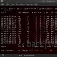 How to crack a password: an overview of the most common methods
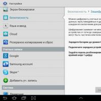 Disable encryption on the tablet
 Creation of a light bulb. Edison's light bulb. Who Invented the First Light Bulb? Why did Edison get all the glory? Incandescent lamp device change history
 How to quickly find your phone on google, wherever it is
 The electric incandescent lamp was invented in russia