7 segment indicator 4 digits arduino. Arduino and four-digit seven-segment indicator. Managing seven-segment indicators
Connection diagram for a single-digit seven-segment indicator
Connection diagram for a multi-digit seven-segment indicator
Digital information display device. This is the simplest implementation of an indicator that can display Arabic numerals. More complex multi-segment and matrix indicators are used to display letters.
As its name says, it consists of seven display elements (segments) that turn on and off separately. By including them in different combinations, they can be used to create simplified images of Arabic numerals.
The segments are designated by letters A through G; eighth segment - decimal point
(decimal point, DP), designed to display fractional numbers.
Occasionally, letters are displayed on the seven-segment indicator.


They come in a variety of colors, usually white, red, green, yellow and blue. In addition, they can be of different sizes.
Also, the LED indicator can be single-digit (as in the figure above) or multi-digit. Basically, one-, two-, three- and four-digit LED indicators are used in practice:

 In addition to ten digits, seven-segment indicators are capable of displaying letters. But few letters have an intuitive seven-segment representation.
In Latin: capital A, B, C, E, F, G, H, I, J, L, N, O, P, S, U, Y, Z, lowercase a, b, c, d, e, g , h, i, n, o, q, r, t, u.
In Cyrillic: A, B, V, G, g, E, i, N, O, o, P, p, R, S, s, U, Ch, Y (two digits), b, E/Z.
Therefore, seven-segment indicators are used only to display simple messages.
In total, the seven-segment LED indicator can display 128 characters:

A typical LED indicator has nine leads: one goes to the cathodes of all segments, and the other eight go to the anode of each segment. This scheme is called "common cathode circuit", there are also schemes with common anode(then it's the other way around). Often, not one, but two common terminals are made at different ends of the base - this simplifies the wiring without increasing the dimensions. There are also so-called “universal” ones, but I personally have not encountered such ones. In addition, there are indicators with a built-in shift register, which greatly reduces the number of microcontroller port pins involved, but they are much more expensive and are rarely used in practice. And since the immensity cannot be grasped, we will not consider such indicators for now (but there are also indicators with a much larger number of segments, matrix ones).
Multi-digit LED indicators often work on a dynamic principle: the outputs of the segments of the same name of all digits are connected together. To display information on such an indicator, the control microcircuit must cyclically supply current to the common terminals of all digits, while current is supplied to the segment terminals depending on whether a given segment is lit in a given digit.


Connecting a one-digit seven-segment indicator to a microcontroller
The diagram below shows how a single-digit seven-segment indicator is connected to the microcontroller.
It should be taken into account that if the indicator with COMMON CATHODE, then its common output is connected to "earth", and the segments are ignited by feeding logical unit to the port output.
If the indicator is COMMON ANODE, then it is supplied to its common wire "plus" voltage, and the segments are ignited by switching the port output to the state logical zero.
 Indication in a single-digit LED indicator is carried out by applying a binary code to the pins of the microcontroller port of the corresponding digit of the corresponding logical level (for indicators with OK - logical ones, for indicators with OA - logical zeros).
Current limiting resistors may or may not be present in the diagram. It all depends on the supply voltage supplied to the indicator and the technical characteristics of the indicators. If, for example, the voltage supplied to the segments is 5 volts, and they are designed for an operating voltage of 2 volts, then current-limiting resistors must be installed (to limit the current through them for an increased supply voltage and not burn not only the indicator, but also the microcontroller port).
It is very easy to calculate the value of current-limiting resistors, using the grandfather’s formula Ohm.
For example, the characteristics of the indicator are as follows (taken from the datasheet):
— operating voltage — 2 volts
— operating current — 10 mA (=0.01 A)
— supply voltage 5 volts
Formula for calculation:
R= U/I (all values in this formula must be in Ohms, Volts and Amps)
R= (supply voltage - operating voltage)/operating current
R= (5-2)/0.01 = 300 Ohm
Connection diagram for a multi-digit seven-segment LED indicator Basically the same as when connecting a single-digit indicator. The only thing is that control transistors are added in the cathodes (anodes) of the indicators:

It is not shown in the diagram, but between the bases of the transistors and the pins of the microcontroller port, it is necessary to include resistors, the resistance of which depends on the type of transistor (the resistor values are calculated, but you can also try using resistors with a nominal value of 5-10 kOhm).
Indication by discharges is carried out dynamically:
— the binary code of the corresponding digit is set at the outputs of the PB port for the 1st digit, then the logical level is applied to the control transistor of the first digit
— the binary code of the corresponding digit is set at the outputs of the PB port for the 2nd digit, then the logical level is applied to the control transistor of the second digit
— the binary code of the corresponding digit is set at the outputs of the PB port for the 3rd digit, then the logical level is applied to the control transistor of the third digit
- so in a circle
In this case, it is necessary to take into account:
— for indicators with OK control transistor structure is used NPN(controlled by logical unit)
- for indicator with OA- structure transistor PNP(controlled by logic zero)
This article continues the series of my publications about the organization of dynamic indication on PIC microcontrollers and LED indicators. Here are links to previous posts:
Table of operation of the proposed algorithm (an indicator with a common cathode is used, the first column shows the register outputs combined with the indicator digits) according to the connection diagram given below.
In each of the interrupts with an interval of 2 ms (in this case from the TMR0 timer), one stage of dynamic indication (DI) is prepared according to an algorithm that consists of five phases of register and indicator control.
2nd phase: The positive edge at pin 12 of the register (ST_CP) writes the zero state of the register to the output latch. Here and further, before the start of the indication, the indicator is extinguished by zero potential on the segments.
3rd phase: by controlling register pins 14 (DS - data) and 11 (SH_CP - clock), the code for controlling the segments is written into it.
4th phase: with a positive drop at pin 12 of the register, data from the register is written to the output latch, and, due to the positive levels on the bits, the indicator remains off.
5th phase: here the required code is supplied to the outputs of the indicator digits, and then the actual indication occurs.
If the circuit uses one 4-digit indicator, then for proper operation it must be set to OK. If you need to control 8 bits, then 8 ports of the MK are used, while the remaining 4 ports simply control the bits (in phase 4 they should have a high level). It is worth noting that in this case it is possible to use indicators with both OK and OA, connecting segments or digits to the register, respectively (for the reasons stated below, in the first case it is preferable to organize DI segment-by-segment, and in the second - bit-by-bit).
Using this method, you can connect two four-bit indicators to the PIC16F676 MCU using one shift register, while leaving as many as four free ports for use. For example, for such a connection, people used the combination of DI and analog input functions in some MK ports (in my opinion, an extremely dubious decision), which led to a significant complication of the circuit and to some limitations, which the authors warn about. Using my connection diagram, everything would be solved simply and beautifully - separate inputs, separate indications, plus two more ports (including MCLR) for buttons.
To test this control method, the following simple circuit is proposed on the PIC12F629 MCU and the FYQ3641A indicator, which alternately displays the word “test” and the number 1234 on the indicator.

Here it was decided to use a segment-by-segment DI (one segment is turned on at each moment, and there is a code on the bit pins, where in each bit: 0 - if this segment should be lit in a given bit and 1 - otherwise), in which peak currents are transferred to the register . Why? There are two reasons for this: first, the maximum load capacity of the 74HC595 outputs is 35 mA versus 25 mA for PIC controllers; the second and main thing is that a current close to the limit through the output port of the MK can theoretically raise its output potential to the level of switching the register inputs, which would lead to errors in operation. And so, currents of 6-7 mA flow into the MK ports and the potentials at the outputs certainly do not exceed TTL levels.
As mentioned above, the interruption interval is 2 ms, which corresponds to the indicator refresh rate of 64 Hz and its glow is quite comfortable for the eye.
This DI method, among other things, made it possible to halve the number of current-limiting resistors (R2-R5).
The device is assembled on a so-called “solderless” breadboard.

The indicator can be replaced with any of the 3641A series.
The circuit is powered by a stabilized 5 V source. I used a special stabilizer board designed for use with the breadboard mentioned above.
The MK control program is written in C language and translated in the environment.
Code in MikroC, project, HEX file in the application.
To use this connection method in commercial developments, please contact me.
List of radioelements
| Designation | Type | Denomination | Quantity | Note | Shop | My notepad |
|---|---|---|---|---|---|---|
| DD1 | MK PIC 8-bit | PIC12F629 | 1 | To notepad | ||
| DD2 | Register | 74HC595 | 1 | To notepad | ||
| H.L. | Indicator | FYQ3641 | 1 | To notepad | ||
| R1 | Resistor | 30 kOhm | 1 | To notepad | ||
| R2 | Resistor | 430 Ohm | 1 | To notepad | ||
| R3 | Resistor | 430 Ohm | 1 |

Surely you have already seen the “eight” indicators. This is a seven-segment LED indicator, which serves to display numbers from 0 to 9, as well as the decimal point ( D.P.- Decimal point) or comma.
Structurally, this product is an assembly of LEDs. Each LED in the assembly illuminates its own sign segment.
Depending on the model, the assembly may consist of 1 - 4 seven-segment groups. For example, the ALS333B1 indicator consists of one seven-segment group, which is capable of displaying only one digit from 0 to 9.
But the KEM-5162AS LED indicator already has two seven-segment groups. It is two-digit. The following photo shows different seven-segment LED indicators.

There are also indicators with 4 seven-segment groups - four-digit (pictured - FYQ-5641BSR-11). They can be used in homemade electronic watches.

How are seven-segment indicators indicated on the diagrams?
Since the seven-segment indicator is a combined electronic device, its image on the diagrams differs little from its appearance.

One has only to pay attention to the fact that each pin corresponds to a specific sign segment to which it is connected. There is also one or more terminals of a common cathode or anode, depending on the model of the device.
Features of seven-segment indicators.
Despite the apparent simplicity of this part, it also has its own peculiarities.
Firstly, seven-segment LED indicators come with a common anode and a common cathode. This feature should be taken into account when purchasing it for a homemade design or device.
Here, for example, is the pinout of the 4-digit indicator already familiar to us FYQ-5641BSR-11.

As you can see, the anodes of the LEDs of each digit are combined and output to a separate pin. The cathodes of LEDs that belong to the sign segment (for example, G), connected together. A lot depends on what kind of connection diagram the indicator has (with a common anode or cathode). If you look at the circuit diagrams of devices using seven-segment indicators, it will become clear why this is so important.
In addition to small indicators, there are large and even very large ones. They can be seen in public places, usually in the form of wall clocks, thermometers, and informers.
To increase the size of the numbers on the display and at the same time maintain sufficient brightness of each segment, several LEDs are used, connected in series. Here is an example of such an indicator - it fits in the palm of your hand. This FYS-23011-BUB-21.

One segment of it consists of 4 LEDs connected in series.

To illuminate one of the segments (A, B, C, D, E, F or G), you need to apply a voltage of 11.2 volts to it (2.8V for each LED). You can do less, for example, 10V, but the brightness will also decrease. The exception is the decimal point (DP), its segment consists of two LEDs. It only needs 5 - 5.6 volts.

Two-color indicators are also found in nature. For example, red and green LEDs are built into them. It turns out that there are, as it were, two indicators built into the case, but with LEDs of different colors. If you apply voltage to both LED circuits, you can get a yellow glow from the segments. Here is a wiring diagram for one of these two-color indicators (SBA-15-11EGWA).

If you connect pins 1 ( RED) and 5 ( GREEN) to “+” power supply through key transistors, you can change the color of the displayed numbers from red to green. And if you connect pins 1 and 5 at the same time, the glow color will be orange. This is how you can play around with indicators.
Management of seven-segment indicators.
To control seven-segment indicators in digital devices, shift registers and decoders are used. For example, a widely used decoder for controlling indicators of the ALS333 and ALS324 series is a microcircuit K514ID2 or K176ID2. Here's an example.
And to control modern imported indicators, shift registers are usually used 74HC595. In theory, the display segments can be controlled directly from the microcontroller outputs. But such a circuit is rarely used, since this requires using quite a few pins of the microcontroller itself. Therefore, shift registers are used for this purpose. In addition, the current consumed by the LEDs of the sign segment may be greater than the current that the ordinary output of the microcontroller can provide.
To control large seven-segment indicators, such as the FYS-23011-BUB-21, specialized drivers are used, for example, a microcircuit MBI5026.
What's inside the seven-segment indicator?
Well, a little something tasty. Any electronics engineer would not be one if he were not interested in the “insides” of radio components. This is what's inside the ALS324B1 indicator.

The black squares on the base are LED crystals. Here you can also see the gold jumpers that connect the crystal to one of the pins. Unfortunately, this indicator will no longer work, since these same jumpers were torn off. But we can see what is hidden behind the decorative panel of the scoreboard.
Connecting a 7-segment display to an Arduino is a great entry-level project to get to know your Arduino board better. But it's quite easy to do. Therefore, we will complicate the task somewhat and connect a four-digit seven-segment indicator.
In this case, we will use a four-digit LED indicator module with a common cathode.
Each segment in the indicator module is multiplexed, meaning it shares one anode connection point with other segments of its discharge. And each of the four bits in the module has its own connection point with a common cathode. This allows each digit to be turned on or off independently. Additionally, this multiplexing method allows the microcontroller to use only eleven or twelve pins instead of thirty-two.
The LED segments of the indicator require the connection of current-limiting resistors when powered from 5 V on the logic pin. The resistor value is usually taken between 330 and 470 ohms. It is also recommended to use transistors to provide additional current, since each pin of the microcontroller can supply a maximum of 40 mA. If you turn on all the discharge segments (number 8), the current consumption will exceed this limit. The figure below shows a connection diagram for a four-digit seven-segment indicator using current-limiting resistor transistors.

The following are diagrams for connecting the indicator to the Arduino pins. BC547 bipolar npn transistors are used here. A 10 KOhm potentiometer connected to the input of the A0 board allows you to change the value displayed on the indicator from 0 to 1023.


On the Arduino board, digital outputs D2-D8 in this case are used to control segments “a” to “g”, and digital outputs D9-D12 are used to control bits D0 to D3. It should be noted that in this example the dot is not used, but in the sketch below it is possible to use it. Pin D13 of the Arduino board is reserved for controlling the point segment.

Below is the code that allows you to control a four-digit segment indicator using an Arduino board. In it, the numeral array specifies the codes of numbers from 0 to 9 in binary form. This sketch supports both indicators with a common cathode (by default) and indicators with a common anode (to do this, you need to uncomment one line at the end of the sketch).
// bits representing segments A through G (and dots), for numbers 0-9 const int numeral = ( //ABCDEFG /dp B11111100, // 0 B01100000, // 1 B11011010, // 2 B11110010, // 3 B01100110, // 4 B10110110, // 5 B00111110, // 6 B11100000, // 7 B11111110, // 8 B11100110, // 9 ); // pins for a point and each segment // DP,G,F,E,D,C,B,A const int segmentPins = ( 13,8,7,6,5,4,3,2 ); const int nbrDigits= 4; // number of digits of the LED indicator // digits 0 1 2 3 const int digitPins = ( 9,10,11,12 ); void setup() ( for(int i=0; i< 8; i++) { pinMode(segmentPins[i], OUTPUT); // устанавливаем выводы для сегментов и точки на выход } for(int i=0; i < nbrDigits; i++) { pinMode(digitPins[i], OUTPUT); } } void loop() { int value = analogRead(0); showNumber(value); } void showNumber(int number) { if(number == 0) { showDigit(0, nbrDigits-1) ; // отображаем 0 в правом разряде } else { // отображаем значение, соответствующее каждой цифре // крайняя левая цифра 0, правая на единицу меньше, чем число позиций for(int digit = nbrDigits-1; digit >= 0; digit--) ( if(number > 0) ( showDigit(number % 10, digit) ; number = number / 10; ) ) ) ) // Display the specified number on this digit of the 7-segment indicator void showDigit(int number, int digit) ( digitalWrite(digitPins, HIGH); for(int segment = 1; segment< 8; segment++) { boolean isBitSet = bitRead(numeral, segment); // isBitSet будет истинным, если данный бит будет 1 // isBitSet = ! isBitSet; // опционально // раскомментируйте опциональную строчку выше для индикатора с общим анодом digitalWrite(segmentPins, isBitSet); } delay(5); digitalWrite(digitPins, LOW); }
New articles
● Project 7: 4-digit matrix of 7-segment indicators. Making a dynamic display
In this experiment we will look at the operation of Arduino with a 4-bit seven-segment matrix. Let's get an idea of dynamic display, which allows you to use the same Arduino pins when displaying information on several seven-segment indicators.
Required components:
The 4-digit matrix of seven-segment indicators consists of four seven-segment indicators and is designed to simultaneously display 4 digits on the matrix; it is also possible to display a decimal point. The circuit of a 4-bit matrix on 7-segment indicators is shown in Fig. 7.1.
Rice. 7.1. Scheme of a 4-bit matrix on 7-segment indicators
To output a number, you need to light the necessary LEDs on pins A-G and DP and select the desired matrix by applying LOW to pin 6, 8, 9 or 12.
Let's connect the matrix contacts to the Arduino board and output numbers to various bits of the matrix. To connect we need 12 Arduino pins. The connection diagram for connecting a 4-bit matrix to the Arduino board is shown in Fig. 7.2. When connecting contacts, 510 Ohm limiting resistors are used.

Rice. 7.2. Connection diagram for 4-bit matrix to Arduino
Let's write a sketch of sequential output of numbers (0-9) to an arbitrary register of the matrix. To select a random value from the range, we will use the random() function. The numbers array stores values corresponding to the data for displaying digits 0-9 (the most significant bit of the byte corresponds to the label of segment A of the indicator, and the low-order one to segment G), the pins array contains the contact values for segments A-G and DP, the pindigits array contains the contact values for selecting a matrix digit. The contents of the sketch are shown in Listing 7.1.
// variable to store the value of the current digit int number=0 ; // seven-segment indicator int digit=0 ; void setup()( for (int i=0 ;i<8
;i++)
pinMode(pins[i],OUTPUT);
for
(int
i=0
;i<4
;i++)
{pinMode(pindigits[i],OUTPUT);
digitalWrite(pindigits[i],HIGH);
}
}
void loop()( number=(number+1 )%10 ; showNumber(number); // DS for (int i=0 ;i<4
;i++)
digitalWrite(pindigits[i],HIGH);
digit=random(0
,4
);
digitalWrite(pindigits,LOW);
delay(3000
);
}
void showNumber( int num)( for (int i=0 ;i<7
;i++)
{
if
(bitRead(numbers,7
-i)==HIGH) // light the segment // extinguish the segment digitalWrite(pins[i],LOW); ) )
Connection order:
1. Connect a seven-segment indicator according to the diagram in Fig. 7.3.
2. Load the sketch from Listing 7.2 onto the Arduino board.
// list of Arduino pins to connect to bits a-g // seven-segment indicator int pins=(9 ,13 ,4 ,6 ,7 ,10 ,3 ,5 ); // values to display numbers 0-9 byte numbers = ( B11111100, B01100000, B11011010, B11110010, B01100110, B10110110, B10111110, B11100000, B11111110, B11110110); // variable for storing and processing the current value int number=0 ; int number1=0 ; int number2=0 ; // seven-segment indicator int pindigits=(2 ,8 ,11 ,12 ); // variable to store the current digit int digit=0 ; // to measure 100 ms unsigned long millis1=0 ; // mode 1 - stopwatch is running mode=0 ; const int BUTTON=14 ; // Pin 14(A0) for connecting the button int tekButton = LOW; // Variable to save the current state of the button int prevButton = LOW; // Variable to save the previous state// to the buttons boolean ledOn = false ; // Current state of the LED (on/off) void setup(){ // Configure the button pin as an input pinMode(BUTTON, INPUT); // Configure pins as outputs for (int i=0 ;i<8 ;i++) pinMode(pins[i],OUTPUT); for (int i=0 ;i<4 ;i++) {pinMode(pindigits[i],OUTPUT); digitalWrite(pindigits[i],HIGH); } } void loop()( tekButton = debounce(prevButton); if (prevButton == LOW && tekButton == HIGH) // if pressed... ( mode=1 -mode; // change mode if (mode==1 ) number=0 ; ) if (millis()-millis1>=100 && mode==1 ) (millis1=millis1+100 ; number=number+1 ; if (number==10000 ) number=0 ; ) number1=number; for (int i=0 ;i<4 ;i++) { number2=number1%10 ; number1=number1/10 ; showNumber(number2,i); for (int j=0 ;j<4 ;j++) digitalWrite(pindigits[j],HIGH); digitalWrite(pindigits[i],LOW); delay(1 ); } } // function for displaying numbers on a seven-segment indicator void showNumber( int num,int dig)( for (int i=0 ;i<8 ;i++) { if (bitRead(numbers,7 -i)==HIGH) // light the segment digitalWrite(pins[i],HIGH); else // extinguish the segment digitalWrite(pins[i],LOW); ) if (dig==1 ) // decimal point for second digit digitalWrite(pins,HIGH); ) // Bounce smoothing function. Accepts as // argument the previous state of the button and returns the actual one. boolean debounce ( boolean last)( boolean current = digitalRead(BUTTON); // Read the state of the button, if (last != current) // if it has changed...( d elay ( 5 ) ; // let's dem 5 m s current = digitalRead(BUTTON); // read the button state return current; // return the button state } }
3. By pressing the button we start or stop the stopwatch.

 Working with sound on the Macintosh platform (Mac OS X)
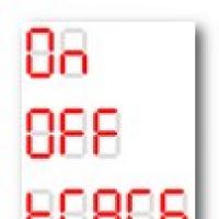 Arduino and four-digit seven-segment indicator
 Ways to check debt for telephone and Internet from Rostelecom
 How to increase computer performance for minimal money
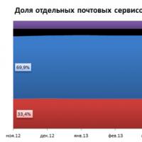 Email - where you can create it, how to register a mailbox and choose the best of the free Email services
 SHA256 – hashing algorithm
 Install CyanogenMod firmware using the CyanogenMod installer Impact on warranty