Block diagram of a data transmission network. Structural diagram of a projected computer network for enterprise automation through the introduction of CtP technology and the NetWorkFlow i2i System from Horizon. Types of cables used
The biggest problem I face when working with enterprise networks is the lack of clear and understandable logical network diagrams. In most cases, I face situations where the customer cannot provide no logic circuits or diagrams. Network diagrams (hereinafter L3-diagrams) are extremely important when solving problems or planning changes in the enterprise network. Logic diagrams are in many cases more valuable than physical wiring diagrams. Sometimes I come across "logical-physical-hybrid" schemes that are practically useless. If you do not know the logical topology of your network, you are blind... Generally, the ability to draw a logical network diagram is not a general skill. It is for this reason that I am writing this article on creating clear and understandable logical network diagrams.
What information should be presented in L3 diagrams?
In order to create a network diagram, you must have an accurate understanding of how which information must be present and on which exactly schemes. Otherwise, you will mix information and end up with another useless "hybrid" scheme. Good L3 diagrams contain the following information:- subnets
- VLAN ID (all)
- VLAN names
- network addresses and masks (prefixes)
- L3 devices
- routers, firewalls (hereinafter ITU) and VPN gateways (at least)
- the most significant servers (for example, DNS, etc.)
- ip-addresses of these servers
- logical interfaces
- routing protocol information
What information should NOT be on L3 diagrams?
The information listed below should not be on the network diagrams, because it belongs to other layers [OSI model, approx. per.] and, accordingly, should be reflected on other schemes:- all L2 and L1 information (in general)
- L2 switches (only management interface can be presented)
- physical connections between devices
Used notation
Typically, logical circuits use logical symbols. Most of them are self-explanatory. I have already seen the errors of their application, then I will allow myself to stop and give a few examples:What information is needed to create an L3 schematic?
In order to create a logical network diagram, you need the following information:- L2 (or L1) circuit- representation of physical connections between L3 devices and switches
- L3 device configurations
- L2 Device Configurations- text files or GUI access, etc.
Example
In this example, we will use a simple network. It will include Cisco switches and ITU Juniper Netscreen. We are provided with an L2 diagram, as well as configuration files for most of the devices presented. The configuration files for the ISP border routers are not provided. in real life, the ISP does not transmit such information. Below is the L2 network topology:
And here are the device configuration files. Only the necessary information is left:
asw1
!
vlan 210
name Servers1
!
vlan 220
name Servers2
!
vlan 230
name Servers3
!
vlan 240
name Servers4
!
vlan 250
name In-mgmt
!
switchport mode trunk
!
switchport mode trunk
switchport trunk encapsulation dot1q
!
interface vlan 250
ip address 192.168.10.11 255.255.255.128
!
asw2
!
vlan 210
name Servers1
!
vlan 220
name Servers2
!
vlan 230
name Servers3
!
vlan 240
name Servers4
!
vlan 250
name In-mgmt
!
interface GigabitEthernet0 / 1
switchport mode trunk
switchport trunk encapsulation dot1q
!
interface GigabitEthernet0 / 2
switchport mode trunk
switchport trunk encapsulation dot1q
!
interface vlan 250
ip address 192.168.10.12 255.255.255.128
!
ip default-gateway 192.168.10.1
asw3
!
vlan 210
name Servers1
!
vlan 220
name Servers2
!
vlan 230
name Servers3
!
vlan 240
name Servers4
!
vlan 250
name In-mgmt
!
interface GigabitEthernet0 / 1
switchport mode trunk
switchport trunk encapsulation dot1q
!
interface GigabitEthernet0 / 2
switchport mode trunk
switchport trunk encapsulation dot1q
!
interface vlan 250
ip address 192.168.10.13 255.255.255.128
!
ip default-gateway 192.168.10.1
csw1
!
vlan 200
name in-transit
!
vlan 210
name Servers1
!
vlan 220
name Servers2
!
vlan 230
name Servers3
!
vlan 240
name Servers4
!
vlan 250
name In-mgmt
!
interface GigabitEthernet0 / 1
switchport mode trunk
switchport trunk encapsulation dot1q
!
interface GigabitEthernet0 / 2
switchport mode trunk
switchport trunk encapsulation dot1q
!
switchport mode trunk
switchport trunk encapsulation dot1q
channel-group 1 mode active
!
switchport mode trunk
switchport trunk encapsulation dot1q
!
switchport mode trunk
switchport trunk encapsulation dot1q
!
switchport mode trunk
switchport trunk encapsulation dot1q
!
interface Port-channel 1
switchport mode trunk
switchport trunk encapsulation dot1q
!
interface vlan 200
ip address 10.0.0.29 255.255.255.240
standby 1 ip 10.0.0.28
!
interface vlan 210
ip address 192.168.0.2 255.255.255.128
standby 2 ip 192.168.0.1
!
interface vlan 220
ip address 192.168.0.130 255.255.255.128
standby 3 ip 192.168.0.129
!
interface vlan 230
ip address 192.168.1.2 255.255.255.128
standby 4 ip 192.168.1.1
!
interface vlan 240
ip address 192.168.1.130 255.255.255.128
standby 5 ip 192.168.1.129
!
interface vlan 250
ip address 192.168.10.2 255.255.255.128
standby 6 ip 192.168.10.1
!
csw2
!
vlan 200
name in-transit
!
vlan 210
name Servers1
!
vlan 220
name Servers2
!
vlan 230
name Servers3
!
vlan 240
name Servers4
!
vlan 250
name In-mgmt
!
interface GigabitEthernet0 / 1
switchport mode trunk
switchport trunk encapsulation dot1q
!
interface GigabitEthernet0 / 2
switchport mode trunk
switchport trunk encapsulation dot1q
channel-group 1 mode active
!
interface GigabitEthernet0 / 3
switchport mode trunk
switchport trunk encapsulation dot1q
channel-group 1 mode active
!
interface GigabitEthernet0 / 4
switchport mode trunk
switchport trunk encapsulation dot1q
!
interface GigabitEthernet0 / 5
switchport mode trunk
switchport trunk encapsulation dot1q
!
interface GigabitEthernet0 / 6
switchport mode trunk
switchport trunk encapsulation dot1q
!
interface Port-channel 1
switchport mode trunk
switchport trunk encapsulation dot1q
!
interface vlan 200
ip address 10.0.0.30 255.255.255.240
standby 1 ip 10.0.0.28
!
interface vlan 210
ip address 192.168.0.3 255.255.255.128
standby 2 ip 192.168.0.1
!
interface vlan 220
ip address 192.168.0.131 255.255.255.128
standby 3 ip 192.168.0.129
!
interface vlan 230
ip address 192.168.1.3 255.255.255.128
standby 4 ip 192.168.1.1
!
interface vlan 240
ip address 192.168.1.131 255.255.255.128
standby 5 ip 192.168.1.129
!
interface vlan 250
ip address 192.168.10.3 255.255.255.128
standby 6 ip 192.168.10.1
!
ip route 0.0.0.0 0.0.0.0 10.0.0.17
fw1
set interface ethernet0 / 1 manage-ip 10.0.0.2
set interface ethernet0 / 2 manage-ip 10.0.0.18
fw2
set interface ethernet0 / 1 zone untrust
set interface ethernet0 / 1.101 tag 101 zone dmz
set interface ethernet0 / 1.102 tag 102 zone mgmt
set interface ethernet0 / 2 zone trust
set interface ethernet0 / 1 ip 10.0.0.1/28
set interface ethernet0 / 1 manage-ip 10.0.0.3
set interface ethernet0 / 1.101 ip 10.0.0.33/28
set interface ethernet0 / 1.102 ip 10.0.0.49/28
set interface ethernet0 / 2 ip 10.0.0.17/28
set interface ethernet0 / 2 manage-ip 10.0.0.19
set vrouter trust-vr route 0.0.0.0/0 interface ethernet0 / 1 gateway 10.0.0.12
outsw1
!
vlan 100
name Outside
!
vlan 101
name DMZ
!
vlan 102
name Mgmt
!
description To-Inet-rtr1
switchport mode access
switchport access vlan 100
!
switchport mode trunk
switchport trunk encapsulation dot1q
!
switchport mode trunk
switchport trunk encapsulation dot1q
channel-group 1 mode active
!
switchport mode trunk
switchport trunk encapsulation dot1q
channel-group 1 mode active
!
interface Port-channel 1
switchport mode trunk
switchport trunk encapsulation dot1q
!
interface vlan 102
ip address 10.0.0.50 255.255.255.240
!
outsw2
!
vlan 100
name Outside
!
vlan 101
name DMZ
!
vlan 102
name Mgmt
!
interface GigabitEthernet1 / 0
description To-Inet-rtr2
switchport mode access
switchport access vlan 100
!
interface GigabitEthernet1 / 1
switchport mode trunk
switchport trunk encapsulation dot1q
!
interface GigabitEthernet1 / 3
switchport mode trunk
switchport trunk encapsulation dot1q
channel-group 1 mode active
!
interface GigabitEthernet1 / 4
switchport mode trunk
switchport trunk encapsulation dot1q
channel-group 1 mode active
!
interface Port-channel 1
switchport mode trunk
switchport trunk encapsulation dot1q
!
interface vlan 102
ip address 10.0.0.51 255.255.255.240
!
ip default-gateway 10.0.0.49
Collection of information and its visualization
Good. Now that we have all the information we need, we can start visualizing.Display process step by step
- Collection of information:
- First, let's open the configuration file (in this case ASW1).
- Let's take from there each ip-address from the interface sections. In this case, there is only one address ( 192.168.10.11 ) with mask 255.255.255.128 ... Interface name - vlan250, and the name vlan 250 is In-mgmt.
- Let's take all static routes from the config. In this case, there is only one (ip default-gateway), and it points to 192.168.10.1 .
- Display:
- Now, let's display the information we have collected. First, let's draw the device ASW1... ASW1 is a switch, so we use the switch symbol.
- Let's draw a subnet (tube). Let's give her a name In-mgmt, VLAN-ID 250 and address 192.168.10.0/25 .
- Let's connect ASW1 and the subnet.
- Insert a text field between the ASW1 and subnet characters. Let's display the name of the logical interface and the ip-address in it. In this case, the interface name will be vlan250, and the last octet of the ip-address is .11 (It is a common practice to display only the last octet of the ip-address, since the ip-address of the network is already present in the diagram).
- There is also another device on the In-mgmt network. Or at least it should be. We do not yet know the name of this device, but its IP address 192.168.10.1 ... We learned this because ASW1 points to this address as the default gateway. So let's map this device to the diagram and give it a temporary name "??". We will also add its address to the diagram - .1 (by the way, I always highlight inaccurate / unknown information in red so that looking at the diagram you can immediately understand what needs to be clarified on it).

Repeat this process step by step for each network device... Gather all the information related to IP and map in the same diagram: every ip address, every interface and every static route. In the process, your diagram will become very accurate. Make sure the devices that are mentioned but not yet known are shown in the diagram. Just like we did earlier with the address 192.168.10.1 ... Once you have completed all of the above for all known network devices, you can start figuring out the unknown information. You can use MAC and ARP tables for this (wondering if the next post is worth writing about this step in detail?).
Ultimately we will have a schema like this:

Conclusion
Drawing a logical network diagram can be very simple if you have the appropriate knowledge. It is a time consuming manual process, but it is by no means magic. Once you have an L3 network diagram, it is not difficult to keep it up to date. The benefits are well worth the effort:- you can plan changes quickly and accurately;
- solving problems takes much less time than before. Let's imagine that someone needs to solve the problem of unavailability of a service for 192.168.0.200 to 192.168.1.200. After looking at the L3 diagram, it is safe to say that the ITU is not the cause of this problem.
- You can easily follow the correctness of the ITU rules. I've seen situations where ITUs contained rules for traffic that would never have gone through this ITU. This example shows perfectly well that the logical topology of the network is unknown.
- Usually, as soon as the L3 network diagram is created, you will immediately notice which parts of the network do not have redundancy, etc. In other words, L3 topology (as well as redundancy) is just as important as physical redundancy.
Communication network architecture is one of the main characteristics that determine the composition of the network, revealing the types of its functional components, the hierarchy and the nature of their interaction.
Due to the wide variety of types of transmitted messages and signals, the propagation medium, methods and devices for switching or in routing signals and information flows, the architecture of networks in communication is classified according to the requirements Unified telecommunication network in the Russian Federation (ESE RF).
Unified telecommunication network of the Russian Federation is determined by a set of communication networks for various purposes and technologies located on the territory of the Russian Federation. 1.4.
The first level of the model is primary network(primary networks), formed on transmission systems of certain types of communication. Primary networks are divided into trunk, intrazonal and local(urban and rural). The primary network is a collection of all communication channels, regardless of the purpose and type of communication; it includes communication lines and channel-forming equipment.
Second level - secondary networks, formed on the basis of transmission channels of the primary network and switching systems that perform the functions of distributing messages to a given address. Secondary networks differ in the type of messages transmitted through them: telephone, data transmission, telegraph, newspaper transmission, sound broadcasting, television broadcasting, etc. When integrating communication networks, secondary networks turn into a single network that provides the transmission and distribution of messages of various types of communication (transmission speech, data, facsimile messages, etc.).
Rice. 1.4.
PSTN - public telephone network; STFS - telephone network; STGS - telegraph communication network; ISDN - digital networks with service integration; PD - CP - data transmission - packet switching; PD - data transmission; TV - TV broadcasting; In PG - transmission of newspapers; SRPZV - distribution networks for sound broadcasting programs; ЗВ - sound broadcasting; SRPTV - distribution networks
television broadcasting programs; AT - subscriber telegraphy
The third level of the model is communication services ensuring the provision of services to users of various types of communication.
Fourth level - user of communication services. It is determined by the type of communication (transmission of voice, telegraph and / or facsimile messages, data messages), as well as the terminal equipment available to the user.
In accordance with the functions performed, the ESE networks are divided into access networks and transport networks. Through the transport network, high-speed (broadband) streams of information are transmitted. The transport network includes trunk (intercity and international) B and zonal (regional) communication networks. The access network provides subscribers with access to the transport network; it is also called subscriber access network and on a territorial basis is a local network. This network consists of subscriber lines and terminal devices.
The generalized structural diagram of a telecommunications network includes transport layer(backbone network), access level(networkIn access) and terminal equipment of users.
Telecommunication network components:
- - backbone networks;
- - access networks;
- - terminal equipment of users;
- - information centers, or service control centers (Services Control Point, SCP).
Backbone network unites separate access networks, providing traffic transport between them via high-speed channels. In fact, B backbones refer to global communication networks (Wide Area in Network, WAN).
Access network is located at the lower level of the hierarchy of the telecommunications network and is designed to aggregate flows coming through various communication channels from client equipment in the backbone network.
The access network is a highly ramified regional network. It can be multilevel. The network elements of the lower level multiplex the information arriving through multiple subscriber channels (subscriber ends), and transmit it to the network elements of the upper level for redirecting to the elements of the backbone. The size of the access network determines the number of its layers - a small one - an access network will have one layer, a large one - several.
In a computer network terminal equipment are computers, in the telephone - telephones, in the television or radio network - in the corresponding television or radio receivers.
The terminal equipment of users can form a network that is not part of the telecommunications network. For example, a set of computers of users of an organization forms local area network
(Local Area Network, LAN). Local networks are characterized by high data transfer rates over relatively short distances.
Information Centers(service control centers) provide information network services. These centers store user information (information of direct interest to end users) and service information to help the service provider provide services to users.
User information usually contains a variety of help and news information. Such telephone network centers provide, for example, emergency police or ambulance services, as well as referral services of various organizations and enterprises - train stations, airports, shops, etc.
Service information usually includes various data of the system of authorization and authentication of users, with the help of which the organization that owns the network checks the rights of users to receive certain services. These can be billing systems used to determine fees for services provided, or databases containing user accounts and lists of services provided to users.
Networks of a particular type have their own characteristics, they may lack some elements of the generalized network, but in general their structure corresponds to that described above.
A structured cabling system is a set of switching elements (cables, connectors, cross-over panels and cabinets), as well as a technique for their joint use, which allows you to create regular, easily expandable communication structures in computer networks.
The structured cabling system is a kind of "constructor", with the help of which the network designer builds the required configuration from standard cables connected by standard connectors and switched on standard cross-over panels. If necessary, the configuration of connections can be easily changed - add a computer, segment, switch, remove unnecessary equipment, and also change the connections between computers and switches.
When building a structured cabling system, it is assumed that each workplace in the enterprise must be equipped with sockets for connecting a telephone and a computer, even if this is not necessary at that moment. That is, a good structured cabling system is redundant. This can save money in the future, as changes to the connection of new devices can be made by re-connecting existing cables.
According to the assignment, the structural diagram of the location of buildings, each of which has its own subnet, is shown in Fig. 2.1.
Figure 2.1 - Structural layout of buildings
The structural diagram of the subnets of each of the buildings is shown in Fig. 2.2 - 2.3. Since there are two 5-storey buildings, and they have the same number of switching equipment and PCs, their structural diagrams are identical.

Figure 2.2 - Block diagram of the subnet of a 5-storey building

Figure 2.3 - Block diagram of the subnet of a 4-storey building
The block diagram of the connection of subnets into one network is shown in Fig. 2.4.

Figure 2.4 - General block diagram of the network
In buildings technology - FastEthernet, between buildings - FDDI, Internet access from each building via radio.
3 Choice of equipment and cable
3.1 Selecting switches
Switch (English switch) - a device designed to connect several nodes of a computer network within one or more network segments. The switch operates at the data link layer of the OSI model. Unlike a hub, which distributes traffic from one connected device to all others, a switch only transmits data directly to the recipient. This improves network performance and security by eliminating the need for other network segments to process data that was not intended for them.
In this course project, in each room of the buildings, there are room switches - workgroup switches, on each floor - a floor switch that unites the workgroup switches of its floor, and a root switch located in the server room on the first floor, to which switches of all floors are connected.
Switching equipment (switches, routers) was selected from the manufacturer Cisco. According to Dell "Oro Group, Cisco occupies 60% of the global network equipment market, that is, more than all other competitors. This manufacturer has the widest range of all network solutions, a wide range of technologies, protocols, ideologies, both standard and and our own advanced network-wide troubleshooting capabilities built into virtually all Cisco devices.
For the best balance of price, performance and functionality, the following switch models were selected from the Cisco 300 Series, designed specifically for small businesses. The line includes a range of low-cost managed switches that provide a powerful foundation for maintaining a corporate network.
Features of the Cisco 300 Series Switches
provide the high availability and performance required for mission-critical business applications while minimizing potential downtime.
allow you to control network traffic using such modern functions as analysis of quality of service, static routing of the third level, support for IPv6.
have clear tools with a web interface; the possibility of mass deployment; similar functions in all models.
allow you to optimize energy consumption without affecting performance.
3.1.1 Workgroup Switches
According to the assignment for term paper in a 4-storey building in three rooms on each floor there are 35 computers, and in two 5-storey buildings in one room on each floor there are 31 computers, for which connection the SG300-52 switch is selected, which has 48 ports (Fig. 3.1).

Figure 3.1 - SG300-52 workgroup switch
The SG300-52 switch (price: UAH 7522), manufactured by Cisco, is equipped with 48 10/100/1000 Mbps Ethernet ports with auto-negotiation of speeds for RJ45 ports, which facilitates device installation.
This switch provides good performance and improves workgroup performance and network and host throughput, ensuring easy and flexible installation and configuration. Its compact size makes it ideal for confined desktop space; the device can also be rack-mounted. Dynamic LEDs display the switch status in real time and allow basic diagnostics of device operation.
The main technical characteristics of the SG300-52 switch are presented in Table 3.1.
Table 3.1 - Technical characteristics of the SG300-52 switch
|
Managed switch |
|
|
Interface |
4 x SFP (mini-GBIC), 48 x Gigabit Ethernet (10/100/1000 Mbps) |
|
SNMP 1, RMON 1, RMON 2, RMON 3, RMON 9, Telnet, SNMP 3, SNMP 2c, HTTP, HTTPS, TFTP, SSH, |
|
|
Routing protocol |
Static IPv4 routing, 32 routes |
|
MAC address table |
16000 entries |
|
128 MB (RAM), Flash memory - 16 MB |
|
|
Encryption algorithm | |
|
Additional features |
Up to 32 static routes and up to 32 IP interfaces DHCP Layer 3 broadcast User Datagram Protocol (UDP) Broadcast Smartports simplifies configuration and security management Built-in configuration utility, web-based access (HTTP / HTTPS) Dual protocol stack IPv6 and IPv4 Upgrade software |
|
Supported standards |
IEEE 802.3 10BASE-T Ethernet, IEEE 802.3u 100BASE-TX Fast Ethernet, IEEE 802.3ab 1000BASE-T Gigabit Ethernet, IEEE 802.3ad LACP, IEEE 802.3z Gigabit Ethernet, IEEE 802.3x Flow Control, IEEE 802.1D (STP, GARP, and GVRP), IEEE 802.1Q / p VLAN, IEEE 802.1w RSTP, IEEE 802.1s Multiple STP, IEEE 802.1X Port Access Authentication, IEEE 802.3af, IEEE |
|
Internal power supply. 120-130 VAC, 50/60 Hz, 53 W. |
|
|
Environment conditions Wednesday |
Working temperature: 0 ° C ~ 40 ° C |
|
Dimensions (WxDxH) |
440 * 260 * 44mm |
For two 5-storey buildings, in which there are 18 and 25 computers in the remaining rooms on each floor, respectively, 18 computers are selected for connection - a switch for 24 ports - SF300-24P (price: UAH 4042), and for connection 25 computers - two switches, each for 16 ports - SG300-20 (price: UAH 3023), which are presented in fig. 3.2. The remaining ports are reserved.


Figure 3.2 - Switch of the working group SF300-24P (a) and SG300-20 (b)
The SF300-24P is a 24-port managed switch for networking. These switches provide all the capabilities you need to run mission-critical business applications, protect confidential information, and optimize bandwidth for more efficient network transfers. Plug-and-play and auto-negotiation support allows the switch to automatically detect the type of device being connected (such as an Ethernet network adapter) and select the most suitable speed. LED indicators are used for cable connection control and standard diagnostics. The switch can be table-mounted or rack-mounted.
The SG300-20 switch is designed for small workgroups and has 18 10/100 / 1000BASE-TX Ethernet ports and 2 mini-GBICs. The functionality of these switches is similar to the functionality of the SF300-24P switch, since they both belong to the same Cisco 300 series.
The main technical characteristics of the SF300-24P switch are presented in Table 3.2, and the SG300-20 switch - Table. 3.3.
Table 3.2 - Technical characteristics of the SF300-24P switch
|
Managed switch |
|
|
Interfaces |
24 Ethernet 10Base-T / 100Base-TX ports - RJ-45 connector, PoE support; console management port - 9 pin D-Sub (DB-9); 4 Ethernet ports 10Base-T / 100Base-TX / 1000Base-T - RJ-45 connector, 2 ports for SFP (mini-GBIC) modules. |
|
Remote Administration Protocol | |
|
Routing protocol |
Static IPv4 routing |
|
MAC address table |
16000 entries |
|
128 MB (RAM), Flash memory - 16 MB |
|
|
Encryption algorithm | |
|
Control |
SNMP v1, v2c, and v3 Integrated RMON software agent for traffic management, monitoring and analysis Dual stack IPv6 and IPv4 Software upgrade DHCP port mirroring (options 66, 67, 82, 129 and 150) Smartports simplify security configuration and management Cloud services Other management functions: Traceroute; management through a single IP address; HTTP / HTTPS; SSH; RADIUS; DHCP client; BOOTP; SNTP; Xmodem update; cable diagnostics; ping; system log; Telnet client (SSH support) |
|
Supported standards |
IEEE 802.3 10BASE-T Ethernet IEEE 802.3u 100BASE-TX Fast Ethernet IEEE 802.3ab 1000BASE-T Gigabit Ethernet IEEE 802.3ad LACP IEEE 802.3z Gigabit Ethernet IEEE 802.3x Flow Control IEEE 802.1D (STP, GARP, and GVRP) IEEE 802.1Q / p VLAN IEEE 802.1w RSTP IEEE 802.1s Multiple STP IEEE 802.1X Port Access Authentication IEEE 802.3af IEEE 802.3at |
|
Performance |
Non-blocking switching at speeds up to 9.52 Mpps (64 bytes packet size) Switching matrix: up to 12.8 Gbps Packet buffer size: 4 MB |
|
Availability |
Auto power off on RJ-45 Gigabit Ethernet ports when no connection, re-power on when activity resumes |
Table 3.3 - Technical characteristics of the SF300-20 switch
|
Managed switch |
|
|
Interfaces |
18 Ethernet 10Base-T / 100Base-TX ports - RJ-45 connector, 2 ports for SFP (mini-GBIC) modules. |
|
Remote Administration Protocol |
SNMP 1, RMON 1, RMON 2, RMON 3, RMON 9, Telnet, SNMP 3, SNMP 2c, HTTP, HTTPS, TFTP, SSH, |
|
Routing protocol |
Static IPv4 routing |
|
MAC address table |
16000 entries |
|
128 MB (RAM), Flash memory - 16 MB, buffer size - 1 MB |
|
|
Encryption algorithm |
802.1x RADIUS, HTTPS, MD5, SSH, SSH-2, SSL / TLS |
|
Control protocols |
IGMPv1 / 2/3, SNMPv1 / 2c / 3 |
|
Supported standards |
IEEE 802.1ab, IEEE 802.1D, IEEE 802.1p, IEEE 802.1Q, IEEE 802.1s, IEEE 802.1w, IEEE 802.1x, IEEE 802.3, IEEE 802.3ab, IEEE 802.3ad, IEEE 802.3at, IEEE 802.3u, IEEE 802.3x , IEEE 802.3z |
|
Supported network protocols |
IPv4 / IPv6, HTTP, SNTP, TFTP, DNS, BOOTP, Bonjour |
|
Functional |
Support for flow control Port mirroring Channel bonding Jumbo Frames support Broadcast storm control Speed limit DHCP client Spanning tree protocol, etc. |
|
Internal power supply. 120-130 VAC, 50/60 Hz, 53 W. |
|
|
Environment conditions Wednesday |
Working temperature: 0 ° C ~ 40 ° C |
3.1.2 Floor switches
To connect the switches of the workgroups, floor switches are used, which is the SRW208G-K9 switch (price: UAH 1483), which has 8 ports (Fig. 3.3).

Figure 3.3 - Floor switch SRW208G-K9
The SRW208G-K9 switch is equipped with 8 RJ45 Fast Ethernet ports, 1 Gigabit Ethernet port and two SFP (mini-GBIC) ports that operate in auto-configuring and rate sensing mode.
The Cisco Catalyst 2960 is a series of new, intelligent fixed-configuration Ethernet switches. They provide the need for data transmission at a speed of 100 Mbit / s and 1 Gbit / s, allow the use of LAN services, for example, for data transmission networks built in corporate branches. The Catalyst 2960 family provides high data security with built-in NAC, QoS support, and high levels of system resiliency.
Key Features:
High level of security, advanced access control lists (ACL);
Network control and bandwidth optimization using QoS, differential rate limiting and ACLs.
To ensure network security, switches use a wide range of user authentication methods, data encryption technologies and organization of access control to resources based on user ID, port and MAC addresses.
Switches are easy to manage and configure
Autoconfiguration function is available via Smart ports for some specialized applications.
The main technical characteristics of this switch, manufactured by Cisco, coincide with the characteristics presented in table. 3.2. for a switch of the same company.
3.1.3 Root Switches
To connect the floor switches, root switches are used, as a switch in each building was chosen - SG300-20, which has 16 ports. This switch was also chosen as a workgroup switch, its description is presented in clause 3.1.1.
3.2 Selecting routers
Router (router) - a device that has at least two network interfaces and forwards data packets between different network segments, making forwarding decisions based on information about the network topology and certain rules set by the administrator.
Routers help reduce network congestion by dividing it into collision domains or broadcast domains, and by filtering packets. They are mainly used to combine networks of different types, often incompatible in architecture and protocols. Often, a router is used to provide access from a local network to the Internet, performing the functions of address translation and firewall.
To connect buildings into one network, a router is used, which was chosen as a Cisco 7507 series 7500 (price: UAH 121360), which has the ability to connect an FDDI module (Fig. 3.4).


Figure 3.4 - Cisco 7507 Router
This router was selected based on the FDDI module connectivity, the best value for the entire product line, and the Cisco 7500 Series Modular Routers being the most powerful Cisco routers. They meet the highest requirements for modern data transmission networks. The flexible modular architecture of this series of routers allows them to be used in large network nodes, selecting the best solutions.
The Cisco 7500 series consists of three models. The Cisco 7505 has one routing and switching processor (RSP1 = Route / Switch Processor), one power supply, and four interface processor slots (5 slots in total). The Cisco 7507 and Cisco 7513, with seven and thirteen slots, respectively, provide more bandwidth and can be equipped with two RSP2 or PSP4 and redundant power supplies. Combined with the new, redundant CyBus, the Cisco 7507/7513 routers offer unmatched performance and reliability capabilities. This is achieved through a new, distributed multiprocessor architecture that includes three elements:
Integrated Routing and Switching Processor (RSP);
New Versatile Interface Processor (VIP);
New high-speed Cisco CyBus.
In a configuration with two RSPs (Integrated Routing and Switching Processor), the Cisco 7500 distributes functions between the primary and secondary RSPs, increasing system performance, and in the event of a failure of one of the processors, the other takes over all the functions.
The Cisco 7507 Router is a modular router designed for large network backbones and works with virtually all LAN and WAN technologies and all major network protocols.
The Cisco 7507 series supports a very wide range of connections, including Ethernet, Token Ring, FDDI, Serial, HSSI, ATM, Channelized T1, Fractionalized E1 (G.703 / G.704), ISDN PRI, Channel Interface for IBM mainframes.
The network interfaces are located on modular processors that provide a direct connection between the high-speed Cisco Extended Bus (CxBus) and the external network. Seven slots are available for interface processors in the Cisco 7507. Hot-swappable capability allows CxBus processor modules to be added, replaced, or removed without interrupting the network. Standard Flash memory is used to store information. All models come with a standard 19 "rack mount kit.
There are the following communication interface modules:
Ethernet Intelligent Link Interface - 2/4 Ethernet ports with high-speed filtering (29000 bps), Transparent Bridging and Spanning Tree algorithms, configurable using the Optivity system;
Token Ring Intelligent Link Interface - 2/4 ports Token Ring 4/16 Mbps;
FDDI Intelligent Link Interface - 2 ports supporting two SAS connections or one DAS connection, filtering at speeds up to 500,000 p / s;
ATM Intelligent Link Interface.
3.3 Cable selection
Cable is a construction of one or several conductors (cores) isolated from each other, or optical fibers, enclosed in a sheath. In addition to the actual conductors and insulation, it may contain a screen, load-bearing elements and other structural elements. The main purpose is the transmission of a high-frequency signal in various fields of technology: for cable television systems, for communication systems, aviation, space technology, computer networks, household appliances, etc. restrictions on the total length of the network, and there are restrictions on the length of physical segments connecting neighboring devices (switch-adapter and switch-switch).
On assignment, Fast Ethernet technology with 100Base-TX specification was used inside the buildings, and unshielded twisted pair (UTP) category 5 was used as a communication line.
Between buildings - FDDI technology, used as a communication line
optical cable for outdoor installation.
UTP cable for indoor installation, 2 pairs, category 5, is used in subscriber wiring when providing access to data network services. For the installation, a cable from the manufacturer Neomax - NM10000 was chosen (Fig. 3.4) due to its high strength and long service life, its characteristics are presented in table 3.4.
|
|
|


Figure 3.4 - UTP, 2 pairs, cat. 5e: 1 - Outer shell; 2 - Twisted pair
Table 3.4 - Main characteristics of UTP cable, cat.5
|
Conductor |
electrolytic copper wire |
|
Core insulation |
high density polyethylene |
|
Conductor (core) diameter |
0.51mm (24 AWG) |
|
Sheathed conductor diameter |
0.9 ± 0.02 mm |
|
Outer diameter (size) of the cable | |
|
Outer shell thickness | |
|
Twisted Pair Color: |
blue-white / blue, orange-white / orange |
|
Cable bending radius: |
4 outer cable diameters |
|
Working temperature: |
20 ° C - + 75 ° C |
3.4 Choosing wireless equipment
Each building uses a radio channel to access the Internet. The directional antenna Maximus Sector 515812-B (Fig. 3.5, a) was chosen as the antenna on the BTS, and on the buildings, the WiFi access point TP-Link TL-WA7510N was selected as an external access point (Fig. 3.5, b). This equipment has been selected for the optimal ratio of price and functionality.
The frequency range of 5 GHz was chosen as the operating range, since the 2.4 GHz range is more saturated (loaded) due to the ubiquity of wireless networks. At this frequency work: the old standard 802.11b, recently departed 802.11g and 802.11n. Whether you are using 802.11b, 802.11g, or 802.11n, you are transmitting data over the same channel. Another disadvantage of 2.4 GHz is the presence of "spurious noise" in the wireless channel, which degrades the throughput of the channel, since it shares the spectrum with many other unlicensed devices - microwave ovens, mini monitors, cordless phones, etc. Also, the number of used radio channels in the range 2.4 GHz limited. The 5 GHz band is less saturated and has more channels in use at the cost of slightly shorter coverage.


Figure 3.5 - Wireless equipment: a) antenna; b) access point
Model TL-WA7510N (price: 529 UAH) is a long-range outdoor wireless device, operates in the 5 GHz frequency range and transmits data over a wireless connection at speeds up to 150 Mbps. The device has a dual polarized antenna with a gain of 15 dBi, which is a key element for building long distance Wi-Fi connections. It is designed to transmit a signal with radiation angles of 60 degrees horizontally and 14 degrees vertically, increasing the signal strength by concentrating the radiation in a given direction.
Thanks to the weatherproof housing and thermal stability of the internal hardware, the access point can operate in a variety of environmental conditions, in sunny or rainy weather, in strong winds or snow. Built-in ESD protection up to 15KV and lightning protection up to 4000V can prevent power surges in thunderstorms, which ensures the stability of the device. In addition, the device has a ground terminal for a more professional level of protection for some experienced users.
The device can work not only in the access point mode. TL-WA7510N also supports router-client access point, router-access point, bridge, repeater and client operation modes, which can greatly expand the scope of the device, provide users with the most versatile product possible.
Powered by a PoE injector, the outdoor access point can use an Ethernet cable to simultaneously transmit data and electricity wherever the access point is up to 60 meters away. The presence of this feature increases the possible placement options for the access point, allowing the access point to be located in the most suitable location to obtain the best signal quality.
The main characteristics of TL-WA7510N are presented in table. 3.5.
Table 3.5 - Specifications TL-WA7510N
|
Interface |
1 x 10 / 100Mbps auto-sensing RJ45 port (Auto MDI / MDIX, PoE) 1 external Reverse SMA 1 ground terminal |
|
|
Wireless Standards |
IEEE 802.11a, IEEE 802.11n |
|
|
Dual-polarized directional antenna, 15dBi gain |
||
|
Dimensions (WxDxH) |
250 x 85 x 60.5 mm (9.8 x 3.3 x 2.4 in.) |
|
|
Antenna beam width |
Horizontal: 60 ° Vertical: 14 ° |
|
|
Protection against static electricity 15 kV Protection against lightning strikes up to 4000 V Built-in ground terminal |
||
|
Continuation of table. 3.5 |
||
|
frequency range |
5.180-5.240 GHz 5.745-5.825 GHz Note: Frequency varies by region or country. |
|
|
Signaling rate |
11a: up to 54 Mbps (dynamic) 11n: up to 150 Mbps (dynamic) |
|
|
Sensitivity (reception) |
802.11a 54 Mbps: -77 dBm 48 Mbps: -79 dBm 36 Mbps: -83 dBm 24 Mbps: -86 dBm 18 Mbps: -91 dBm 12 Mbps: -92 dBm 9 Mbps: -93 dBm 6 Mbps: -94 dBm |
802.11n 150 Mbps: -73 dBm 121.5 Mbps: -76 dBm 108 Mbps: -77 dBm 81 Mbps: -81 dBm 54 Mbps: -84 dBm 40.5 Mbps : -88 dBm 27 Mbps: -91 dBm 13.5 Mbps: -93 dBm |
|
Modes of operation |
Access Point Router Access Point Client Router (WISP Client) Access Point / Client / Bridge / Repeater |
|
|
Wireless Security |
Enable / disable SSID; MAC Address Filter 64/128/152-bit WEP WPA / WPA2, WPA-PSK / WPA2-PSK (AES / TKIP) |
|
|
Additional features |
PoE support up to 60 meters 4-level LED indicator |
|
Sector antenna Maximus Sector 515812-B (price: 991 UAH) of vertical polarization is made in an antenna casing made of UV-resistant plastic with a cast aluminum bracket. High quality materials allow the antenna to be used in harsh weather conditions. It can be used for small, medium and large base stations. The antenna provides a strong and stable signal at medium to long distances. The main characteristics are presented in table. 3.6.
Table 3.6 - Technical characteristics of Maximus Sector 515812-B
Based on the scheme of information flows, the separation of these flows, and the scheme of information flows taking into account the servers, also knowing the location of buildings and their dimensions, we will draw up a structural diagram of the corporate network (IN THE APPENDIX) and give its brief description.
Organization of communication with branches.
In this section, it is necessary to describe the type of communication with the branches issued by the teacher in the following sections: theoretical description of the issued method, equipment that allows you to organize this communication on the receiving and transmitting sides.
Distribution of addresses of workstations taking into account the structural diagram.
In this section, it is necessary to divide the network into several subnets based on the structural diagram of the network. Define IP addresses for subnets (for servers and PCs), mask and broadcast addresses. Use the out-of-class model for address allocation.
Choice of network protocols.
Select the network protocols that will be used in the developed network and what functions will be performed based on these protocols.
Selection of active and passive equipment of the corporate network.
Types of cables used.
Twisted pair, radio channel and fiber-optic lines are most often used as communication means. When choosing the type of cable, the following indicators are taken into account:
1. Cost of installation and maintenance;
2. Speed of information transfer;
3. Limitations on the distance of information transmission (without additional amplifiers-repeaters (repeaters));
4. Security of data transmission.
The main problem lies in the simultaneous provision of these indicators, for example, the highest data transfer rate is limited by the maximum possible data transmission distance, at which the required level of data protection is still provided. Easy scalability and ease of expansion of the cable system affect its cost and data transmission security.
Selection of cable types for the network.
To choose the type of cable, and hence the type of network technology and, accordingly, the equipment, you need to know what kind of load will be on this communication channel. The length of this channel and the environmental conditions in which this channel will be located.
Let's calculate the load on the communication channels. This requires data from the tables in the first chapter, as well as a block diagram of the network.
Selection of switches.
Switches are:
1. Multi-port device providing high-speed packet switching between ports.
2. In a packet-switched network, a device that directs packets, usually to one of the nodes in the backbone network. This device is also called a data switch.
The switch provides each device (server, PC, or hub) connected to one of its ports the entire network bandwidth. This improves performance and reduces network response times by reducing the number of users per segment. Like dual speed hubs, newer switches are often designed to support 10 Mbps or 100 Mbps, depending on the maximum speed of the device being connected. If equipped with automatic baud rate sensing, they can self-adjust to the optimum baud rate - no manual configuration changes required. How does the switch work? Unlike hubs that broadcast all packets received on any of the ports, switches transmit packets only to the target device (recipient), since they know the MAC (Media Access Control) address of each connected device (similar to a postman using a postal address determines where the letter should be delivered). The result is less traffic and higher overall throughput, two critical factors given the increasing demands on network bandwidth in today's complex business applications.
Switching is gaining popularity as a simple, inexpensive method of increasing the available network bandwidth. Modern switches often support features such as traffic prioritization (especially important for voice or video over a network), network management functions, and multicast control.
To select switches, you must first calculate the minimum number of ports for each of them. On each switch, it is necessary to provide spare ports so that in the event of a failure of one of the used ones, you can quickly fix the problem and use one of the spare ports. This approach makes sense for ports for a UTP cable. For optical ports, this is irrelevant, since they rarely fail.
The number of ports is calculated using the following formula:
where: N is the required number of ports; N k is the number of busy ports.
And it is rounded up depending on the standard port counts on the switches.
Next, you can proceed to the selection of specific models of switches. We will take, if possible, switches and network cards from one manufacturer. This will avoid conflicts as well as simplify network configuration.
Choice of network adapters.
Network interface cards (NIC, Network Interface Card) are installed on desktop and laptop PCs. They are used to interact with other devices on the local network. There is a wide range of network cards for different PCs with specific performance requirements. They are characterized by the speed of data transfer and the methods of connecting to the network.
If we simply consider the method of receiving and transmitting data on PCs connected to the network, then modern network cards (network adapters) play an active role in improving performance, assigning priorities for critical traffic (transmitted / received information) and monitoring traffic on the network. In addition, they support features such as remote activation from a central workstation or remote reconfiguration, which greatly saves the time and effort of administrators in ever-growing networks.
Choice of configuration of servers and workstations.
The main requirement for servers is reliability. To improve reliability, we will choose machines with a RAID controller. It can operate in two modes: "mirror" and "fast mode". We will be interested in the first mode. In this mode, data written to the hard disk is simultaneously written to another second similar hard disk (duplicated). Also, servers need more RAM (how much memory is required to find out is not possible, since we do not know the real sizes of databases and the amount of information stored on hard drives). Also, the server processes the user's requests (database servers), therefore, you need to choose the brand and frequency of the processor better (more) than on workstations.
At this stage, for the selected LAN configuration option:
- 1. develop a LAN architecture;
- 2. we will develop a block diagram of the LAN, select the components of the LAN;
- 3. Let's compose the LAN specification.
The methodology for designing local area networks consists of the steps shown in Figure 3.
Figure 3 - Aircraft design stages
The LAN architecture design methodology consists of the steps shown in Figure 4.

Figure 4 - The design phase of the LAN architecture
The Zvezda network topology was chosen for this financial company. Since its advantages are:
- - failure of one workstation does not affect the operation of the entire network as a whole;
- -good scalability of the network;
- -Easy troubleshooting and network breaks;
- -high network performance (subject to correct design);
- - flexible administration options.
To create this LAN, a peer-to-peer architecture was chosen, which has a number of advantages:
- -easy to install and configure;
- -independence of individual machines from a dedicated server;
- -the ability for the user to control their own resources;
- -comparative cheapness to purchase and operate;
- - no need for additional software, except for the operating system;
- - no need to have a separate person as a dedicated network administrator.
For this course project, the topology of the standard is selected 100Base-TX(using two pairs of CAT5 cable or STP Type 1 shielded twisted pair cable).
The 100Base-TX standard supports a shielded twisted pair cable with an impedance of 150 ohms. This cable is not as widespread as unshielded twisted pair cable and is typically found in buildings equipped with a Token Ring network. Shielded twisted pair cables are routed per ANSI TP-PMD specification for shielded twisted pair cable and use a 9-pin type D connector. A DB-9 connector uses pins 1, 2, and 5, 9. If the NIC does not have a DB- connector 9, then a Category 5 RJ 45 plug must be connected to the ends of the STP cable.
Let's choose software.
Windows XP Professional Edition was designed for businesses and entrepreneurs and includes features such as remote desktop access, file encryption (using the Encrypting File System), central access rights management, and support for multiprocessor systems. Therefore, for the company under development, I use this particular operating system, which will be installed on workstations.
Since one of the requirements for the designed LAN is the connection to the Internet, it is necessary to select modem.
There are internal and external modems. Internal modems are made in the form of an expansion card inserted into a special expansion slot on the computer motherboard. The external modem is designed as a separate device, i.e. in a separate case and with its own power supply. For our network, we will choose an external ADSL modem Acorp [email protected] USB.
The architecture of our LAN uses switch... Switches monitor and control network traffic by analyzing the destination addresses of each packet. The switch knows which devices are connected to its ports and routes packets only to the required ports. This makes it possible to simultaneously work with several ports, thereby expanding the bandwidth. For our network, we will choose the ASUS GigaX 1024 / 1024X 24x10 / 100Base-TX switch. Unmanaged. 19".
Also, guided by the security requirements of the developed LAN, we will choose the necessary antivirus software... As an antivirus, we will choose ESET NOD32 (license for 1 user, for 1 year) BOX.
Antivirus functions: computer network security architecture
- * Email protection.
- * Checking internet traffic. The program provides anti-virus scanning of Internet traffic received via the HTTP protocol in real time and regardless of the browser used.
- * Scanning the file system. Any individual files, directories and disks can be scanned.
- * Prevention of information leaks. The program protects your computer from Trojans and all types of keyloggers, preventing the transfer of confidential data to hackers.
- * Cancellation of malicious changes in the system.
- * Minimal impact on computer performance.
- *Automatic update. When new updates are found, the program downloads and installs them on your computer.
The block diagram of the LAN is shown in Figure 5.

1 - director; 2 - secretary; 3, 4, 5 - accounting; 6, 7 - system administrator; 8 - electronics engineer; 9, 10, 11 - managers; 12 - security; 13 - network printer; 14 - switch; 15 - modem.
Figure 5 - Block diagram of a LAN for a financial company
Table 8 - LAN specification
|
equipment identification |
Quantity, pcs |
Price, |
||
|
ASUS GigaX 1024 / 1024X 24x10 / 100Base-TX Switch. Unmanaged. 19" |
||||
|
Microsoft Windows XP Professional Russian DSP OEI CD (OEM) |
||||
|
Software 1C: Accounting 8.0 |
||||
|
ESET NOD32 Antivirus software (license for 1 user, 1 year) BOX |
||||
|
Molex RJ45 cable, 568B-P, STP stranded, PowerCat 5E, 3M, (PCD-00037-0H-P) |
||||
|
Connector RJ45 nos STR shielded cable Cat 5E, 50m gold |
||||
|
"Unlimited WEBSTREAM 256" |
||||
|
Acorp ADSL Modem [email protected] USB |
||||
|
Total, rub |
 Can I use Google Play Market on Lumia?
 Description and secrets of the current tariff zero doubts on the beeline
 MTS option “Russia is at home everywhere
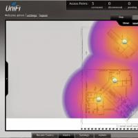 Seamless Wi-Fi Useful reviews about the work of capsman
 How to talk to Alice Screenshots Yandex with Alice
 Mts bonus program is closed
 Mobile communications and internet in the resorts of montenegro