Lowing voltage converter DC. Increased voltage converter DC DC. History - Linear Stabilizers
DC / DC transducers are very widely used for powering various electronic equipment. They are used in computing devices, communication devices, various control and automation schemes, etc.
Transformer power supplies
In traditional transformer blocks power supply voltage with a transformer is converted, most often drops to the desired value. Reduced voltage and smoothed by a condenser filter. If necessary, after the rectifier, a semiconductor stabilizer is set.
Transformer power supplies are usually equipped with linear stabilizers. These stabilizers in such stabilizers are at least two: it is a small cost and a slight number of parts in the strapping. But these advantages eaten a low efficiency, since a significant part of the input voltage is used to heat the adjusting transistor, which is completely unacceptable for powering portable electronic devices.
DC / DC converters
If the equipment is powered by electroplating elements or batteries, the voltage conversion to the desired level is possible only with DC / DC converters.
The idea is quite simple: constant pressure It is converted to a variable, as a rule, with a frequency of several dozen and even hundreds of kilohertz, rises (decrease), and then straightened and fed to the load. Such converters are often referred to as impulse.
As an example, you can bring the boost converter from 1.5V to 5V, just the output voltage of the computer USB. Such a small power converter is sold to Aliexpress.
Fig. 1. Converter 1.5V / 5V
Pulse converters are good because they have a high efficiency, in the range of 60..90%. Another advantage pulse converters A wide range of input voltages: the input voltage may be lower than the output or much higher. In general, DC / DC converters can be divided into several groups.
Classification of converters
Strong, in English terminology STEP-DOWN or BUCK
The output voltage of these converters, as a rule, is below the input: without special losses for heating the adjusting transistor, it is possible to obtain a voltage of only slightly volts at the input voltage of 12 ... 50V. The output current of such converters depends on the need of load, which in turn determines the circuitry of the converter.
Another English-speaking name of the chopper lowering converter. One of the options for the translation of this word is a breaker. In the technical literature, the downward converter is sometimes called "Chopper". So far just remember this term.
Strong, on English terminology STEP-UP or Boost
Output voltage of these converters above the input. For example, at the input voltage of 5V, the output can be obtained voltage up to 30V, and its smooth regulation and stabilization is possible. Frequently frequent converters are called boosters.
Universal Converters - Sepic
The output voltage of these converters is held at a specified level at the input voltage both above the input and lower. Recommended in cases where the input voltage may vary in significant limits. For example, in the car, the battery voltage may vary within 9 ... 14V, and it is required to obtain a stable voltage of 12V.
Inverting Converters - Inverting Converter
The main function of these converters is to obtain a reverse polarity voltage relative to the power supply. Very convenient in cases where two-polar nutrition is required, for example.
All mentioned converters can be stabilized or unstable, the output voltage can be galvanically connected with the input or having electroplating stress. It all depends on specific devicewhere the converter will be used.
To go to a further story about DC / DC converters, at least in general terms deal with the theory.
Lowing Converter Chopper - BUCK Type Converter
Its functional diagram is shown in the figure below. The arrows on the wires are shown the directions of currents.

Fig.2. Functional scheme of a chopper stabilizer
The UIN input voltage is fed to the input filter - CIN condenser. A VT transistor is used as a key element, it exercises high-frequency current switching. It can be either. In addition to these parts, the diagram contains a discharge diode VD and the output filter - LCOUT, from which the voltage enters the load of RN.
It is easy to see that the load is enabled sequentially with elements VT and L. Therefore, the scheme is consistent. How does the voltage drops?
Pulse modulation - PWM
The control circuit produces rectangular pulses with a constant frequency or a constant period, which is essentially the same. These impulses are shown in Figure 3.

Fig.3. Pulses of control
Here there are pulse time, the transistor is open, TP is a pause time, the transistor is closed. The TI / T ratio is called the filling coefficient of Duty Cycle, denotes the letter D and is expressed in %% or simply in numbers. For example, with D equal to 50%, it turns out that d \u003d 0.5.
Thus, D can vary from 0 to 1. With the value of d \u003d 1, the key transistor is in a state of full conductivity, and when D \u003d 0 is in a condition of the cutoff, simply speaking, closed. It is easy to guess that at d \u003d 50% the output voltage will be equal to half the input.
It is obvious that the regulation of the output voltage occurs due to the change in the width of the control pulse T and, in fact, by changing the coefficient D. This principle of regulation is called (PWM). Almost all pulse blocks Nutrition With the help of PWM, the output voltage is stabilized.
In the diagrams shown in Figures 2 and 6 PWM "hidden" in rectangles with the inscription "Control Scheme", which performs some additional functions. For example, it may be a smooth start of the output voltage, remote inclusion or protection of the converter from a short circuit.
In general, the converters received such a wide application that firms manufacturers electronic components We set out the release of PWM controllers for all occasions. The range is so great that simply to list them will need a whole book. Therefore, collect converters on discrete elements, or as often spoken on the "scattering", does not occur anyone.
Moreover, ready-made small power converters can be bought on Aliexpres or eBay for a minor price. At the same time, to install in an amateur design, it is enough to solder the wires to the input and output, and set the required output voltage.
But back to our Figure 3. In this case, the coefficient D determines how long it will be opened (phase 1) or closed (phase 2). For these two phases, you can submit a diagram with two figures. The figures do not show those elements that are not used in this phase.

Fig.4. Phase 1.
With an open transistor current from the power supply ( galvanic cell, battery, rectifier) \u200b\u200bpasses through inductive choke L, RN load, and charging COUT capacitor. At the same time, the current flows through the load, Cout condenser and choke L is accumulated energy. The IL current gradually increases, the effect of choke inductance affects. This phase is called pumping.
After the load voltage reaches the specified value (determined by the adjustment of the control device), the VT transistor closes and the device moves to the second phase - the discharge phase. The closed transistor in the figure is not shown at all, as if it is not. But this means only the fact that the transistor is closed.

Fig.5. Phase 2.
With a closed transistor VT, the replenishment of energy in the throttle does not occur, since the power supply is disabled. The inductance L strives to prevent the change in the value and direction of the current (self-induction) flowing through the winding of the throttle.
Therefore, the current cannot be stopped instantly and closes through the "diode load" chain. Because of this, the VD diode was called bit. As a rule, this is a high-speed Schottky diode. Upon expiration of the phase control period 2, the diagram switches to the phase 1, the process is repeated again. The maximum voltage at the output of the considered scheme may be equal to the input, and no more. To get the output voltage more than the input, the boiling converters are applied.
So far, you should remind itself about the value of inductance, which defines two modes of the chopper. With insufficient inductance, the converter will operate in the mode of discontinuous currents, which is completely unacceptable for power sources.
If the inductance is quite large, then the work occurs in the mode of inseparable currents, which allows the output filters to obtain a constant voltage with an acceptable level of ripples. In the mode of inseparable currents, there are also boost converters, which will be discussed below.
For a certain increase in the efficiency, the discharge diode VD is replaced with the MOSFET transistor, which at the right time opens the control circuit. Such converters are called synchronous. Their use is justified if the power of the converter is large enough.
Raising Step-Up or Boost Converters
The increasing converters are used mainly at low-voltage power, for example, from two or three batteries, and some design nodes require a voltage of 12 ... 15V with low current consumption. A fairly often boost converter briefly and clearly called the word "booster".

Fig.6. Functional diagram of an increase in converter
The UIN input voltage is fed to the CIN input filter and enters the connected L and the VT switching transistor. A diode VD is connected to the connection of the coil and drain of the transistor. To another diode output, the load of RN and the COUT shunt condenser is connected.
The VT transistor is controlled by a control circuit that produces a stable frequency control signal with an adjustable filling coefficient D, as well as it was described slightly higher when describing a chopper scheme (Fig. 3). VD diode at the right moments of time blocks the load from the key transistor.
When the key transistor is open, the output of the coil L connects with the negative pole of the UIN power supply. The growing current (influences the effect of inductance) from the power source proceeds through the coil and outdoor transistorEnergy accumulates in the coil.
At this time, the VD diode blocks the load and output capacitor from the key scheme, thereby preventing the discharge of the output capacitor through the outdoor transistor. The load at this point is powered by the energy accumulated in the COUT condenser. Naturally, the voltage on the output capacitor drops.
As soon as the output voltage becomes somewhat below the specified, (determined by the settings of the control circuit), the key transistor VT closes, and the energy stored in the throttle, through the VD diode recharges the COUT capacitor, which feeds the load. At the same time, the self inducidation of the coil L is folded with the input voltage and is transmitted to the load, therefore, the outlet voltage is obtained larger input voltage.
Upon reaching output voltage installed level Stabilization The control circuit opens the VT transistor, and the process is repeated from the energy accumulation phase.
Universal converters - Sepic (Single-Ended Primary-Inductor Converter or converter with asymmetrically loaded primary inductance).
Such converters are used mainly when the load has a slight power, and the input voltage varies relative to the output to a larger or smaller side.

Fig.7. SEPIC converter functional circuit
It is very similar to the diagram of an increase in the converter shown in Figure 6, but has additional elements: C1 condenser and a L2 coil. These are precisely these elements and ensure the operation of the converter in the voltage drop mode.
SEPIC converters are used in cases where the input voltage varies widely. As an example, you can cite 4V-35V to 1.23V-32V Boost Buck Voltage Step Up / Down Converter Regulator. It is under the title in chinese stores A converter is for sale, the diagram of which is shown in Figure 8 (to enlarge click on the drawing).

Fig.8. Schematic scheme SEPIC converter
Figure 9 shows the appearance of the board with the designation of the main elements.
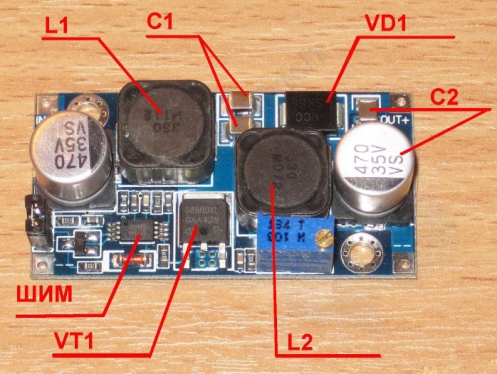
Fig.9. Appearance SEPIC converter
The figure shows the main parts in accordance with Figure 7. Attention should be paid to the presence of two coils L1 L2. This feature can determine that this is the sepic converter.
The input voltage of the board may be within 4 ... 35V. In this case, the output voltage can be adjusted within 1.23 ... 32V. Operating frequency converter 500kHz. In minor sizes 50 x 25 x 12mm board provides power up to 25 W. Maximum output current up to 3a.
But here you should make a remark. If the output voltage is set at 10V, the output current cannot be higher than 2,5A (25W). At the output voltage of 5V and the maximum current 3a, the power will be only 15W. Here the main thing is not to rearrange: either not exceed the maximum permissible power, or do not go beyond the permissible current.
There are no one for devices with battery powered by any kind of toys and gadgets feeding from a battery or batteries from a dozen in every home. Meanwhile, few people wondered over the number of diverse converters, which are used to obtain the necessary stresses or currents from standard batteries. These most converters are divided into several dozen different groups, each with their own characteristics, but at the moment we are talking about lowering and increasing voltage converters, which are most often called AC / DC and DC / DC converters. In most cases, specialized microcircuits are used to build such converters, allowing the converter of a specific topology with a minimal amount of strapping, the benefit of the chip in the market is now a great set.
Consider the features of these microcircuits can be infinitely long, especially taking into account the whole library of datasheets and appnetuses from producers, as well as an innumerable number of conditionally advertising reviews from representatives of competing firms, each of which tries to submit their product to the highest quality and versatile. This time we will use the discrete elements on which we will collect several converters that enhance DC / DC employees to power the small low-power device, for example, a LED, from 1 battery with 1.5 volt voltage. These voltage converters can be safely considered a weekend project and recommend for assembling to those who make their first steps to the amazing world of electronics.
This scheme presents a relaxation autogenerator, which is a block generator with a counter-inclusion of a transformer winding. The principle of operation of this converter is as follows: when turned on, the current flowing through one of the transformer windings and the emitter transition transistor - opens it, as a result of which it opens and larger current starts to flow through the second winding of the transformer and the outdoor transistor. As a result, in the winding connected to the transistor base, an emf is guided, the locking transistor and the current through it is broken. At this moment, the energy stored in the magnetic field of the transformer, as a result of the phenomenon of self-induction, is released and the current begins to flow through the LED, causing it to glow it. Then the process is repeated.

Components from which you can collect this simple voltage converter can be completely different. The scheme assembled without errors, with a huge share of the probability will work correctly. We tried to use even the MP37B transistor - the converter operates perfectly! The most difficult is the manufacture of a transformer - it must be coated with a dual wire on a ferrite rheel, while the number of turns does not play a special role and is in the range from 15 to 30. Less - it does not always work, more - it does not make sense. Ferrite - any, to take N87 from EPCOS does not make much sense, as well as looking for M6000NH domestic production. Currents in the circuit proceed with meager, so the ring size can be very small, the outer diameter of 10 mm will be more than enough. The resistor resistance is about 1 kiloma (there was no difference between resistors with a par 750 ohm and 1.5 com). The transistor is desirable to choose with minimal saturation voltage than it is less - the more discharged battery can be used. Experimentally checked: MP 37b, BC337, 2N3904, MPSH10. The LED is any existing, with the reservation, that the powerful multi-art will not be reduced in force.
The collected device is as follows:

The size of the board is 15 x 30 mm, and can be reduced to less than 1 square centimeter when using SMD components and a sufficiently small transformer. Without load this scheme does not work.


The second scheme is a typical step-up converter, made on two transistors. The plus of this scheme is that when it is manufactured, it is not necessary to wind the transformer, but it is enough to take the finished choke, but it contains more details than the previous one.
The principle of operation is reduced to the fact that the current through the choke is periodically interrupted by the VT2 transistor, and self-induction energy is sent through a diode into the C1 capacitor and is given to the load. Again, the scheme is operational with completely different components and rates of elements. The VT1 transistor can be BC556 or BC327, and VT2 BC546 or BC337, VD1 diode is any Schottky diode, for example, 1N5818. Capacitor C1 - any type, with a capacity from 1 to 33 μF, no longer makes sense, especially since it is possible to do without it. Resistors - with a capacity of 0.125 or 0.25 W (although it is possible to put powerful wire, watts to 10, but it is rather waste than the need for the following denominations: R1 - 750 Ohm, R2 - 220 com, R3 - 100 com. At the same time, all the ratings of resistors can be completely freely replaced with those in stock within 10-15% of those specified, this does not affect the performance of the correctly assembled scheme, but it affects the minimum voltage at which our converter can work.
 The most important detail - throttle L1, its nominal may also differ from 100 to 470 μH (experimentally tested the rates of up to 1 mG - the scheme works stable), and the current to which it must be calculated does not exceed 100 mA. LED - any, again, taking into account the fact that the output power of the circuit is very small. The correctly assembled device immediately starts to work and does not need to be configured.
The output voltage can be stabilized by setting the stabilion of the required nominal value parallel to the C1 condenser, however, it should be remembered that when the consumer is connected, the voltage may notice and become insufficient.ATTENTION! Without load, this scheme can produce tens of dozens or even hundreds of volts! In the case of use without a stabilizing element at the output, the C1 condenser will be charged to the maximum voltage, which in the case of a subsequent connection of the load can lead to its failure!
The converter is also made on a circuit board with a size of 30 x 15 mm, which allows you to attach it to the battery compartment of the size AA. The wiring of the printed circuit board is as follows:


Both simple schemes Increased converters can be made with their own hands andit is successfully used in hiking conditions, for example, in a lantern or lamp for the lighting of the tent, as well as in various electronic homemakes, for which the use of the minimum number of batteries is critical.
It would seem that you can also write about the rising module MT3608. After articles OT. kirich.?
But I have my little use, and I even didn't have enough brains to think about it: prompted the familiar. An article for those who in the Chinese multimeter village of Krona Battery.
First of all, I was attracted by a low price, and I somehow did not look at the rating of the seller ... On Ali, sometimes, very rarely, but there are normal sellers with a low rating. For a good start on the market, you need to make a maximum of effort and this seller, IMHO, it understands perfectly. 
I ordered for an amount of at least $ 2: 4 overlooked modules and - the order came after 16 days (Ukraine, Kharkov), and transistors were not 50, and 100!
Judging by the fact that they will be called by a positive diploma at the base, it is n-P-N, resistance base-collector and base-emitter 773. I noticed before the cases that additional buns are sent to the first buyer, this time was lucky to me! 
Packaged parcel is not without pupil, the return address is almost "kjuby": 
So, let's go back to the multimeter ... That's how it looks like me: 
hise batteries! All this lies on the table and almost not transportable. For its normal operation, it is necessary to voltage around 8-9V, the current "extremely small" (nothing to measure). I don't want to buy a crown, for that there are many batteries and to somehow relieve the design it was decided to put inside the boost module. 
LEDs on it are not - and that's good! It is a pity to disappear, it's tired of squeezing with black thermoclaim.
We connect the power supply (2 or more volt) to the board input rotating the variable resistor and so far a living multimeter control the voltage at the output of the board: 
When the voltage is changed at the input, the specified is kept at the output 
Install in 9-s-something volt.
Before the board, you can set the switch, the battery (s) can be placed inside the case, you can even handle it with charge charges for $ 0.2. 
But a couple of batteries on the wires do not hurt the outside, so more universally.
Included on the transvelon - fries - flooded: 
A more complete and qualified overview of this and other similar to the raising modules from kirich. You can read the link - - and it is better to read this article before the manipulations described in this, there are useful tips;)
You can also have other reviews of this module.
This is a DC-DC voltage converter from 5-13 V at the inlet, up to 12 on the output direct current 1.5 A. The converter receives a smaller voltage and gives a higher output to use where there is a voltage of a smaller required 12 volt. Often it is used to increase the voltage of the available batteries. This is essentially an integrated DC-DC converter. For example: there is a lithium-ion battery 3.7 V, and its voltage using this scheme can be changed to provide the necessary 12 V by 1.5 A.
The converter is easy to build on its own. The main component is the MC34063 chip, which consists of a source of reference voltage (temperature-compensated), comparator, generator with an active loop limit outline, valve (element "and"), trigger and powerful driver with a driver and requires only a few additional electronic components. In the strapping to be ready. This chip series was specifically designed to include them in various converters.

The advantages of the microcircuit MC34063A.
- Work from 3 to 40 in the entrance
- Low current in standby mode
- Current restriction
- Output current up to 1.5 a
- Output voltage adjustable
- Work in the frequency range up to 100 kHz
- Accuracy 2%

Description of radio elements
- R. - All resistors are 0.25 watts.
- T.- TIP31-NPN power transistor. All output current passes through it.
- L1- 100 microns Ferrite coils. If you have to do it yourself, you need to purchase toroidal ferrite rings with an outer diameter of 20 mm and an inner diameter of 10 mm, also 10 mm height and wire 1 - 1.5 mm thick 0.5 meters, and make 5 turns at equal distances. The dimensions of the ferrite ring are not too critical. The difference in several (1-3 mm) is acceptable.
- D.- Schottky diode must be used.
- Tr- multiple variable resistor, which is used here for accurate output voltage setting 12 V.
- C. - C1 and C3 polar capacitors, so pay attention to this when placing them on the printed circuit board.


List of parts for assembly
- Resistors: R1 \u003d 0.22 Ohm x1, R2 \u003d 180 Ohm x1, R3 \u003d 1.5 K x1, R4 \u003d 12K x1
- Controller: TR1 \u003d 1 com, multi-turn
- Transistor: T1 \u003d TIP31A or TIP31C
- Choke: L1 \u003d 100 μH on Ferrite Ring
- Diode: D1 - Schottky 1N5821 (21V - 3A), 1N5822 (28V - 3A) or MBR340 (40B - 3A)
- Condensers: C1 \u003d 100 μF / 25V, C2 \u003d 0.001 μF, C3 \u003d 2200 μF / 25V
- Microcircuit: MC34063.
- Printed circuit board 55 x 40 mm

Note that it is necessary to establish a small aluminum radiator on the T1 - TIP31 transistor, otherwise this transistor may be damaged due to increased heating, especially at high load currents. Datasheet and Picture Figure
 Cellular - what it is on the iPad and what's the difference
 Go to digital television: What to do and how to prepare?
 Social polls work on the Internet
 Savin recorded a video message to the Tyuments
 Menu of Soviet tables What was the name of Thursday in Soviet canteens
 How to make in the "Word" list alphabetically: useful tips
 How to see classmates who retired from friends?