How to make an antenna from a bicycle wheel. Homemade whip antenna for VHF transmitters. Do I need a calculation
It is not always advisable to buy a good antenna for a summer residence. Especially if she is visited from time to time. It is not so much a matter of costs, but of the fact that after a while it may not be in place. Therefore, many people prefer to make an antenna for a summer residence on their own. The costs are minimal, the quality is not bad. And the most important point - a TV antenna with your own hands can be made in half an hour or an hour and then, if necessary, can be easily repeated ...
Digital television in the DVB-T2 format is transmitted in the UHF range, and the digital signal is either present or not. If the signal is received, the picture is of good quality. Due to this. any decimeter antenna is suitable for receiving digital television. Many radio amateurs are familiar with the TV antenna, which is called "zigzag" or "eight". This DIY TV antenna is assembled in just a matter of minutes.
To reduce the amount of interference, a reflector is placed behind the antenna. The distance between the antenna and the reflector is selected experimentally - according to the "purity" of the picture  You can attach foil to the glass and get a good signal….
  Copper tube or wire is the best option, it bends well, it is easy to
It is very simple to make it, the material is any conductive metal: tube, rod, wire, strip, corner. She accepts, despite the simplicity, well. It looks like two squares (rhombuses) connected to each other. In the original, a reflector is located behind the square - for more confident signal reception. But it is more needed for analog signals. To receive digital television, it is quite possible to do without it or install it later if the reception is too weak.
Materials (edit)
Copper or aluminum wire with a diameter of 2-5 mm is ideal for this homemade TV antenna. In this case, everything can be done in literally an hour. You can also use a tube, corner, strip of copper or aluminum, but you will need some kind of device to bend the frames of the desired shape. The wire can be bent with a hammer, securing it in a vice.

You will also need a coaxial antenna cable of the required length, a plug that matches the connector on your TV, and some kind of mount for the antenna itself. The cable can be taken with a resistance of 75 ohms and 50 ohms (the second option is worse). If you make a TV antenna with your own hands for installation on the street, pay attention to the quality of the insulation.
The mount depends on where you are going to hang the DIY DTV antenna. On the upper floors, you can try to use it as a home and hang it on the curtains. Then you need large pins. At the dacha, or if you take a homemade TV antenna to the roof, you will need to attach it to a pole. Look for the right anchors for this case. For work, you will also need a soldering iron, sandpaper and / or a file, a file.
Do I need a calculation
There is no need to read the wavelength to receive a digital signal. It is simply desirable to make the antenna more broadband - in order to receive as many signals as possible. For this, some changes have been made to the original design (pictured above) (further in the text).
If you wish, you can make a calculation. To do this, you need to find out on what wavelength the signal is broadcast, divide by 4 and get the required side of the square. To obtain the required distance between the two parts of the antenna, make the outer sides of the rhombuses slightly longer and the inner ones shorter.

Drawing of an antenna "eight" for receiving digital TV
- The length of the "inner" side of the rectangle (B2) - 13 cm,
- "Outer" (B1) - 14 cm.
Due to the difference in lengths, a distance is formed between the squares (they should not be connected). The two extreme sections are made 1 cm longer - so that you can roll up the loop to which the coaxial antenna cable is soldered.
Frame making
If you count all the lengths, you get 112 cm. Cut off the wire or whatever material you have, take the pliers and a ruler, and begin to bend. The corners should be 90 ° or so. With the lengths of the sides, you can be a little mistaken - this is not fatal. It turns out like this:
- The first section is 13 cm + 1 cm per loop. The loop can be bent immediately.
- Two sections of 14 cm.
- Two 13 cm each, but with a turn in the opposite direction - this is the place of inflection to the second square.
- Again, two of 14 cm.
- The last one is 13 cm + 1 cm per loop.
The antenna frame itself is ready. If everything was done correctly, a distance of 1.5-2 cm was obtained between the two halves in the middle. There may be slight discrepancies. Next, we clean the hinges and the place of inflection to clean metal (process with emery with fine grain), tin. Connect two loops, squeeze with pliers to hold tight.

Preparing the cable
We take the antenna cable, carefully clean it. How to do this is shown in a step-by-step photo. You need to strip the cable from both sides. One edge will attach to the antenna. Here we clean it so that the wire sticks out by 2 cm.If it turns out more, the excess (later) can be cut off. Twist the screen (foil) and braid into a bundle. It turned out to be two conductors. One is the central mono-conductor of the cable, the second is twisted from a variety of braid wires. Both are needed and they need to be tinned.

We solder the plug to the second edge. A length of 1 cm or so is sufficient here. Also form two conductors, tin.
The plug in the places where we will carry out the soldering, wipe it with alcohol or solvent, clean it with emery (you can use a file). Put the plastic part of the plug on the cable, now you can start soldering. We solder a mono-core to the central outlet of the plug, and a multi-core twist to the side outlet. The last is to squeeze the grip around the insulation.

Then you can simply screw on the plastic tip, you can fill it with glue or non-conductive sealant (this is important). While the glue / sealant is not frozen, quickly assemble the plug (screw the plastic part), remove the excess composition. So the plug will be almost permanent.
DIY DVB-T2 TV antenna: assembly
Now it remains to connect the cable and frame. Since we were not tied to a specific channel, we will solder the cable to the midpoint. This will increase the antenna bandwidth - more channels will be received. Therefore, we solder the second cut end of the cable to the two sides in the middle (those that were stripped and tinned). Another difference from the "original version" is that the cable does not need to be traced around the frame and soldered at the bottom. This will also expand the reception range.
The assembled antenna can be checked. If the reception is normal, you can finish the assembly - fill the soldering points with sealant. If the reception is poor, first try to find a place where you fish best. If there are no positive changes, you can try to replace the cable. For simplicity of the experiment, you can use regular telephone noodles. It costs a penny. Solder the plug and frame to it. Try with her. If it "catches" better, it's a bad cable. In principle, you can work on "noodles", but not for long - it will quickly become unusable. Better, of course, to put a normal antenna cable.

To protect the junction of the cable and the antenna frame from atmospheric influences, the soldering points can be wrapped with ordinary electrical tape. But this is not a reliable way. If you don't forget, you can put on some heat shrink tubes before soldering to insulate with them. But the most reliable way is to fill everything with glue or sealant (they should not conduct current). As a "body" you can use lids for 5-6 liter water cylinders, ordinary plastic roofs for cans, etc. We make grooves in the right places - so that the frame "lays down" in them, do not forget about the cable outlet. Fill with a sealing compound, wait until it grabs. That's it, a do-it-yourself TV antenna for receiving digital television is ready.
Homemade antenna double and triple square
This is a narrowband antenna, which is used if you need to receive a weak signal. It can even help if a weaker signal is “clogged” with a stronger one. The only drawback is that you need an accurate orientation to the source. The same design can be made to receive digital television.
 You can also make five frames - for more confident reception
  It is undesirable to paint or varnish - the reception deteriorates. This is only possible in the immediate vicinity of the transmitter.
The advantages of this design are that the reception will be reliable even at a considerable distance from the repeater. Only it will be necessary to specifically find out the broadcasting frequency, maintain the dimensions of the frames and the matching device.
Construction and materials
They make it from tubes or wire:
- 1-5 TV channel MV range - tubes (copper, brass, aluminum) with a diameter of 10-20 mm;
- 6-12 TV channel MV range - tubes (copper, brass, aluminum) 8-15 mm;
- UHF range - copper or brass wire with a diameter of 3-6 mm.
The double square antenna consists of two frames connected by two arrows - an upper and a lower one. The smaller frame is the vibrator, the larger one is the reflector. An antenna consisting of three frames gives a higher gain. The third, smallest, square is called the director.

The upper boom connects the middle of the frames, can be made of metal. The lower one is made of insulating material (textolite, gettinax, wooden plank). The frames should be installed so that their centers (points of intersection of the diagonals) are on the same straight line. And this line should be directed to the transmitter.
The active frame - vibrator - has an open circuit. Its ends are screwed to a textolite plate 30 * 60 mm in size. If the frames are made of a tube, the edges are flattened, holes are made in them and the lower boom is attached through them.
The mast for this antenna must be wooden. In any case, the upper part. Moreover, the wooden part should start at a distance of at least 1.5 meters from the level of the antenna frames.
Dimensions (edit)
All dimensions for making this TV antenna with your own hands are shown in the tables. The first table is for the meter range, the second for the decimeter range.

In three-frame antennas, the distance between the ends of the vibrator (middle) frame is made larger - 50 mm. Other dimensions are given in the tables.

Connecting an active frame (vibrator) through a short-circuited loop
Since the frame is a symmetrical device, and it must be connected to an unbalanced coaxial antenna cable, a matching device is required. In this case, a balancing short-circuited loop is usually used. It is made from pieces of antenna cable. The right segment is called the “loop”, the left one is called the “feeder”. A cable is attached to the junction of the feeder and the loop, which goes to the TV. The length of the segments is selected based on the wavelength of the received signal (see the table).

A short piece of wire (loop) is cut from one end by removing the aluminum screen and twisting the braid into a tight bundle. Its center conductor can be cut to insulate as it does not matter. The feeder is also cut. Here, too, the aluminum screen is removed and the braid is twisted into a bundle, but the central conductor remains.
Further assembly takes place like this:
- The loop sheath and the center conductor of the feeder are soldered to the left end of the active frame (vibrator).
- The feeder sheath is soldered to the right end of the vibrator.
- The lower end of the loop (braid) is connected to the braid of the feeder using a rigid metal jumper (you can use a wire, just make sure there is good contact with the braid). In addition to the electrical connection, it also sets the distance between the sections of the matching device. Instead of a metal jumper, you can twist the braid of the lower part of the loop into a bundle (remove the insulation in this area, remove the screen, roll up into a bundle). To ensure good contact, the bundles must be soldered together with low-melting solder.
- The pieces of cable must be parallel. The distance between them is about 50 mm (some deviations are possible). To fix the distance, clamps made of dielectric material are used. You can also attach the matching device to the textolite plate, for example.
- The cable leading to the TV is soldered to the bottom of the feeder. The braid connects to the braid, the center conductor to the center conductor. To reduce the number of connections, the feeder and cable to the TV can be made one. Only in the place where the feeder should end should the insulation be removed so that a jumper can be installed.
This matching device allows you to get rid of interference, blurred contour, second blurry image. It is especially useful at a great distance from the transmitter, when the signal is clogged with interference.
Another variant of the triple square
In order not to connect a short-circuited loop, the triple square antenna vibrator is made elongated. In this case, you can connect the cable directly to the frame as shown in the figure. Only the height at which the antenna wire is soldered is determined in each case individually. After assembling the antenna, a "test" is carried out. Connect the cable to the TV, move the center conductor and braid up / down for a better picture. In the position where the picture will be the clearest, the taps of the antenna cable are soldered, the soldering points are insulated. The position can be any - from the lower jumper to the place of transition to the frame.

Sometimes one antenna does not give the desired effect. The signal is obtained by a weak image - black and white. In this case, the standard solution is to install a TV signal amplifier.
The simplest antenna for giving is from metal cans
For the manufacture of this television antenna, in addition to the cable, you will need only two aluminum or tin cans and a piece of wooden plank or plastic pipe. Banks must be made of metal. You can take beer aluminum, you can - tin. The main condition is that the walls are even (not ribbed).

Banks are washed and dried. The end of the coaxial wire is cut - by twisting the braid cores and clearing the central core from the insulation, two conductors are obtained. They are attached to banks. If you know how, you can solder. No - take two small self-tapping screws with flat caps (you can use "fleas" for drywall), twist a loop at the ends of the conductors, thread a self-tapping screw with a washer installed on it, screw it to the bank. Just before that, you need to clean the metal of the can - by removing the plaque with sandpaper with a fine grain.

Banks are fixed on the bar. The distance between them is selected individually - according to the best picture. Do not hope for a miracle - there will be one or two channels in normal quality, or maybe not ... Depends on the position of the repeater, "cleanliness" of the corridor, how correctly the antenna is oriented ... But as a way out in an emergency, this is a great option.
Simple antenna for Wi-Fi from a metal can
An antenna for receiving a Wi-Fi signal can also be made from improvised means - from a tin can. This DIY TV antenna can be assembled in half an hour. This is if you do everything slowly. The can should be made of metal, with smooth walls. Tall and narrow cans are great. If you are installing a homemade antenna on the street, find a jar with a plastic lid (as in the photo). The cable is taken from the antenna, coaxial, with a resistance of 75 ohms.

In addition to the can and cable, you will also need:
- RF connector RF-N;
- a piece of copper or brass wire with a diameter of 2 mm and a length of 40 mm;
- cable with a socket suitable for the Wi-Fi card or adapter.
Wi-Fi transmitters operate at 2.4 GHz with a wavelength of 124 mm. So, it is advisable for a bank to choose such that its height is at least 3/4 of the wavelength. For this case, it is better that it be more than 93 mm. The can diameter should be as close to half the wavelength as possible - 62 mm for a given channel. There may be some deviations, but the closer to the ideal, the better.
Dimensions and assembly
When assembling, a hole is made in the jar. It must be positioned strictly at the desired point. Then the signal will be amplified several times. It depends on the diameter of the selected can. All parameters are shown in the table. You measure exactly the diameter of your can, find the right line, have all the right dimensions.

| D - diameter | Lower attenuation limit | Attenuation upper limit | Lg | 1/4 Lg | 3/4 Lg |
|---|---|---|---|---|---|
| 73 mm | 2407.236 | 3144.522 | 752.281 | 188.070 | 564.211 |
| 74 mm | 2374.706 | 3102.028 | 534.688 | 133.672 | 401.016 |
| 75 mm | 2343.043 | 3060.668 | 440.231 | 110.057 | 330.173 |
| 76 mm | 2312.214 | 3020.396 | 384.708 | 96.177 | 288.531 |
| 77 mm | 2282.185 | 2981.170 | 347.276 | 86.819 | 260.457 |
| 78 mm | 2252.926 | 2942.950 | 319.958 | 79.989 | 239.968 |
| 79 mm | 2224.408 | 2905.697 | 298.955 | 74.738 | 224.216 |
| 80 mm | 2196.603 | 2869.376 | 282.204 | 070.551 | 211.653 |
| 81 mm | 2169.485 | 2833.952 | 268.471 | 67.117 | 201.353 |
| 82 mm | 2143.027 | 2799.391 | 256.972 | 64.243 | 192.729 |
| 83 mm | 2117.208 | 2765.664 | 247.178 | 61.794 | 185.383 |
| 84 mm | 2092.003 | 2732.739 | 238.719 | 59.679 | 179.039 |
| 85 mm | 2067.391 | 2700.589 | 231.329 | 57.832 | 173.497 |
| 86 mm | 2043.352 | 2669.187 | 224.810 | 56.202 | 168.607 |
| 87 mm | 2019.865 | 2638.507 | 219.010 | 54.752 | 164.258 |
| 88 mm | 1996.912 | 2608.524 | 213.813 | 53.453 | 160.360 |
| 89 mm | 1974.475 | 2579.214 | 209.126 | 52.281 | 156.845 |
| 90 mm | 1952.536 | 2550.556 | 204.876 | 51.219 | 153.657 |
| 91 mm | 1931.080 | 2522.528 | 201.002 | 50.250 | 150.751 |
| 92 mm | 1910.090 | 2495.110 | 197.456 | 49.364 | 148.092 |
| 93 mm | 1889.551 | 2468.280 | 194.196 | 48.549 | 145.647 |
| 94 mm | 1869.449 | 2442.022 | 191.188 | 47.797 | 143.391 |
| 95 mm | 1849.771 | 2416.317 | 188.405 | 47.101 | 141.304 |
| 96 mm | 1830.502 | 2391.147 | 185.821 | 46.455 | 139.365 |
| 97 mm | 1811.631 | 2366.496 | 183.415 | 45.853 | 137.561 |
| 98 mm | 1793.145 | 2342.348 | 181.169 | 45.292 | 135.877 |
| 99 mm | 1775.033 | 2318.688 | 179.068 | 44.767 | 134.301 |
The procedure is as follows:

You can do without an RF connector, but everything is much simpler with it - it is easier to set the emitter vertically upward, connect the cable going to the router (router) or Wi-Fi card.
To make a TV antenna, you will need:
- aluminum or copper wire;
- antenna connector;
- wood;
- 2 bicycle rims;
- board;
- plastic sewer pipe;
- plastic pipes;
- carpentry or locksmith tools.
The wire should be solid, but thick enough. A TV cable is ideal, but you may not always have it on hand.
If the TV center is close
In exceptional cases, when the telecentre is located close to the receiving point, the signal can be received simply on a piece of wire. Take 1.5 m of thick aluminum wire, strip about 1 cm from one end, use to adjust the thickness to the center socket of the TV antenna connector. Plug the wire into the connector. Turning the wire vertically or horizontally, bending it at different points and adjusting the length empirically, tune the antenna to the television station. This method is suitable when the distance to the telecentre is less than 1 km.Universal antenna
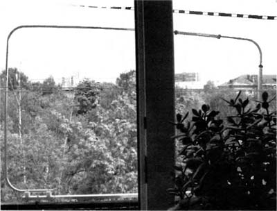
In other cases, you will need to make a special antenna. One of the main requirements for a TV antenna is its broadband. It is possible to make a broadband dipole antenna from available tools. Such an antenna will consist of two vibrators. For it to be broadband, their area must be large. Take 2 rims from bicycle wheels with spokes and fix them on an insulating beam so that the distance between the edges of the rims is about 50 cm.As such a beam, you can use a piece of sewer plastic pipe (preferably made of light plastic, it has better insulating properties), wooden a board (in this case, take care of insulation, since a wet tree can conduct current), any other insulating material of sufficient size and strength.Use screws or rivets to tap off each of the rims. Connect the taps to the TV using a two-wire line. This method is suitable for TVs with a high impedance input (200 ohms). But most often TVs are equipped with a 75-50 ohm coaxial input; to connect your antenna to such a TV, you will need a matching transformer. It is made from pieces of coaxial cable. It is also connected to the TV using a coaxial cable. Not only wheels from an old bicycle are suitable as dipole vibrators. You can use, for example, sports aluminum hoops and any other objects of a suitable shape and size. Such an antenna has directivity, so it must be pointed at the TV center.
Convenient high-frequency (HF) connectors, splitters and adapters are no surprise today. Moreover, it is strange that they appeared for mass use by radio amateurs relatively recently, although they have been used in professional activities for decades, especially in radio measurements. Such HF accessories were previously attached to radio measuring devices as part of the delivery kits and spare parts, which was caused by the "variety" of input and output HF connectors, the geometry of coaxial cables and, to some extent, concern for ease of use and experiments. With their standardization, the situation has improved, but problems remain - in the West, inch dimensions of threads and diameters are used, and in our country, metric ones. Therefore, until now, RF accessories do not always "dock", causing significant inconveniences, for example, when using externally identical CP and BNC connectors. But this did not last long, because both suppliers and consumers, including radio amateurs, almost without exception switched to "external" standards for RF accessories and cable products.
Something similar, but for other tasks, takes place in a wide variety of technical areas, for example, in plumbing. There are also tubular (hose) connectors for different diameters and threads, adapters from "thread A" to "thread B", couplings, elbows, plugs, splitters, filters, fittings.

Many citizens are faced with this by installing meters for the consumption of water, gas, modern plumbing, boiler and gas equipment, changing outdated mixers, valves, etc.
Needless to say that the use of standard accessories is more convenient, much more technologically advanced than traditional soldering or metal welding, although not always cheaper - bayonet or threaded connections, plastic welding allow you to quickly and reliably perform installation by aggregating almost any "scheme" dictated by the functional purpose.
It should be noted that plumbing accessories for metal and plastic pipelines are different in materials and the principle of joining - threading and welding of plastics, respectively. Therefore, before purchasing them, the issue should be studied deeper in order to avoid unnecessary material costs.
The properties of reliability and manufacturability attract attention when building HF / VHF antennas and feeder devices, where accessories of both types can be successfully used. Wherein
it is necessary to keep in the field of attention the main issue - the conductive material of the emitter.
Suppose you want to mount a magnetic loop antenna. Radio amateurs know that the main difficulty in this case lies in the selection of a rigid antenna ring support of a relatively large diameter, which are sports hoops (duralumin, polyethylene) and even a bicycle wheel rim. However, with such solutions, it is not possible to vary the diameter of the structure, because it is initially set. This does not allow the desired antenna size to be fulfilled in most cases, since the designer is deprived of such an opportunity by “initial conditions”. Fan struts made of wood are also used, for example, according to the type of a circular zigzag antenna, but they occupy a certain area, "loading" the space, and are unstable in geometry and parameters.
It is much more convenient to use plumbing connectors and other accessories as an "antenna kit". A tubular plumbing connector (TCC) is a piece of flexible pipe, solid or corrugated cylindrical, made of metal (copper, stainless steel) or plastic. Plastic TCCs are often reinforced with an outer mesh braid made of wire with an anti-corrosion coating. The TCC is equipped with two lugs "socket" - "pin" with an internal and external thread 1/2 "(about 12mm), respectively. By swirling a few TCCs, we get the desired size; in this case, the structure can be given the shape of a broken line, circle or polygon.
It is preferable to use, of course, TCC made of copper tubes, because the magnetic loop antenna is characterized by large currents. The shortened design may contain "inserts" of plastic TSS, if it is planned to use ladders, spiral or loop-type extensions in the body of the emitter, and a tuning capacitor. In such a scheme, plastic TCCs are used as frames for inductors, spirals or holders of loop modules, as well as dielectric gaps. The meaning of our constructions is to ensure the rigidity and manufacturability of the assembly of antenna structures in the process of experiments, research and, after achieving success, to fix the result.
The figure shows an ART 073 Trapped balcony antenna 10-15-20-40 m manufactured by ECO Antenne, Italy, in position.
Without going into details of its assignment to a specific type of shortened antennas (curved dipole or 0.25L pin, frame with ladders and telescopic trimming section), we see that it is easily repeated from the elements of our "antenna designer" as a possible type of geometry. At the same time, the cost of the antenna is reduced by an order of magnitude, and the efficiency of variation in dimensions is acquired over a wider range.
The following figure shows the balcony vertical of the VE3IVM-L VHF antenna in the working position, just as easily implemented using plumbing accessories, including tilt counterweights.

A design feature is the need for a basic dielectric splitter and external connection of the grounded antenna parts. Assembly and installation of Yagi antennas and other types of antennas seems to be no less convenient. Of course, there may be cases when the necessary fragments of the selected geometry are not included in the "constructor", for example, elements of fastening, fixation, isolation, but this is a common design practice, solved by a radio amateur in real conditions. These elements can be found in the range of accessories for wiring household electrical networks (plastic brackets, clamps, clamps, etc.).
It is pertinent to remind that the TCC connections must be made without gaskets, which should be removed from the union nuts and removed from the body of the threaded ends. Particular attention should be paid to interfacing the TCC with selected coaxial connectors (PL, SO, BNC). With careful execution of threaded connections using wrenches, the electrical parameters of the finished antenna structures do not differ in any way from their soldered (welded) counterparts.
Be creative, colleagues! 73!
The advent of personal computers led to the displacement of mainframes such as the EU. In our country, computing centers, having acquired personal computers, immediately dismantled and threw large computers simply into a landfill.
Many of the details that make up the discarded computers have been used by our savvy people. This is how a simple antenna appeared, made on the basis of an aluminum disk of the magnetic memory of the ES "Ryad" computer, which was at one time widespread in our vast country.
And now, 10 years after the "glorious" restructuring in our country, the antenna can be purchased on the market at an affordable price. Due to its simplicity of design, combined with good characteristics, the antenna became widespread and truly became a popular design.
Antenna design
This antenna is a disk with an outer diameter of 356 mm, an inner diameter of 170 mm and a thickness of 1 mm, in which a cut was made 10 mm wide (Fig. 1.e).
In place of the cut, a printed wiring board made of fiberglass with a thickness of 1 mm is installed (Fig. 1.6). This board has two holes for fixing the antenna with M3 screws.

Rice. 1. The design of a television antenna made of an aluminum disk of a computer magnetic memory (a) and a mounting plate attached to it (6).
The leads of the matching transformer and the drop cable are soldered to the printed circuit board attached to the antenna. An analysis of the quality of work showed that its work is largely determined by the presence of a matching transformer T1 (Fig. 2).
For a transformer, it is best to use a ring core with an outer diameter of 6 ... 10 mm, an inner diameter of 3 ... 7 mm and a thickness of 2 ... 3 mm.

Rice. 2. Diagram of the matching transformer of a television antenna made of an aluminum disk.
The transformer windings are wound with a single-core insulated wire with a core diameter of 0.2 ... 0.25 mm and have the same number of turns, from 2 to 3 turns. The length of the bobbins is approx. 20 mm.
In the presence of such a transformer, reception is possible in the meter and decimeter ranges at a distance of 25 ... 30 km from the television center. When the distance from the TV center is up to 50 km, the antenna with a transformer works satisfactorily only on decimeter channels.
At a distance of more than 50 km from the transmitting TV tower, the reception quality is poor. Without a matching transformer, the range of reception of TV programs on the antenna is halved. In this case, ghosting of the image appears and its clarity is lost. The reason lies in the mismatch between the antenna and the drop cable, the antenna has a balanced output, and the cable is unbalanced.
Two-disc option
Practice shows that it is possible to significantly improve the quality of reception on this antenna without a matching transformer. To do this, you need to assemble the antenna from two discs and connect the drop cable directly to the antenna leads (Fig. 3).
Structurally, such an antenna is made of two disks with cuts 10 mm wide, which are connected by two mounting plates made of double-sided foil-clad fiberglass with a size of 30x90 mm.
The connection can also be made with plates of one-sided foil-clad fiberglass, brass or copper with a thickness of 0.5 ... 1 mm. To connect the disks, 8 screws M3 or M4 are used.

Rice. 3. The design of the TV antenna from two aluminum disks of the computer's magnetic memory without a matching transformer.
The central core of the cable is soldered to point 1, and the braid - to point 2. The quality of TV signals reception on an antenna with two discs is higher than with one disc, which is noticeable especially at a great distance from the television center.
Literature: V.M. Pestrikov - Encyclopedia of radio amateurs.
On this page I posted a detailed photo of instructions for making a whip antenna for VHF-band transmitters, without understanding the very essence of the transmission of radio signals over the air. However, the article provides a calculation of the length of a quarter-wave whip antenna.
A quarter-wave VHF whip antenna (in the world of burglar alarms, just a “pin”) costs 200-300 rubles, retail. Branded antennas from C.NORD are called CN AGV and are sold in various standard sizes (the length of the pin adjusts to the frequency of the radio transmitter). Since such antennas are designed for radio transmitters of a fairly wide frequency range (146-174 MHz), then it is necessary to initially select the antenna of the required size or adjust (bite off the excess, but not increase, in this case, change to another antenna). Sometimes it is necessary to "bite off" excess from the whip antenna when switching an object from one PSC to another, because the transmitter frequency changes and the signals from a pin of the wrong length do not go well.
Now we will essentially make a copy of the CN AGV antenna, but we will make it for a specific frequency.
It all begins with the preparation of the necessary material, tools and with calculating the length of the pin, for a frequency of 163 325 kHz (I chose the frequency as an example, I do not know what kind of CHOP works on it).
For a homemade whip antenna, we need a tool: a soldering iron, a hair dryer (you can use a gas lighter, nippers, sandpaper; material: galvanized wire 2-4 mm in diameter, solder, soldering acid, pl-259 connector, heat shrink tube.
Let's go back to the calculations. He described in detail on his notebook how the length of the quarter-wave whip antenna was calculated. You should also know that the length of the pin antenna is measured from the end of the washer of the pl-259 connector.
As a result, after all the calculations, we understand that the length of the pin, taking into account the soldering of the pl-259 connector, should be 49.9 cm. For the pin, I use ordinary galvanized wire with a thickness of 2-4 mm. It is tough enough to serve as a whip antenna.


Bend a piece of wire so that it becomes even. The quality of the antenna depends on this, so it will be even better if you can find a suitable thickness for a harder metal pin / wire / spoke.
Let's try on how our wire will fit into the connector. If it does not fit, as in our case, then we grind / sharpen the end of the wire using "sandpaper", but exactly as much as the end should go into the connector.

Trying on how the pin will "fit" into the plug


A screwdriver caught my eye, so I managed to sharpen the end of the wire quickly:
After the end of the wire began to freely enter the pl-259 connector, stop sharpening. It will be even better if it fits snugly inside the center hole of the connector.
The part of the wire that goes into the central plug of the connector must be treated with soldering acid and soldered with tin.


Put the VHF plug on the soldered end of the wire and mark for yourself that part of the wire that will touch the connector washer. Insulate this part from the washer as best as possible using heat shrinkage as shown in the figure and in the photo.

Insulate the entire pin with another heat-shrinkable tube, because the antenna should essentially be insulated.

Isolation of "dangerous" areas. In these places, the central core can be short-circuited with a common wire.


The plug can now be soldered. After soldering, be sure to "ring" with a multimeter to see if there is a short circuit between the central core and the nut of the pl-259 plug.


Now the antenna is ready, you can insert it into the radio transmitter. Be sure the signals from such an antenna will "reach" the repeater / base receiver.
 How to update iPad: instructions
 How Do Not Disturb mode works on iPhone
 Nokia 3310 when it came out. How they find us
 History of computer graphics in Russia 1 history of development of computer graphics
 Complete order: How to organize icons on a smartphone Complete order: How to organize icons on a smartphone
 Xiaomi Huami Amazfit Bip is the best smartwatch without any but even if
 What is Jailbreak and what is it for?