How to create a layer in AutoCAD? Layer properties manager. We use layers in AutoCAD Why do we need layers in AutoCAD
To be able to work in layers is necessary when performing any projects and any drawings.
A layer is a set of primitives united according to some criteria. Three properties that affect the display of an object on the screen are color, weight, and linetype. A combination of these three properties can be stored in autocad file memory as a separate layer. To create, delete and manage layers, you need to go to their property manager.
In the manager window, we see a list of layers that are in the drawing file and their properties. By the way, layers have much more properties than color, weight and line type.

Let's go through the main parameters of the layers, in addition to the previously announced color, weight and line type, there are also:
The first parameter is the layer status. The status can be current or minor. All new lines and texts you create will be on the current layer.
The second parameter is the name, or title, of each layer.
There is also a "Print" property. If this parameter is disabled, then all primitives drawn in this layer will not be printed.
The file always has a layer “0”. This layer cannot be deleted. It is understood that some sketches or sketches will be performed in this layer.
The “Defpoints” layer is intended for auxiliary constructions. Initially, it is absent in the drawing, but if we create it, then its characteristic feature will be that it cannot be made printed.
Other related lessons
In this video and tutorial, we'll show you how to work with properties in AutoCAD, as well as how the properties panel and copying work. The lesson will answer such questions: - What are Properties in AutoCAD? - How to enable the properties panel in AutoCAD? – What are quick properties and how to disable them? – How to copy properties in AutoCAD […]

In this lesson, we show what system requirements your computer or laptop must meet in order to work comfortably in AutoCAD. Video version of the lesson: Master AutoCAD in 40 minutes after completing the basic course from Maxim Fartusov. Text version of the lesson: Perhaps one of the most popular questions, along with how to download the AutoCAD program, is the question related to the system requirements of the AutoCAD program. […]
In this lesson, you will learn about what layers are in AutoCAD, why they are, how to create them and work using layers. Creating both simple and complex drawings consists in placing on it the required number of AutoCAD primitives (segment, polyline, spline, circle, arc, ...), hatching, gradient fill, text, dimensions, groups of primitives, blocks, etc..
There is one unique feature that unites all these objects − properties, which can be changed and reconfigured: select any color for the layer, set the line thickness for the layer, select the line type for the layer, add an explanation for the layer, etc.
Layers in AutoCAD: purpose and application
Layer Properties Manager
The CAD program AutoCAD has an indispensable tool - layer(Layer), with which it turns out to link together primitives and objects with the same properties in the drawings. For the convenience of work and increase the speed of editing the drawing, it is recommended to place objects of different types on different layers in AutoCAD. We can conditionally say that layers are tracing papers on which certain elements of the drawing are created.
And if you put these tracing papers one on top of the other, we get a complex drawing. For objects lying on the same layer, you can also set global properties ( ByLayer- by layer) and locally for any selected layers. By default, every drawing has a layer in AutoCAD called «0», which cannot be deleted, but the ability to edit properties is available. All other layers are created by you. Creating, editing and other manipulations with layers takes place in the window Layer Properties Manager, to call which we go to Format - Layer...

or click on the main panel on the tab Layers button. 
What are the properties of a layer in AutoCAD
Only one layer can be active (current) at a time, and all graphic objects are drawn on this layer. It is possible to make changes to the layer properties at any time and this feature is available regardless of which current layer is installed.
Layer properties in the window Layer Properties Manager:
| Name | The name of the layer is set, and the layer is selected to change its parameters (color, line type). Set as current when double-clicking with the left mouse pointer. |
| On | Controls the display of graphical primitives on this layer, can be turned on and off. All drawing elements on the disabled layer will not be displayed on the screen and cannot be printed, and editing will not be available. |
| To freeze | Allows you to freeze/unfreeze the layer for the entire drawing. All drawing elements on the frozen layer will not be displayed on the screen and will not be able to print, and will not be editable. |
| Block | Allows you to lock/unlock a layer for the entire drawing. |
| Color | Allows you to change the layer color for the entire drawing. If you change the color of a layer, then the color of all graphic objects that belong to this layer will change. |
| line type | Allows you to change the layer linetype for the entire drawing. Changing the linetype of a layer changes the linetype of all graphics objects that belong to that layer. |
| Line weight | Allows you to change the layer lineweight for the entire drawing. When you change the line weight of a layer, the line weight of all graphics objects that belong to that layer changes. |
| Transparency | Allows you to change the transparency of a layer in the entire drawing. |
| Print style | Allows you to change the layer plot style for the entire drawing. |
| Seal | Ability to enable/disable printing of the selected layer for the entire drawing. All graphics on this layer will be displayed on the screen, but will not be printed. |
| Frozen on new ve | Allows you to freeze the layer only in new viewports. |
| Explanation | Allows you to add/change the layer description for the entire drawing. |
Create a new layer in AutoCAD and edit an existing one
We click on the button Create layer which is in the window Layer Properties Manager.
By default, a new layer is created named Layer1 (Layer2, …, LayerN) and the ability to change the name of this layer immediately becomes available. It's not possible to create a layer name that is longer than 256 characters, but that's OK, as long names are awkward to work with. To change the name of a layer, double-click on it with the mouse, with a small interval between clicks (if you click 2 times in a row, you will make the layer current). By default, a new layer created in AutoCAD will have all the properties of the current layer (layer color, line type and weight, visibility, ...). To change any of the layer properties, click on the parameter we need in the list and set (select, specify) the required new value.
Set or change the color of a layer
To change the color of a layer:
- open Layer Properties Manager Color;

- in the window that appears, select the desired color from the color palette;

It is also possible to select any color on the tab All palette And Albums of flowers.
- click on the button OK to close the window and applying the selected color to the layer.
Set or change line type
To change the line type of a layer:
- open Layer Properties Manager and click in the line of the desired layer opposite the parameter line type;

- in the window that appears, select the type of line we need;

- click on the button OK to close the window Line type selection and apply the selected linetype for the layer in AutoCAD.
Set or change lineweight
To change the weight (thickness) of a layer line:
- open a window Layer Properties Manager and click in the line of the desired layer opposite the parameter Line weight;

- set (select) the line weight (thickness) in the window that appears Line weight;

- by pressing a button OK the window closes and the changes take effect.
After reading this article, you not only learned what layers are in AutoCAD, but also gained basic skills in working with them. Now you can not only create new (your own) layers, but also rename them, edit (set) the weight and choose the type of lines, etc.
Layers in AutoCAD is a lesson that will help you work faster and be one level above your fellow novice.
Novice users often wonder how to create a layer in AutoCAD?! This is not surprising, for each type of line in autocad you need to create a layer, this program has such a feature. Working with layers in AutoCAD causes a lot of errors when drawing up and printing a drawing. In this lesson, we will take a closer look at how to create a new layer in AutoCAD and how to edit the system layer.
How to create a layer in AutoCAD
Layers in AutoCAD are very important, so in the top panel of the main tab, in the most prominent place, there is a whole section related to their creation and management.
Conventionally, the "Layers" section can be divided into 3 components: 1 - Layer properties, including the settings of the current layer and the creation of new ones, 2 - Selecting the current layer, 3 - Controlling the current layer.
Let's create a new layer. To do this, click "Layer Properties". A window opens, now it contains only the system layer with the name 0, it cannot be renamed, but each new layer can be called by any name. A green checkmark means that this layer is currently active, you can switch to another layer by double-clicking the left mouse button.

Click the "Create Layer" button. When you hover over this button, a hint of "hot" keys pops up, so you can create it either by clicking the button with the mouse or by pressing Alt + D. The list of layers is updated, the new layer is initially named layer 1.

Rename if you wish. The ability to turn it on and off allows you to hide objects and prevent drawing on the selected layer until it is turned on again. Freezing allows you to hide layers to make the drawing easier to read, as well as to speed up your work. Layer locking does not hide drawing elements and allows you to create new objects when the current layer is selected, but it prohibits editing (deleting, trimming and extending lines, resizing, etc.)
Separately, it is worth highlighting the ability to set the color of the lines for each layer. This is very convenient and allows you to visually divide the drawing into components. To change the color, click on its name.

Select, confirm and the color is changed.
The next important layer step is the line type and weight. In the system layer, a thin line with a weight (thickness) by default. Often it is necessary to create basic lines, thin, axial, dashed, dotted and others. The number of line types in the drawing must match the number of layers created. Let's start with line types.

Click on the name of the line type, in the window that opens, select "Download".

For convenience, the program shows the image and the name of the line. Select the desired line, confirm, a new line with the name of the selected line type will appear in the "Select line type" window, select it, click "OK".
The weight of the line is assigned according to the standards of design documentation and must correspond to its type.

The layer transparency value is entered manually, it can be set from 0 to 90. The print style is not editable, this is an information field. The "Print" button, with the image of a printer, allows you to disable printing of the selected layer. Freezing on new viewports, respectively, is only responsible for additional viewports. In the "Explanations" field, if necessary, a comment is written.
We looked at creating and editing a layer. Before printing a drawing, you need to make sure that all the necessary layers are enabled for printing, and those that are not needed are disabled. In the following lessons, we will look at how to quickly transfer objects from one layer to another, isolate, merge, copy layer properties, and much, much more.
Greetings colleagues!
When implementing CAD, the question often arises: How to bring DWG drawings received from subcontractors and other contractors to the internal design standard adopted by the enterprise?
This is where the built-in utility will help you. Layer translator in AutoCAD. The layer translator allows you to bring the layers of a particular drawing to a standard. A standard description can be either a DWG drawing, or a DWS drafting standard description file, or a DWT drawing template.
Layer translator in autocad
The algorithm of the layer translator.
1. Design standard. Let's assume that the design standard, as a methodological support for CAD, exists, is accepted and you use it in your work. In this case, you only need to create a file with a description of this design standard - a DWS file. To do this, open any DWG drawing, in which everything is created and formatted according to the standard, execute the Save As ... command and save it in DWS format, give the appropriate name, for example, the same as the name of the standard.
2. Open the drawing, the layers of which you want to bring to the desired view.
3. Launch the Layer Translator with the command SLAYTRANS (_LAYTRANS) or a button on the "Manage" ribbon

4. original layers. In the window that appears, on the left side of the Source Layers, we see the layers that are in the current drawing.

Look carefully. What can not suit here? For example, according to the standard, the names of layers with line types should be indicated with a capital letter (that is, not thin, but Thin) and without any abbreviations, and the stamp of the drawing is in the Main block layer, etc. At this stage we can immediately delete the autocad layers marked in the list with a yellow symbol. Right-click on the list and select "Delete Unused."

5. Upload the description of the enterprise standard - the Upload button. We select either an existing, well-formed DWG drawing, or a previously created DWS standard, or a customized DWT template. Why is it better to use DWS? Because the DWG file can be very large, and not all layers can be stored in the DWT template, some of them can be created in the course of work as needed. In any case, do not worry that something will be corrupted in the selected file, it only serves as a prototype, according to which the current drawing will be converted. Another reason to use a DWS file is that you can use it in other commands to audit and review drawings. After loading, a list of layers according to your standard will appear on the right side of the window in the Destination Layers area.

At any time, you can add layers from other files or standards to AutoCAD by simply loading them in the same way. If necessary, you can create a layer right here by pressing the New... button and describing the properties of the layer.

6. Set the correspondence of the layers. If the names of the source and target layers in AutoCAD are the same, then you can simply click the "Same names" button, in which case the correspondence will be set automatically.

In our example, only layers named 0 and Thin matched. For the remaining layers, set the correspondence manually by specifying the source and destination layers and clicking the Match button. In our case, we will specify the layers Thick and Main, STAMP and Main Inscription.

As layers are mapped, they disappear from the list of source layers.
7. Set up a mapping table. If necessary, then double-click on the desired layer and change the properties. These properties will be assigned to the layer in the current drawing.

If the mapping was created by mistake, then it can be deleted with the appropriate command. The created lookup table can be saved as a DWS drafting standard by clicking the Save button.
8. Broadcast options. Click on the Options button - here you can define several important options:

- Set object color BY LAYER - all objects located on broadcast layers will be assigned the BY LAYER property
- Set linetype for objects BY LAYER
- Set transparency for objects BY LAYER
- Transform objects in blocks - all objects in blocks lying in translated layers will be transformed
- Keep a transaction log - write the transaction log to a LOG file in the folder of the source drawing
- Show contents of selected layer - when a layer is selected in the Layer Translator window, its contents will be displayed in the drawing area
In other words, if in the incoming drawing the primitives have specific colors or line types set in the properties, and you have adopted the BY LAYER standard, then by enabling these options, you can assign the necessary properties to the primitives.
9. Click "Convert" The system will ask if you want to save the settings in the DWS file or not.
Ready! In the current drawing, the layers and the objects that lie on those layers will be converted according to your enterprise standard.
Thank you for reading to the end! I invite everyone to my courses: How to get started in AutoCAD And How to make the most of AutoCAD in design
When working on the publication, materials from Autodesk Community activist Andrey Mikhailov were used.
Very often in the AutoCAD system, you need to change the color of an object, the thickness and type of lines. True, constantly changing line parameters when drawing either one object or another is not the most productive task.
For the convenience and efficiency of work in the AutoCAD system, the use of so-called layers is provided. Therefore, let's take a closer look at what a layer is in the AutoCAD package and what it is for.
Each layer in AutoCAD is a transparent sheet of paper on which certain objects are drawn, for example, only external or internal load-bearing walls, partitions, windows, etc.
When layers are superimposed on each other, the final drawing is obtained. And you can create the required number of layers.
Working with layers in AutoCAD 2015 is carried out using the Options Manager and special commands.Here are a few things you can do with layers:
① Each layer in AutoCAD can be given its own personal name.
② For each layer, you can set your own color, type and line thickness.
③ Any of the layers can be made visible or invisible.
④ You can set your own print settings for each layer. 
Thus, working with layers in AutoCAD gives a lot of advantages. Those. you can group objects of the same type on separate layers.
Also, each layer can be assigned its own drawing parameters (type, color and line thickness), which will be used automatically when selecting a layer.
You can instantly change drawings. For example, by making the layer with partitions invisible.
The list of layers available in the drawing is available on the tab "Home" in Group "Layers".

What is a zero layer in AutoCAD?
By default, a zero layer is created in AutoCAD for new drawings (AutoCAD layer "0"). It is designed to ensure that each project contains at least one layer. Layer "0" cannot be deleted. It also cannot be renamed.
All other layers in AutoCAD you create and configure yourself.
As practice shows, it is convenient to create AutoCAD blocks on the zero layer. This is due to some feature of cleaning the drawing after blocks.
What is the defpoints layer in AutoCAD for?
Defpoints is an AutoCAD utility layer that appears automatically in a drawing when at least one dimension is added. This layer is responsible for the handles for binding dimensions to AutoCAD objects. This layer cannot be deleted or renamed. Therefore, when working in the program, do not pay any attention to it.
How to use layers in AutoCAD?
Let's see in practice how AutoCAD layers work. As an example, open a drawing from a folder C:\Program Files\Autodesk\AutoCAD 2013\Sample\Sheet-Sets\Manufacturing. This folder contains sample drawings that are placed on your computer when you install AutoCAD.
I will open the drawing "VW252-02-1000.dwg".
View the list of layers it contains. In the list, find the "Dimentions" layer (translated from English. "dimensions") and click on the light bulb image in front of the layer name. As a result, the light bulb seems to "go out".
Now click anywhere in the workspace outside of the list of layers. What changed?


 How to open RTF? How to open a .RTF file? What's in RTF files
 How to set the background and text color on a web page?
 How to make a background in an open office presentation How to change the background of a presentation in openoffice
 Data Validity Check
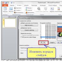 Deleting, rearranging, and adding slides
 What to do if there is no sound on the computer
 Installing animated themes in Yandex