Creating a dimension style in AutoCAD. Dimension Styles in AutoCAD AutoCAD Dimension Style Manager
In this article, we will talk about the correct work with dimensions in AutoCAD. Here are the details I will consider:
– How to put, make dimensions in AutoCAD
How to resize in AutoCAD
- How to put down an easy dimensional chain in AutoCAD
– How to scale dimensional numbers
– How to customize dimension style
– What is annotative dimension in AutoCAD
– How to add a diameter icon to a dimension number
Enjoy watching 🙂
Video version of the lesson:
Take the basic course "AutoCAD in 40 minutes" from the author, which you will find on .
Text version of the lesson:
In order to put down the usual linear size(this is a size parallel to either the X axis or the Y axis), you need to select the appropriate command on the AutoCAD Command Ribbon, in the “Home” tab, in the “Annotations” ribbon block. The command-button is called “Linear Dimension”. See picture:
And in AutoCAD the size is automatically attached to some types of objects, for example, to Polylines, to segments.
For example, you need to reduce the measured section of the part (the upper horizontal surface). If you have a part contour made by a Polyline, then it is enough to do the following:
- Select polyline
- Grasp the rectangular blue "handle" in the place indicated in the figure below. To do this, click the left mouse button once on this handle.
- Move the cursor to the left (to reduce the length of the section), and click the left button again.
As a result, as we will see, the size will automatically update - decrease:

Now let's talk about dimension style settings in AutoCAD- the most important topic, perhaps. Indeed, in the style settings, we can make texts according to GOST, serifs instead of arrows (for construction drawings), adjust the accuracy of dimensional numbers - the number of decimal places.
In order to enter the style settings, you need to expand the “Annotations” ribbon block (see the figure below), click on the “Dimensional Style” button. Next, in the pop-up window, select the name of the custom style on the left ( Dimension style in AutoCAD is a set of settings united by one name), and click the “Edit” button on the right:

Now let's learn how to quickly execute dimensional chain in AutoCAD.
To do this, there is a very magical and simple function - “Quick Size” (or “Express Size”). To call it, you need to go to the “Annotations” tab of our Team Feed, then find and click on the command with the appropriate name (see the picture below).

Also, sometimes beginners are concerned about the question -
how to put down a diameter or degree icon in dimensions in AutoCAD?
Here, too, there is really nothing complicated. Just select the desired dimensional text by double-clicking on it with the left mouse button, then in the transformed ribbon, click on the large “Designation” button to the right. After that, select the desired designation from the list - be it a diameter or a degree (or something else):

Dimensional annotation is a lifesaver for small dimensions on large construction drawings!
Builders who draw in AutoCAD are faced with the fact that if you draw a building on a scale of 1: 1 (and by the way, it’s supposed to work, see then the dimensions are not visible at all, just as serifs and arrows are not visible.
In fact, everything is very logical - your drawing is measured in meters, and the dimensional numbers and serifs are only millimeters, that is, 1000 times less. Therefore, they are not noticeable in the drawing, but they are 🙂
This is where it saves us Annotative dimensions and texts, which visually enlarges annotations - dimensions, texts and other explanatory elements of the drawing. You need to make 2 main settings in the dimension style for this:

Another great plus of annotative sizes and texts.
When drawing drawings on , no matter what scale you set for the drawing, dimensions and texts will always have the same height and will not be scaled.
Be sure to get my more detailed basic video course “AutoCAD in 40 minutes” by clicking on the picture below:
Other related lessons
In this video and tutorial, we'll show you how to work with properties in AutoCAD, as well as how the properties panel and copying works. The lesson will answer such questions: - What are Properties in AutoCAD? - How to enable the properties panel in AutoCAD? – What are quick properties and how to disable them? – How to copy properties in AutoCAD […]
In this lesson, we'll talk about how to correctly set the settings in AutoCAD according to GOST.
This applies to the following topics:
- What fonts for AutoCAD correspond to GOST;
– How to make the dimensions and texts according to GOST;
- What GOSTs are still used in the drawings;
– How to set up lines according to GOST in AutoCAD;
- How best to insert frames according to GOST in AutoCAD;
- What are the hatching according to GOST in AutoCAD.
Video version of the lesson:
Text version of the lesson:
Hello dear colleague! Despite the fact that there is a SPDS module that helps and makes life easier for the user of AutoCAD, there is always a chance that manual configuration of the program in accordance with GOST will be required. Now I'm talking about GOST sizes, GOST text, hatching and other equally important elements. I propose to immediately go to the lesson and we will start with the first question.
Question 1. How to set up hatching according to GOST in AutoCAD?
To be more precise, now we will talk about the correspondence of the samples that are in AutoCAD with the GOST symbols that should be used when
Let me explain. There are a lot of hatching patterns in AutoCAD, but not all of them correspond to GOST, so now I will show below which hatches correspond to GOST and what they mean.
Step 1. Recall that to enter the hatching mode for elements, you need to click on the special hatching command of the same name. Which is located on the “home” tab on the “drawing” panel.
Step 2 Before we start hatching objects, we must select a “sample” with which we will hatch. But let me remind you that not all “samples” correspond to our GOSTs, so remember or write down the names of the “samples” of hatching that should be used according to GOST.
Sample ANSI 31- According to GOST they designate metals.
If you make an angle of 45 degrees, then such hatching denotes a tree.

Sample ANSI 32- According to GOST they designate brick.

Sample ANSI 35- According to GOST they designate reinforced concrete.

Sample ANSI 36- According to GOST they designate concrete.

Sample ANSI 37- According to GOST they designate heaters, gypsum, etc..

Question 2. How to set up text according to GOST in AutoCAD?
Step 1. Let's go to text styles.


Step 2 We go to the desired dimensional style.

Step 3 In the “Dimension Style Changes” window, go to the “Symbols and Arrows” tab and set “double serifs” in the arrows. We do this in all three paragraphs, the first, second and callout.


Step 4 The next step is to go to the “text” tab and in the text properties, in the “text style” item, select our text style, which we set up in the second question. Thus, the font of the text for the dimensions will be in accordance with GOST.

Question 4. How to adjust the line thickness according to GOST in AutoCAD?

Step 2 To set the desired thickness for the line weight, you just need to click on the “Line weight” column next to the desired layer and set the required thickness according to GOST.

Question 5. How to set up a frame and a stamp according to GOST in AutoCAD?
The easiest way to create a frame and a stamp is through the SPDS module in AutoCAD.
Step 1. If you don't have it, download and install it. If there is, go to the SPDS tab and click on the “format” command.

Step 2 In a new window, expand the list called “Sheet Template. Working drawing of SPDS”, in it we select the sheet template we need, for example, landscape A3. We click OK.

Step 3 Choose a place to insert a frame and you will receive an already designed sheet, and with the correct stamp. This goes for any format.

Let's sum it up friends! In Russia, when designing and working with projects in AutoCAD, we must adhere to our GOSTs. Accordingly, before starting work, you should set up and set everything according to GOST, and only then proceed to create projects. We briefly discussed how to set everything up according to GOST in this lesson, but if you still have questions, feel free to ask them in the comments.
The task of how to adjust the dimensions in AutoCAD is dual. You can adjust the previously set size - you are not satisfied with its size or geometric characteristics; or create a new dimension style and use it in the future as a kind of library of dimensions of a very different nature.
We also have in mind one more nuance, the consideration of which can be very helpful in real work. The fact is that there are a great many situations and not everything can be foreseen. In other words, not everything can be included in the used dimension style. Therefore, the developer must be ready, if necessary, to create the size "manually" - AutoCAD provides all the tools for this - there are lines, and arrows, and text tools, and the ability to use special characters (often there are problems with setting diameters and radii according to the requirements of our GOSTs) .
In addition, let's not forget that when choosing a value, the program focuses on real dimensions that correspond to the selected limits of the drawing. In other words, setting dimensions in AutoCAD necessarily comes after going to the menu "Format" / "Drawing Limits" ("Format" / "Drawing Limits"). This is fundamentally important for AutoCAD - all work and display takes place with real dimensions, the developer is freed from the need to first measure, then recalculate it into points on the screen, and then enter it into the parameter of the depicted object. This kind of “old-fashioned” work is a thing of the past.
Customizing the Created Dimension
When a dimension is set, it exactly matches the general parameters set in the current working style for the specified dimension type. But the general settings do not always reflect the desired size parameters; to change them, you can call the properties of the size through the context menu of the size (in the menu window - "Properties").
The properties window can also be called through the main menu using the “Changes” / “Properties” command (“Modify” / “Properties”), using the “Properties” tool on the main toolbar or using the hot key combination - “ Ctrl+1".

Among the many possible local changes that can be made (appear immediately after the change):
- Color - color change, the color assigned to the layer is selected by default;
- Layer - transfer the size to another layer; in general, it is useful to place all sizes on a separate layer, but if you made a mistake with the data, then it is possible to transfer;
- Dim style - change the style that the size belongs to;
- Lines & Arrows - a group of "small" settings for the geometry of lines, all possible indents and the appearance of arrows;
- Text - a group of text settings - format, position, indents. Please note that by default AutoCAD sets the actual size to the limits of the drawing (indicated in a pale color in the Measurement parameter), but this value can be changed if necessary (after all, if a sketch is created, the main thing is that the dimensions are correctly set, and the graphics correspond to them not absolutely necessary). You can change the measured value using the parameter included in this group - Text override. In practice, this is one of the most frequently performed configuration tasks.
- Fit - a group of options for the relative position of lines, arrows and text, if the measured object does not allow you to set the size in a standard way - another group of frequently used settings.
Working with Dimension Styles
Strictly speaking, when they talk about setting sizes in AutoCAD, they mean a dimensional style - a library of different types of sizes created according to the requirements, for example, of one standard.
Initially, the program uses one built-in style by default - ISO-25 (specified in the "Dim Style Control" drop-down list located on the "Dimension" toolbar). This panel is not displayed by default, so the user will need to do it himself (the "View" / "Toolbars" command).
Please note that the user is given the opportunity, as necessary, to first create a dimension in one style, and then change it by choosing in the list of styles - in this way it turns out that all dimensions of the drawing are in one style, and one in another, this is a common situation.
Work with styles is performed by the “Dimension Style” command, which is located to the right of the list by default (here, as in any program, the user has the right to change both the presence of the command in the panel and its location).

When you start working with styles, you have at your disposal:
- Styles - list of available styles;
- List - selection of the list formation option - all styles or only those used;
- Set Current - setting the style selected in the list as the current working one;
- New - creating a new style based on the one selected in the list;
- Modify - style change;
- Override - redefining the style;
- Compare - compare two styles (a very useful command when you have to work with an unfamiliar drawing).
When creating a new style, it is proposed to pre-select not only the original style, but also the types of dimensions that will be created. By default, it is proposed to configure all types, but only linear, radii, diameters, angular, callouts are among the choices.

After the choice has been made, when pressing the “Continue” button, the developer has at his disposal a window with six tabs that provide for all possible settings. If any of the parameters is not entirely clear, the user will never have problems understanding it - all changes are immediately reflected in the preview window.
Among the most significant settings:

If you have the 2015-2017 version of AutoCAD at your disposal, then the drop-down list of dimension styles is placed here on the Annotation panel.
As you can see, setting the dimensions is a rather troublesome business - several dozens of various parameters - but on the other hand, it is fascinating, everything is organized very conveniently, the purpose of each is either described or immediately reflected in the example after use.
This is not to say that you often have to create new dimensional styles, usually the default ISO-25 is enough, but in especially “thin” situations you can’t do without size settings, and you need to remember them.
This note shows a detailed example of how to create and set up a dimension style in AutoCAD. The program setting of each option of each tab of the dialog box for editing dimension styles is considered.
The result of the code below (the CreateDimStyle command) will look like this:
In the code, each setting option that we change is marked with a comment containing the name of this option in the English version of AutoCAD.
/* DimStyleSample.cs * © Andrey Bushman, 2014 * An example of creating and setting a dimension style.*/ using System; using cad = Autodesk.AutoCAD.ApplicationServices .Application ; using Ap = Autodesk.AutoCAD.ApplicationServices; using Db = Autodesk.AutoCAD.DatabaseServices; using Ed = Autodesk.AutoCAD.EditorInput; using Rt = Autodesk.AutoCAD.Runtime; using Clr = Autodesk.AutoCAD.Colors; //************************************ namespace Bushman.CAD.Samples.Styles ( public class DimStyleSample ( public void CreateDimStyle() ( Ap.Document doc = cad .DocumentManager .MdiActiveDocument; if (doc == null ) return ; Ed.Editor ed = doc.Editor; Db. Database db = doc.Database;using(Db.Transaction tr = db.TransactionManager.StartTransaction()) ( // Create a new text style for // use it in our dimensional// styles Db.TextStyleTable tst = (Db.TextStyleTable )tr.GetObject(db.TextStyleTableId, Db.OpenMode .ForWrite); Db.TextStyleTableRecord textStyle = new Db.TextStyleTableRecord(); textStyle.Name = "Type A straight" ; textStyle.FileName = "Arial.ttf" ; textStyle.XScale = 0.75; tst.Add(textStyle); tr.AddNewlyCreatedDBObject(textStyle, true ); // Create a new dimension style... Db.DimStyleTable dst = (Db.DimStyleTable )tr.GetObject(db.DimStyleTableId, Db.OpenMode .ForWrite); Db.DimStyleTableRecord dimStyle = new Db.DimStyleTableRecord(); dimStyle.Name = "Basic without permits"; // Open the "Modify" dialog // Dimension Style" (_DIMSTYLE command) and // click the "Modify.." button - we will // programmatically change these settings. // Names of tabs, settings groups and // specific options will be given for // English version of AutoCAD. // *** LINES Tab *** // "Dimension lines" settings group: Db.ObjectId lineTypeId = // db.ContinuousLinetype; // or by block: db.ByBlockLinetype; // color "ByLayer" Clr.Color colorByLayer = Clr.Color .FromColorIndex(Clr.ColorMethod .ByLayer, 256); // Assign color to dimension lines// "ByLayer" dimStyle.Dimclrd = colorByLayer; // Color // Linetype dimStyle.Dimltype = lineTypeId; // Lineweight dimStyle.Dimlwd = Db.LineWeight .ByLineWeightDefault; // Extend Beyond Ticks dimStyle.Dimdle = 2; dimStyle.Dimdli = 7; // Baseline Spacing // Suppress dim line 1 dimStyle.Dimsd1 = false ; // Suppress dim line 2 dimStyle.Dimsd2 = false ; // Settings group "Extension Lines": dimStyle.Dimclre = colorByLayer; // Color // Linetype Ext 1 dimStyle.Dimltex1 = lineTypeId; // Linetype Ext 2 dimStyle.Dimltex2 = lineTypeId; dimStyle.Dimlwe = Db.LineWeight .ByLineWeightDefault; // Lineweight // Suppress Ext line 1 dimStyle.Dimse1 = false ; // Suppress Ext line 2 dimStyle.Dimse2 = false ; // Extend Beyond Dim Lines dimStyle.Dimexe = 2.0; // Offset From Origin dimStyle.Dimexo = 0; // Fixed Length Extension Lines dimStyle.DimfxlenOn = false ; dimStyle.Dimfxlen = 1; // Length // *** SYMBOL AND ARROWS tab ***// "Arrowheads" group: // Warning: Annotative blocks cannot // be used as // custom option for options // First, Second and Leader. In designated // options custom option // represented as a "User" element // Arrow..." at the very bottom of the dropdown// list. Db.BlockTable bt = (Db.BlockTable )tr .GetObject(db.BlockTableId, Db.OpenMode .ForRead); // Get the identifiers of those of interest // us block definitions Db.ObjectId id1 = GetArrowObjectId_dim("DIMBLK1" , "_DOT" ); Db.ObjectId id2 = GetArrowObjectId_dim("DIMBLK2" , "_CLOSED" ); Db.ObjectId id3 = GetArrowObjectId_dim("DIMBLK2" , "_Oblique" ); // Make sure you set it to true // value of the "Dimsah" property, if you // must be assigned to the First and Second options // different values! dimStyle.Dimsah = true ; // As value of group options // Arrowheads you can assign // Db.ObjectId.Null - in this case it will be // use the default marker. // "First" option on the "Symbols and // Arrows" (Dimblk1 system variable) dimStyle.Dimblk1 = id3; // "Second" option on the "Symbols and // Arrows" (Dimblk2 system variable) dimStyle.Dimblk2 = id3; // Optionally, you can change both // parameter (First and Second) // at the same time, setting the property value // Dimblk. But in this case you shouldn't // assign values to properties in code// "Dimblk1" and "Dimblk2": // dimStyle.Dimblk = id3; // Leader option. If as a value // specify ObjectId.Null, it will be // use "Closed filled" option dimStyle.Dimldrblk = Db.ObjectId .Null; dimStyle.Dimasz = 3; // ArrowSize // Group "Center marks":// "Dimcen": // 0 - None; // 1 - Mark; // -1 - Line Int32 centerMarks = -1; Double centerMarksSize = 2.0; // Size of center marker or // central line dimStyle.Dimcen = centerMarks * centerMarksSize; // "Dimension Break" option value // stored in extended data (XData) // dimension style. Let's get to// him... // First, get a table of names // registered applications Db.RegAppTable regTable = (Db.RegAppTable )tr.GetObject(db.RegAppTableId, Db.OpenMode .ForRead); String xName = "cad_DSTYLE_DIMBREAK" ; // If the element we need is not // registered - execute it// registration if (!regTable.Has(xName)) ( regTable.UpgradeOpen(); Db.RegAppTableRecord app = new Db.RegAppTableRecord (); app.Name = xName; regTable.Add(app); tr.AddNewlyCreatedDBObject(app , true ); ) Db.ResultBuffer rb = new Db.ResultBuffer (new Db.TypedValue ((Int32 )Db.DxfCode .ExtendedDataRegAppName, xName), new Db.TypedValue ((Int32 )Db.DxfCode .ExtendedDataInteger16, 391), new Db.TypedValue ((Int32 )Db.DxfCode .ExtendedDataReal, 0.0 /* Our "Dimension" property value* Break" */ )); dimStyle.XData = rb; // Group (optional) "Arc Length Symbol": // Valid values for the property // "Dimarcsym" (three switches): // 0 - Precending dimension text// 1 - Above dimension text // 2 - None // Option "Arc Length Symbol" dimStyle.Dimarcsym = 1; // Group "Radius Jog Dimensions":// Jog Angle dimStyle.Dimjogang = 45 * Math.PI / 180; // Group "Linear Jog Dimensions": // "Linear Jog Size" value is stored in // extended data (XData) dimensional// style. xName = "cad_DSTYLE_DIMJAG" ; if (!regTable.Has(xName)) ( regTable.UpgradeOpen(); Db.RegAppTableRecord app = new Db.RegAppTableRecord (); app.Name = xName; regTable.Add(app); tr.AddNewlyCreatedDBObject(app, true ) ; ) rb = new Db.ResultBuffer (new Db.TypedValue ((Int32 )Db.DxfCode .ExtendedDataRegAppName, xName), new Db.TypedValue ((Int32 )Db.DxfCode .ExtendedDataInteger16, 388), new Db.TypedValue ((Int32 )Db.DxfCode .ExtendedDataReal, 1.4995 /* Value for the "Linear Jog" property* Size" */ )); dimStyle.XData = rb; // *** TEXT Tab *** // Group "Text Appearance":// Text Style dimStyle.Dimtxsty = textStyle.ObjectId; dimStyle.Dimclrt = Clr.Color .FromColorIndex(Clr.ColorMethod .ByAci, 210); // Text Color // The "Dimtfill" property affects // behavior of the "Fill Color" option and // takes one of the following values: // 0 - no background // 1 - Use current drawing background // 2 - Background specified in the property// Dimtfillclr. dimStyle.Dimfill = 0; dimStyle.Dimtfillclr = Clr.Color .FromColorIndex(Clr.ColorMethod .ByAci, 256); // Fill Color (see Dimtfill above) dimStyle.Dimtxt = 3.5; // Text Height // Fraction Height Scale dimStyle.Dimfrac = 2; // Enable\Disable the option "Draw Frame// Around Text" Boolean drawFrameAroundText = false ; // Group "Text Placement": // Vertical option ("Dimtad" property) // can only accept the following// values: // 0 - Centered: center the dimension // text between extension lines. // 1 - Above: place dimension text // above the dimension line, behind // except when // dimension line is not horizontal and // text inside extension lines is placed // horizontal (DIMTIH = 1). // Distance from dimension line to // the bottom line of text // determined by the value of the variable // DIMGAP (Dimgap property). // 2 - Outside: place dimension // text away from the dimension line, // away from certain points. // 3 - JIS: place dimension text in // according to Japanese // Industry Standard. dimStyle.Dimtad = 1; // Vertical // Horizontal option ("Dimjust" property) // accepts only the following values:// 0 - Centered // 1 - At Ext Line 1 // 2 - At Ext Line 2 // 3 - Over Ext Line 1 // 4 - Over Ext Line 2 dimStyle.Dimjust = 0; // Horizontal // View Direction #if NEWER_THAN_2009 dimStyle.Dimtxtdirection = true;#endif // Offset from Dim Line dimStyle.Dimgap = 1 * (drawFrameAroundText ? -1: 1); // Group "Text Alignment": // To choose one of the three // available options, should be assigned // value for two properties at once: Dimtih// and Dimtoh. // // Horizontal: // Dimtih = true; // Dimmoh = true; // // Aligned with Dimension Line:// Dimtih = false; // Dimth=false; // // ISO Standard: // Dimtih = false; // Dimmoh = true; // // Text Alignment dimStyle.Dimtih = false ; dimStyle.Dimtoh = false ; // *** FIT Tab *** // Group "Fit Options": // The "Dimatfit" property can take // 0 - Select Both text and arrows option // 1 - Select the Arrows option // 2 - Select option Text // 3 - Select the option "Either text or// arrows (best fit)" // To assign to a property // "Dimatfit" desired value 0-3, needed // first assign false to the property // Dimtix. If Dimtix is set to true, then // the "Always Keep Text" option will be selected// Between Ext Lines". // Option "Always Keep Text Between Ext// Lines" dimStyle.Dimtix = false ; // Don't forget to pre-set// "Dimtix" to false dimStyle.Dimatfit = 3; // Suppress Arrows If They Don't Fit// Inside Extension Lines dimStyle.Dimsoxd = false ; // "Text placement" group: // The Dimtmove property can take // only the following values: // 0 - "Beside the// dimension line" // 1 - "Over dimension" option selected// line, with leader" // 2 - "Over dimension" option selected// line, leader without" dimStyle.Dimtmove = 1; // "Scale for Dimension Features" group: dimStyle.Annotative = Db.AnnotativeStates .True; // Annotative dimStyle.Dimscale = 1.0; // Dimscale // To set an option // "Scale Dimensions To Layout" needs // set the Dimscale property to 0:// dimStyle.Dimscale = 0; // Group "Fine Tuning":// Place Text Manually dimStyle.Dimupt = false ; // Draw Dim Line Between Ext Lines dimStyle.Dimtofl = false ; // *** Primary Units tab *** // Group "Leader dimensions" // Option "Unit format" (property // "Dimlunit") can only accept // the following values:// 1 - Scientific // 2 - Decimal // 3 - Engineering // 4 - Architectural // 5 - Fractional // 6 - Windows Desktop // Unit format dimStyle.Dimlunit = 2; // Height Scale Factor // text written as a fraction. This // height is calculated by multiplying // coefficient specified in the Dimtfac property // point to the height of the text specified in// property Dimtxt. dimStyle.Dimtfac = 0.5; // A number of simbols after comma: dimStyle.Dimdec = 0; // Precision // Option "Fraction format" (property // "Dimfrac") accepts one of the following// values: // 0 - Horizontal // 1 - Diagonal // 2 - Not stacked (e.g. 1/2) dimStyle.Dimfrac = 0; // Fraction Format // If options "Unit format" as // values assigned to "Decimal", then the current // one hundred sizes, instead of a dot, as // decimal separator will be // use a different delimiter, which // ry is specified using a property // "Dimdsep". If the "Dimdsep" property // assign NULL as a value, then // as decimal separator // dot will be used. // Option "Decimal separator" (property // "Dimdsep") can only accept // the following values:// "." - Period // "," - Comma // " " - Space // Decimal Separator dimStyle.Dimdsep = "," ; dimStyle.Dimrnd = 0.0; // Round Off // assigned to the Dimpost property.// Example: "L=<> // <> // "m" - suffix dimStyle.Dimpost = "<>" ; // Group "Measurement Scale": dimStyle.Dimlfac = 1; // Scale Factor // Select or deselect an option // "Apply to Layout Dimensions Only" on // "Primary Units" tab: Boolean applyToLayoutDimensionsOnly = false ; // If the "Dimfrac" property is assigned // negative value, then option // "Apply to Layout Dimensions Only" // will be included: dimStyle.Dimlfac = applyToLayoutDimensionsOnly ? -1 * Math .Abs(dimStyle.Dimlfac) : Math .Abs(dimStyle.Dimlfac); // Subgroup "Zero Suppression" group// "Leader dimensions": // The "Dimzin" property" should// feet and inches // feet and inches // for inches // for feet // written as,5000) // written as 12.5)// like,5) dimStyle.Dimzin = 8; #if NEWER_THAN_2009 // dimension style named "DIMMZF" and// "DIMMZS" #endif // "Angular Dimensions" group: // Options "Units format" (property // "Dimaunit) should be assigned one of // the following values:// 0 - Decimal degrees // 1 - Degrees/minutes/seconds// 2 - Gradians // 3 - Radians dimStyle.Dimaunit = 1; // Units Format // Precision option ("Dimadec" property) // must contain one of the following// values: // -1 - Displayed in angular dimensions // a number of simbols after comma, // specified using a variable// DIMDEC. // 0-8 - Indicates the number of characters // after the comma displayed in // angular dimensions (regardless of // DIMDEC variable) dimStyle.Dimadec = 4; // Precision // groups "Angular Dimensions" controls // zero suppression for all corners// sizes. // "Dimazin" property should contain // one of the following values: // 0 - Displays all leading and trailing// all zeros. // 1 - Suppresses leading zeros in decimal // new dimensions (for example, 0.5000 // written as,5000) // 2 - Suppresses trailing zeros in // decimal sizes (for example, // 12.5000 is written as 12.5) // 3 - Suppression of leading and trailing // zeros (for example, 0.5000 writes-// as,5) dimStyle.Dimazin = 2; // *** ALTERNATIVE UNITS tab ***// Display Alternate Units dimStyle.Dimalt = false ; // "Alternate Units" group: // Option "Unit Format" (property // "Dimaltu") must contain one of // the following values:// 1 - Scientific // 2 - Decimal // 3 - Engineering // 4 - Architectural Stacked // 5 - Fractional Stacked // 6 - Architectural // 7 - Fractional // 8 - Windows Desktop dimStyle.Dimaltu = 2; // Unit Format dimStyle.Dimaltd = 0; // Precision // Multiplier for Alternate Units dimStyle.Dimaltf = 25.4; // Round Distances To dimStyle.Dimaltrnd = 0; // Prefix (prefix) and Suffix (suffix) // Prefix and suffix are specified in // as part of a string value, // assigned to the Dimapost property.// Example: "L=<>m" // Where: // "L = " - prefix // <>- computed numeric value// "m" - suffix dimStyle.Dimapost = "<>" ; // Group "Zero Suppression": // "Dimaltz" property" should be // assign one of the following values: // 0 - Suppresses null values for// feet and inches // 1 - Writes zero values for// feet and inches // 2 - Writes null values for // feet and suppresses null values// for inches // 3 - Writes null values for // inches and suppresses zero values// for feet // 4 - Suppresses leading zeros in decimal // new dimensions (for example, 0.5000 // written as,5000) // 8 - Suppresses trailing zeros in decimal // exact sizes (e.g. 12.5000 // written as 12.5) // 12 - Suppresses both leading and trailing // zeros (for example, 0.5000 is written// like,5) dimStyle.Dimaltz = 0; // Zero Suppression // If leading null suppression is enabled // leu, then become available for // edit option "Sub-units // factor" and "Sub-units suffix".#if NEWER_THAN_2009 // TODO: Code author failed to program- // but get to these properties, because // no variables and properties exist // dimension style named "DIMALTMZF"// and "DIMALTMZS". #endif // Group "Placement": const String bpv = @"\X" ; // Toggle options for this group // performed by appending or // remove the "\X" suffix from the value// Dimpost properties: // If you need to select the option "Below// primary value": // dimStyle.Dimpost = dimStyle.Dimpost // .EndsWith(bpv) ? dimStyle.Dimpost:// dimStyle.Dimpost + bpv; // If you need to select the option "After// primary value": dimStyle.Dimpost = !dimStyle.Dimpost .EndsWith(bpv) ? dimStyle.Dimpost: dimStyle.Dimpost.Substring(0, dimStyle.Dimpost.Length - bpv.Length); // *** Tolerances tab *** // Group "Tolerance Format": // Dimtol = true, Dimlim = true - // "Limits", but don't set this // combinations(!!!), or you will get // "Style Overrides" for Dimension // style name. For getting the // "Limits" value, look below.// // Symmetrical: // Dimtol = true // Dimlim = false // // Limits (recommended):// Dimtol = false // Dimlim = true // // None: // Dimtol = false // Dimlim = false // // Basic: // dimStyle.Dimgap = -1 * Math.Abs(// dimStyle.Dimgap); // // Deviation: // Dimtol = true // Dimtm = 1.0e-009 dimStyle.Dimtol = false ; dimStyle.Dimlim = false ; dimStyle.Dimtdec = 0; // Precision dimStyle.Dimtp = 1; // Upper Value dimStyle.Dimtm = 0; // Lower Value // Scaling for Height dimStyle.Dimtfac = 0.5; // Option "Vertical Position" (property // "Dimtolj") must take one of // the following values:// 0 - Bottom // 1 - Middle // 2 - Top // Vertical Position dimStyle.Dimtolj = 1; // Group "Tolerance Alignment": // TODO: Code author failed to change // state of switches "Align // Decimal Separators" and "Align// Operational Symbols" // Subgroup "Zero Suppression" in the group// "Tolerance Format": // "Dimtzin" property"s allowed values: // 0 - Suppresses null values for// feet and inches // 1 - Writes zero values for// feet and inches // 2 - Writes null values for // feet and suppresses null values// for inches // 3 - Writes null values for // inches and suppresses zero values// for feet // 4 - Suppresses leading zeros in decimal // new dimensions (for example, 0.5000 // written as,5000) // 8 - Suppresses trailing zeros in decimal // exact sizes (e.g. 12.5000 // written as 12.5) // 12 - Suppresses both leading and trailing // zeros (for example, 0.5000 is written// like,5) dimStyle.Dimtzin = 8; // Zero Suppression // Group "Alternate Unit Tolerance": dimStyle.Dimalttd = 0; // Precision // Subgroup "Zero Suppression" in the composition // groups "Alternate Unit Tolerance": // "Dimalttz" property "s allowed values: // 0 - Suppresses null values for// feet and inches // 1 - Writes zero values for// feet and inches // 2 - Writes null values for // feet and suppresses null values// for inches // 3 - Writes null values for // inches and suppresses zero values// for feet // // To suppress leading or trailing // zeros to the selected value can be// added: // // 4 - Suppress leading zeros // 8 - Suppression of trailing zeros.// Zero Suppression dimStyle.Dimalttz = 0; // *** // Save the changes made dst.Add(dimStyle); tr.AddNewlyCreatedDBObject(dimStyle, true ); // Eliminate the potential // the problem of appearance in the list of dimensional // additional element styles, // named as "Style Overrides": db.Dimstyle = dimStyle.ObjectId; db.SetDimstyleData(dimStyle); // Now, based on the base we created // new dimension style, you can create // its detailed options for: // - radial dimensions // - angular dimensions // - linear dimensions// - etc. // For more information, you can // read the documentation section: // ObjectARX Reference Guide > Additional // Information > Dimension Styles >// Dimension Style Families. // Child dimension styles are created on // based on base. Names are formed according to // rule: BaseStyleName + Suffix. // One is used as suffixes // from the following options: String names = new String ( "$0" , // Linear "$2" , // Angular "$3" , // Diametrical "$4" , // Radial "$6" , // Ordinal "$7" // Callouts ); foreach (String item in names) ( Db.DimStyleTableRecord childStyle; String childName = dimStyle.Name + item; if (dst.Has(childName)) ( childStyle = (Db.DimStyleTableRecord )tr .GetObject(dst, Db.OpenMode .ForWrite ); ) else ( childStyle = (Db.DimStyleTableRecord )dimStyle .Clone(); childStyle.Name = childName; dst.Add(childStyle); tr.AddNewlyCreatedDBObject(childStyle, true ); ) ) // Next, you can configure // inherited dimension styles, // thus fulfilling the necessary // detailing for specific types// sizes. // Editing is done exactly like this // same as we did above with the base // with your style, so in our example // let's not repeat this one // finish the job. tr Commit(); ) ) static Db.ObjectId GetArrowObjectId_dim(string arrow, string newArrName) ( Db.ObjectId arrObjId = Db.ObjectId .Null; Ap.Document doc = cad .DocumentManager .MdiActiveDocument; Db.Database db = doc.Database; string oldArrName = cad .GetSystemVariable(arrow) as string ; // (this operation can create in the drawing // new block definition) cad .SetSystemVariable(arrow, newArrName); // Restore previous value if (oldArrName.Length != 0) cad .SetSystemVariable(arrow, oldArrName); // Get block ID Db.Transaction tr = db.TransactionManager.StartTransaction(); using (tr) ( Db.BlockTable bt = (Db.BlockTable )tr .GetObject(db.BlockTableId, Db.OpenMode .ForRead); arrObjId = bt; tr.Commit(); ) return arrObjId; ) ) )
The detail drawing is unacceptable without the dimensions applied to it. Dimensions must fully determine the size of the product. There should be a sufficient number of them, but it is also not necessary to apply extra sizes.
The dimensions in the drawing can be linear, angular, radial. And I also advise you to read the article "" Linear dimensions determine the length, width, height of the product and are indicated in millimeters without indicating the unit of measurement. Angular dimensions are measured in degrees, minutes, seconds with the designation of the unit of measurement. Radial dimensions indicate the length of radii or diameters of arcs and circles. The size consists of:
- Extension lines drawn perpendicular to the line being measured. Extension lines of angular dimensions are drawn radially, and when drawing the size of an arc, perpendicular to its chord or radially.
- Dimension lines drawn parallel to a segment, the size of which is determined at a distance of at least 10 mm from the contour of the part. The ends of the dimension lines are limited by arrows, notches or dots. The extension lines go beyond the dimensional ones by 1 - 5 mm. When drawing multiple parallel dimension lines, the smaller dimension is applied closer to the contour. Dimension lines of angular dimensions are arcs centered at the corner or arc vertex.
- Dimensional numbers that indicate the size of the product.
Depending on the product and the orientation of the extension lines, the dimensions can be horizontal, vertical, parallel, rotated, ordinate. You can set dimensions from a common base and form dimensional chains.
Dimensioning can be done using one of two methods. The first is that after the command is entered, the mouse cursor indicates the object whose size is measured and the position of the dimension line is set. When using the second method, the mouse cursor indicates the starting points of extension lines and the position of the dimension line. In the latter case, it is recommended to enable the object snap mode.
Options for applying dimensions or editing them are contained in the menu command Dimension, as well as in the form of buttons on the panel Dimension.
AutoCAD creates associative dimensions. Associativity lies in the fact that when objects are changed by editing commands, dimension elements are automatically updated. 
The appearance of the dimension in the drawing depends on the selected style. The default style is ISO-25, intended for mechanical drafting. AutoCAD provides the ability to modify existing styles as well as create your own styles. The selected dimension style determines the display of extension lines, the size and position of the text, the length and type of arrows, the basic spacing between dimension lines, etc. Dimensionstylemanager. Making changes to an existing style occurs in the dialog box Modyfy Dimension Style. On the corresponding tabs of this window, you can change the value of dimensional variables. The window is called by pressing the button Modify in the window Dimensionstylemanager.

Click to create a new style. New in the window Dimensionstylemanager in field NewstyleName enter a name for the style and click the button. Then on the window tabs Modyfy Dimension Style set dimensions.

On the tab line and tab SymbolsandArrows color, thickness and other characteristics of dimension and extension lines are set. Choose the type and size of the arrows. On the same tab, you can choose whether or not to display markers in the center of the circle, as well as their size.
On the tab Text Dimensional text parameters are selected: color, style, alignment.
On the tab fit the mutual placement of dimension, extension lines and text, as well as the scale of dimensions, is controlled.
On tabs Primary Units And Alfernate Units the format of the units of measure is determined, the accuracy is set.
On the tab tolerance the format and accuracy of tolerances are determined.
Drawing linear dimensions
Linear dimensions can be horizontal, vertical, ordinate, form stable chains, or can be plotted from a common base. DIMLINEAR (DLI) Command (Linear) Command entry methods:
Enter the command in one of the following ways. The system will prompt: Specify first extension line origin or
- mtext. A multi-line text editor window will open. Multiline Text Editor, where you can make changes to the dimension text. Angle brackets< >designate the dimensional number defined by the system.
- Text. Allows you to make changes to the dimension text using the single line text editor. When making changes, you can type certain sequences of characters to insert a diameter sign (%%c) before the dimension number, insert a degree sign (%%d) into the text, etc.
- Angle. You can change the angle of the dimension number or dimension text. After selecting this option, the system will prompt you for the angle value: Specifyangleofdimensiontext:
- Horizontal. Used to draw a horizontal dimension. The system will prompt you for the position of the dimension line: Specify dimensionlinelocationor[mtext /Text /Angle] :
- Vertical. Used for vertical dimensioning. The system will prompt you for the position of the dimension line: Specifydimensionlinelocationor[mtext /Text /Angle] :
- Rotated(Turned). It is used if it is necessary to set the angle of inclination of the dimension line. The system will prompt you for the angle value: Specifyangleofdimensionline<0 > : and a query regarding the position of the dimension line: Specify dimensionlinelocationor[mtext /Text /Angle] :
Dialogue when applying a rotated dimension:
When dimensioning, AutoCAD draws extension lines perpendicular to the dimension line. However, if the extension lines impair the readability of other elements of the drawing, the angle of their inclination can be changed after the dimension has been created.
To change the slope of extension lines:
1. Build a linear dimension.
2. From the menu Dimension choose Oblique.
3. Choose a size or sizes. Click ENTER.
4. Enter a value for the angle of inclination or pick two points.
This command draws a dimension line whose inclination angle coincides with the inclination angle of the selected object. The size is applied in the same way as a linear one.

DIMBASELINE Command (DBA) (Basic) Command entry methods:
A number of dimensions (linear, angular, ordinate) are applied from a common base. The first extension line of the size set by the preliminary command is taken as the base line, or you can select another base line. There is no prompt regarding the position of the dimension line because the base spacing is determined by the dimension style. The command is executed when at least one dimension is applied to the drawing, any of the commands DIMLINEAR, or DIMANGULAR.
The system supports the following dialogue:

DIMCONTINUE Command (Continue) Command entry methods:
The command creates a dimension chain in which the second extension line of the previous dimension is the starting point for the dimension that is being placed. Dimension lines belong to one straight line and requests for their position are not issued. The operation of the command is similar to that of the previous command.

Command DIMORDINATE (Ordinate) Command entry methods:
Ordinate dimensions indicate the X or Y coordinates of points relative to the base point. The base point is usually the lower left corner of the part. The center of the coordinate system before placing ordinate dimensions can be moved to the base point with the command UCS with option New. The ordinate dimension sets the distance of a point to the base point, respectively, along the X axis or along the Y axis and consists of an extension line and a distance value. Along which axis to set the distance value, the system determines automatically.
To apply a coordinate dimension, enter the command in one of the ways, and then maintain the dialogue:

Applying Radial Dimensions
The size of an arc or circle is determined by the value of the radius or diameter. For these objects, it is also possible to apply center markers and centerlines. Command DIMDIAMETER (Diameter) Command entry methods:
To draw the diameter, enter the command in one of the ways. On request: Select arc or circle: show any point of the object as an intersection. AutoCad allows you to create a dimension line of arbitrary length and place it at any angle. Using the command options, you can edit the dimension text, as well as change the angle of its inclination. AutoCad automatically inserts a symbol before the diameter value. The dimension line for a given dimension must not be vertical or horizontal.
DIMRADIUS Command (Radius) Command entry methods:
Drawing a radius is carried out similarly to drawing a diameter. AutoCad automatically inserts an R in front of the radius value.

Applying angular dimensions
Angular dimensions can be determined for an arc, two segments, three points that do not belong to a straight line. The angular dimensions are displayed with the designation of the unit of measure o (degree). The dimension line of an angular dimension is an arc centered at the corner vertex; extension lines are generated automatically. Angular dimensions can be applied from a common base, as well as create a dimensional chain. Team DIMANGULAR (Angular) Command entry methods:
Applying angular dimensions is accompanied by a dialog:
| Command: _dimangular | Team Angular. |
| Select arc, circle, line, or |
Specify an arc, circle, line, or<параметр по умолчанию>: This choice determines which requests the system will issue next. |
| Select second line: | Specify the second line. |
| Specify dimension arc line location or : m | Define the position of the dimension line or select an option. Select function mtext to edit dimension text. |
| Specify dimension arc line location or: | Determine the position of the dimension line. |
| Dimension text = 36 | The system returns the value of the dimension text. |

This concludes the study of sizing methods. And in the next lesson we will talk about.
 How to open RTF? How to open a .RTF file? What's in RTF files
 How to set the background and text color on a web page?
 How to make a background in an open office presentation How to change the background of a presentation in openoffice
 Data Validity Check
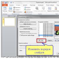 Deleting, rearranging, and adding slides
 What to do if there is no sound on the computer
 Installing animated themes in Yandex