An example of the CNC control program. Writing CNC programs free learning for beginners. Writing a simple managing program
In fig. 2.21. Definition of the coordinate axes of the CNC machine with the help of the right hand: the thumb is the axis H., index finger - axis W., middle finger - axis Z.. To determine the coordinate movements of the machine, the rear side mentally placed on the processed plane of the workpiece so that the semitted middle finger coincides with the axis of rotation of the tool.
|


CNC Machine Permanent Cycles
Fig. 8.8. It is necessary to drill 7 holes with a diameter of 3 mm and a depth of 6.5 mm
Example number 2.

Fig. 8.9. It is necessary to drill 12 holes with a diameter of 5 mm and a depth of 40 mm, to pre-perform the operation of centering holes
| Program code | Description |
| % O0002 (Program Name - Holes2) N100 G21 N102 G0 G17 G40 G49 G80 G90 (CENTROVKA) N104 T1 M6 N106 G54 X21.651 Y12.5 S1200 M3 N108 G43 H2 Z100. N110 Z2. N112 G99 G81 Z-.8 R2. F70. N114 x12.5 y21.651 N116 x0. Y25. N118 X-12.5 Y21.651 N120 X-21.651 Y12.5 N122 X-25. Y0. N124 X-21.651 Y-12.5 N126 X-12.5 Y-21.651 N128 X0. Y-25. N130 x12.5 Y-21.651 N132 X21.651 Y-12.5 N134 X25. Y0. N136 G80 N138 Z100. N140 M5 N142 G91 G28 Z0. N144 G28 X0. Y0. N146 M01 (DRILL 12 HOLES) N148 T2 M6 N150 G54 X21.651 Y15.5 S1000 M3 N152 G43 H3 Z100. N154 Z2. N156 G99 G83 Z-40. R2. Q2. F45. N158 x12.5 y21.651 N160 x0. Y25. N162 X-12.5 Y21.651 N164 X-21.651 Y12.5 N166 X-25. Y0. N168 X-21.651 Y-12.5 N170 X-12.5 Y-21.651 N172 X0. Y-25. N174 x12.5 y-21.651 N176 x21.651 Y-12.5 N178 x25. Y0. N180 G80 N182 Z100. N184 M5 N186 G91 G28 Z0. N188 G28 X0. Y0. N190 M30% | Program number Program name Work in the metric system Safety string Comment Calling centering Move to the opening No. 1 Compensation of the tool length The accelerated movement to Z2. Standard Drilling Cycle Centering Hole No. 2 Centering Hole No. 3 Centering Hole No. 4 Centering Hole No. 5 Centering Hole No. 6 Centering Hole No. 7 Centering Hole No. 8 Centering Hole No. 9 Centering Hole No. 10 Centering Hole No. 11 Centering Hole No. 12 Cancellation of the Permanent Cycle Move to Z100. Stop the spindle Returns to the initial position by z Return to the original position by X, Y Temporary Stop Comment Calling the drill with a diameter of 5 mm Move to the opening No. 1 Compensation of the tool length Express movement to Z2. Cycle of Intermittent Drilling Drilling of the Hole No. 2 Drilling of the Hole No. 3 Drilling of the Hole No. 4 Drilling of the Hole No. 5 Drilling of the Hole No. 6 Drilling of the Hole No. 7 Drilling of Hole No. 8 Drilling of the Hole No. 9 Drilling of Hole No. 10 Drilling of the Hole No. 11 Drilling of Hole No. 12 Cancel of the Permanent Cycle Move to z100. Stop the spindle return to the original position by z Return to the starting position by X, Y End of the program |
planetacam.ru.
2.17. Example Managing Program for Processing
details "Threaded Roller"
In fig. 41 presented a combined drawing of the workpiece and details of the "threaded roller" with the trajectories of movement of cutting tools for processing on the machine 16A20F3, equipped with the CNC system 2p22.

Fig. 41. Scheme of processing detail "Roller threaded"
The control program for processing the detail "Threaded roller" has the following form:
| N001 T1S3 572 F0.43 m08 | Cutter T1 - rough, third range, N \u003d 572 rpm, S \u003d 0.43 mm / O, SLOV. |
| Approach to the starting point for the L08 cycle. |
|
| N003 L08 A1 P4 | The setting of the cycle L08, the allowance for the first processing is 1 mm per diameter, the depth of cutting is 4 mm. |
| Description Contour Details. |
|
| N011 S3 650 F0,2 | Changing the mode n \u003d 650 rpm, s \u003d 0.2 mm / vol. |
| The initial point in front of the black end of the end. |
|
| Condition of the face of the blacks around the cycle L05. |
|
| N014 T3 S3 1000 F0,12 | Cutter T3 - pure, third range, n \u003d 1000 rpm, S \u003d 0.12 mm / vol. |
| The approach to the starting point for the L10 cycle. |
|
| Setting the constancy of cutting speed. |
|
| Setting the loop loop L10, description of the part with the N004 frame. |
|
| Canceling consistency of cutting speed. |
|
| The initial point before finishing the end. |
|
| Finishing end of the end. |
|
| Tire removal from the end along the z axis by 0.5 mm. |
|
| Cutter's rise to the start point of the chamfer 2 × 45 °. |
|
| Chamfering chamfer 2 × 45 °. |
|
| N024 T5 S3 600 F0,25 | Cutter T5 - groove, third range, n \u003d 600 rpm, s \u003d 0.25 mm / vol. |
| N025 x32 Z-35 E | The starting point before pulling the groove. |
| Cleaning the groove to Ø20 mm. |
|
| The output of the cutter from the groove is accelerated. |
|
| N028 T7 S3 720 F0.3 | Cutter T7 - \u200b\u200bthreaded, third range, n \u003d 720 rpm, s \u003d 0.3 mm / vol. |
| The starting point of the cycle before cutting the thread. |
|
| N030 L01 F1.5 W-33.5 A0 X22.08 P0, s C0 | Cycle L01 cutting thread M24 × 1.5. |
| Coolant shutdown. |
|
| End of the management program, return to I.T. |
3. Work on machines equipped with CNC system 2p22
3.1. Remote Control
To set the operating modes of the CNC device 2P22, manual data entry, editing programs, the dialogue with the device is designed to the control panel, made in the form of a remote unit installed on the rotating machine console. The control panel keyboard is shown in Fig. 17, but the purpose of the keys is in Table. 3.
The functions performed mainly and the auxiliary modes of operation of the CNC 2P22 device are shown in Table. 7.
Table 7.
CNC 2P22 device modes
| Operating mode |
||
| main | auxiliary |
|
| Processing Details on the control program | "Automatic" mode
| |
| Processing Details on the control program with stops at the end of the frame | "Automatic" mode
| "Handset" mode
|
| Drawing up a sample program, set and testing of individual frames | "Manual" mode
| |
| Binding the reference system | "Manual" mode
| "Exit to a fixed point of the machine"
|


Continuation of table. 7.
| Semi-automatic input to the memory of floating zero and tool departures | "Manual" mode
|
|
| Semi-automatic input in memory of the initial position | "Manual" mode
| Mode "Semi-automatic entry of constants"
|
| Start-up | "Manual" mode
| Mode "Exit in initial position"
|
| Entering the control program from the control panel, indication and editing of programs | "Enter" mode
| |
| Enter, indication and editing of the tool, floating zero, starting position, machine parameters | "Enter" mode
| Mode "Enter Constant"
|
| Finding the required number of the frame of the technological program and its indication | "Enter" mode
| Mode "Frame Search" |
| Entering a technological program with a magnetic tape | "Enter" mode
|
|
| Entering a technological program with punctuents | "Conclusion" mode
| "External mode perflector carrier »
|


 ,
, 


Ending table. 7.
| Conclusion of a magnetic tape program | "Conclusion" mode
| Mode "External carrier - magnetic tape"
|
| Conclusion of the program for a punched | "Conclusion" mode
| "External mode carrier - Perflector »
|
| Checking the performance of a device for tests laid down in the software | "Test" mode
| Mode "Diagnostics"
|
| Test Entering Magnetic Tape | "Test" mode
| Mode "External carrier - magnetic tape"
|
| Enter tests with punctuate | "Test" mode
| Mode "External carrier - Perflector"
|
| Indication of sensors and status of exchange signals on the input and output connectors of the CNC device | "Test" mode
| Mode "Indication of electro-automatic machine"
|
| Reset status indication exchange signals | "Test" mode
| Mode "Reset Indication of Electric Machine Machine"
|


For the execution presented in Table. 7 functions, it is necessary to exit the appropriate mode of operation (main and auxiliary) by pressing the keys on the CNC device control panel.
The keys whose action continues after their release, have light alarms. The key keys of the main modes 3, 4, 5, 6, 7 have a dependent switching on, i.e. At the same time, only one of them is valid. The action of the remaining keys having a light alarm is canceled by repeatedly pressing.
studfiles.net
Programming in ISO.
Examples of managers
It is necessary to create UE to process the outer contour of the part (Fig. 11.1) with a cutter with a diameter of 5 mm without correction to the tool radius. Milling depth - 4 mm. The supply to the contour is carried out by rectilinear.
| % O0001 (Program Name - Contour1) N100 G21 N102 G0 G17 G40 G49 G80 G90 (Freza D5) | PROGRAM O0001 Comment - Program Name Metric Data Input Mode Safety Row Comment - F5 mm Mill Challenge tool number 1 |
 Fig. 11.1. Contour treatment Fig. 11.1. Contour treatment |
|
| N106 G0 G90 G54 x25. Y-27.5 S2000 M3 N108 G43 H2 Z100. N110 Z10. N112 G1 Z-4. F100. N116 X-27.5 N118 Y20. N120 G2 X-20. Y27.5 R7.5 N122 G1 X1.036 N124 X27.5 Y1.036 N126 Y-20. N128 G2 X20. Y-27.5 R7.5 N130 G1 Z6. N132 G0 Z100. N134 M5 N136 G91 G28 Z0. N138 G28 X0. Y0. N140 M30. | Positioning in the initial point of the trajectory (1), inclusion of spindle speed 2000 rpm Compensation of the length of the tool number 1 Positioning in Z10 The cutter is lowered to Z-4 on the operating supply of 100 mm / min Linear movement to the point (2) linear movement to the point (3 ) Moving on an arc to point (4) Linear movement to point (5) Linear movement to point (6) Linear movement to point (7) Moving along an arc to a point (8) The mill rises to the Z6 mill rises at the accelerated feed to Z100 stop Spindle Returns to the initial position by z Return to the original position by X and Y End of the program |
Example number 2. Contour processing with a correction for the radius of the tool
It is necessary to create UE to process the outer contour of the part (Fig. 11.2) with a milling cutter with a diameter of 5 mm with a correction for the tool radius. Milling depth - 4 mm. The supply to the contour is carried out by tangent.
| % O0002 (PROGRAM NAME - CONTOUR2) N100 G21 N102 G0 G17 G40 G49 G80 G90 (Freza D5) N104 T1 M6 N106 G0 G90 G54 x25. Y-35. S2000 M3 N108 G43 H2 Z100. | PROGRAM OB0002 Comment - Program Name Metric Data Input Row Safety Row Comment - Mill F5 mm Tool Call No. 1 Positioning in the initial point of the trajectory (1), inclusion of spindle speed 2000 rpm Compensation of tool length number 1 Positioning in Z10 |
 Fig. 11.2. Contouring with correction Fig. 11.2. Contouring with correction |
|
| N112 G1 Z-4. F100. N114 G41 D1 Y-30. N116 G3 X20. Y-25. R5. N118 G1 X-25. N120 Y20. N122 G2 X-20. Y25. R5. N124 G1 X0. N126 x25. Y0. N128 Y-20. N130 G2 X20. Y-25. R5. N132 G3 x15. Y-30. R5. N134 G1 G40 Y-35. N136 Z6. N138 G0 Z100. N140 M5 N142 G91 G28 Z0. N144 G28 X0. Y0. N146 M30. | The milling cutter drops to Z-4 on the working supply of 100 mm / min. Correction on the left, move to point (2) Subject of a tool tangent to point (3) Linear movement to point (4) Linear movement to point (5) Move on an arc to the point (6) linear movement to point (7) linear movement to point (8) linear movement to point (9) Move through an arc to point (10) Tool removal from contour by tangent to point (11) Linear movement to point (12) With the cancellation of the cutter correction rises to the Z6 mill rises at the accelerated feed to Z100 to stop the spindle Returns to the initial position by Z Return to the original position by X and Y End of the program |
Example number 3. Contour treatment
It is necessary to create UE for finishing the pocket (Fig. 11.3) without correction to the radius of the tool with a milling diameter of 5 mm. Milling depth - 2 mm. The supply to the contour is carried out by tangent.
| % O0003 (PROGRAM NAME - FINISH POCKET) N100 G21 N102 G0 G17 G40 G49 G80 G90 (Freza D5) N104 T1 M6 N106 G0 G90 G54 X-2.5 Y-2.5 S1000 M3 N108 G43 H2 Z100. N110 Z10. N112 G1 Z-2. F100. N114 Y-5. N116 G3 X0. Y-7.5 R2.5 N118 G1 X10. N120 G3 X17.5 Y0. R7.5. | Program O0003 Comment - Program Name Metric Data Input Row Safety Row Comment - Mill F5 mm Calling tool No. 1 Positioning in the initial point of the trajectory (1), inclusion of spindle speed Compensation of the length of the tool length number 1 Positioning in the Z10 The cutter is lowered to Z-2 on the working feed 100 mm / min Linear movement to point (2) Subject of a tool tangent to point (3) Linear movement to point (4) Moving on the arc to the point (5) |
 Fig. 11.3. Finishing pocket Fig. 11.3. Finishing pocket |
|
| N122 x10. Y7.5 R7.5 N124 G1 X-10. N126 G3 X-17.5 Y0. R7.5 N128 X-10. Y-7.5 R7.5 N130 G1 X0. N132 G3 X2.5 Y-5. R2.5 N134 G1 Y-2.5 N136 Z8. N138 G0 Z100. N140 M5 N146 M30 | Moving on an arc to point (6) Linear movement to point (7) Move on an arc to point (8) Move on an arc to point (9) Linear movement to the point (10) Tool tangenecking to point (11) Linear movement in Point (12) The cutter rises to the Z8 mill rises at an accelerated feed to Z100 to stop the spindle end of the program |
Example number 4. Contour processing with a correction for the radius of the tool
It is necessary to create UP for finishing your pocket with a correction to the tool radius. Milling depth - 2 mm. The supply to the contour is carried out by tangent.
| % O0004 (Program Name - FINISH POCKET2) | PROGRAM O0004 Comment - Program Name Metric data entry mode |
 Fig. 11.4. Finishing pocket with correction Fig. 11.4. Finishing pocket with correction |
|
| N102 G0 G17 G40 G49 G80 G90 N104 T1 M6 N106 G0 G90 G54 X-2.5 Y-5. S1000 M3 N108 G43 H2 Z100. N110 Z10. N112 G1 Z-2. F100. N114 G41 D1 Y-7.5 N116 G3 X0. Y-10. R2.5 N118 G1 X10. N120 G3 X20. Y0. R10. N122 x10. Y10. R10. N124 G1 X-10. N126 G3 X-20. Y0. R10. N128 X-10. Y-10. R10. N130 G1 X0. N132 G3 X2.5 Y-7.5 R2.5 N134 G1 G40 Y-5. N136 Z8. N138 G0 Z100. N140 M5 N146 M30 | Safety Row Tool Call No. 1 Positioning in the initial point of the trajectory (1), turning on the spindle speed compensation of the tool length №1 Positioning in Z10 The cutter is lowered to Z-2 on the working supply of 100 mm / min Correction on the left, moving to point (2) tool supply By tangential to point (3) Linear movement to point (4) Move on an arc to point (5) Move on an arc to point (6) Linear movement to point (7) Move on an arc to point (8) Move on an arc to the point (9) Linear movement to point (10) Tool tangent assignment to point (11) Linear movement to point (12) With the cancellation of the cutter correction rises to the Z8 mill rises on the accelerated feed to the Z100 stop the spindle end of the program |
Example number 5. Milling rectangular pocket
It is necessary to create a pack for processing a rectangular pocket with a cutter with a diameter of 10 mm. The depth of milling is 1 mm.
| % O0005 (Program Name - Rough Pocket) N100 G21 N102 G0 G17 G40 G49 G80 G90 | Program O0005 Comment - Program Name Metric Data Mode Safety Row Challenge tool number 1 |
 Fig. 11.5. Black milling rectangular pocket Fig. 11.5. Black milling rectangular pocket |
|
| N106 G0 G54 X-13.75 Y3.75 S1000 M3 N108 G43 H2 Z100. N110 Z10. N112 G1 Z-1. F100. N114 Y-3.75 N116 X13.75 N118 Y3.75 N120 X-13.75 N122 X-17.5 Y7.5 N124 Y-7.5 N126 X17.5 N128 Y7.5 N130 X-17.5 N132 X-25. Y15. N134 Y-15. N136 x25. N138 Y15. N140 X-25. N142 Z9. N144 G0 Z100. N146 M5 N152 M30 | Positioning in the initial point of the trajectory (1), the inclusion of spindle speed compensation of the tool length number 1 Positioning in Z10 The cutter is lowered to Z-1 on a working supply of 100 mm / min Linear movement to point (2) Linear movement to point (3) Linear movement in Point (4) Linear movement to point (1) Linear movement to point (5) Linear movement to point (6) Linear movement to point (7) Linear movement to point (8) Linear movement to point (5) Linear movement to point (9) Linear movement to point (10) Linear movement to point (11) Linear movement to point (12) Linear movement to point (9) The mill rises to the Z9 mill rises on an accelerated feed to Z100 to stop the spindle end of the program |
Example number 6. Milling round pocket
It is necessary to create an UE to treat a round pocket with a cutter with a diameter of 10 mm. Depth - 0.5 mm.
| % O0000 (Program Name - N6) N100 G21 N102 G0 G17 G40 G49 G80 G90 | Program O0006 Comment - Program Name Metric Data Input Mode Safety string |
 Fig. 11.6. Round pocket rough milling Fig. 11.6. Round pocket rough milling |
|
| N104 T1 M6 N106 G0 G90 G54 X0. Y0. S1000 M3 N108 G43 H2 Z100. N110 Z10. N112 G1 Z-.5 F100. N120 x5. F200 N122 G3 X-5. R5. N124 X5. R5. N126 G1 X10. N128 G3 X-10. R10. N130 x10. R10. N132 G1 X15. N134 G3 X-15. R15. N136 x15. R15. N138 G1 Z10 F300. N140 G0 Z100. N142 M5 N148 M30 | Tool call number 1 Positioning in the initial point of the trajectory (1), the inclusion of spindle speed compensation of the length of the tool number 1 Positioning in the Z10 The cutter is lowered to Z-0.5 on the operating supply of 100 mm / min. Move to the point (1) circular movement on the 1st " Orbit »... Moving to point (2) Circular movement on the 2nd orbit ... Move to the point (3) Circular movement on the 3rd" orbit "... The mill rises to the Z10 mill rises on the accelerated feed to Z100 to stop the spindle end of the program |
planetacam.ru.
Writing a simple managing program
Introduction to Processing ProgrammingDetails processed on the CNC machine can be viewed as geometric objects. During the processing, the rotating tool and the billet move relative to each other by some trajectory. UE describes the movement of a certain point of the instrument - its center. The tool's trajectory represents consisting of separate, transit sites in each other. These areas can be straight lines, arches of circles, curves of the second or higher orders. The intersection points of these sites are called support, or nodal, dots. As a rule, it contains the coordinates of the reference points.

Fig. 3.3. Any detail can be represented in the form of a set of geometric elements. To create a processing program, it is necessary to determine the coordinates of all reference points.
Let's try to write a small program for processing the groove presented in Fig. 3.4. Knowing the coordinates of the reference points, this is easy. We will not consider the code of the entire UE in detail, and pay special attention to writing strings (EP frames), directly responsible for moving through the reference points of the groove. To process the groove, you first need to move the cutter to the point T1 and lower it to the appropriate depth. Next, you need to move the cutter sequentially through all the reference points and display the up tool from the blank material. We will find the coordinates of all the reference points of the groove and for convenience, put them in the table. 3.1.
Table 3.1. Coordinates of reference points groove
You can write control programs on a computer in a notebook, especially if with mathematics is good and a lot of free time. Or you can immediately on the machine, and let the entire workshop wait, and it's not sorry for the workpiece. There is another third way of writing - it's better not yet invented.
The CNC machine processes the workpiece on the program in the G-codes. G-code is a set of standard commands that support CNC machines. These commands contain information where and how fast to move the cutting tool to handle the item. The movement of the cutting tool is called the trajectory. The trajectory of the instrument in the control program consists of segments. These segments can be straight lines, arcs of circles or curves. The intersection points of such segments are called reference points. The text of the control program displays the coordinates of the reference points.
Example program in G-codes
|
Program text |
Description |
|
Set the parameters: Plane of processing, zero point number, absolute values |
|
|
Challenge tool with number 1 |
|
|
Turning on the spindle - 8000 rpm |
|
|
Accelerated Move to the point X-19 Y-19 |
|
|
Accelerated movement to height |
|
|
Linear movement tool to point xs y3 with feed F \u003d 600 mm / min |
|
|
Moving tool on an arc with a radius of 8 mm to point x8 y3 |
|
|
Turning off spindle |
|
|
Completion of the program |
There are three methods of programming machines with CNC:
- Manually.
- On the machine, on the CNC rack.
- In the CAM system.
Manually
For manual programming, the coordinates of the reference points calculate and describe the sequence of movement from one point to another. So you can describe the processing of simple geometry, mainly for turning: sleeves, rings, smooth step shafts.
Problems
Here with what problems are faced when the program is written on the machine manually:
- Long. The larger the rows of the code in the program, the higher the complexity of the manufacture of the part, the higher the cost of this part. If the program turns out more than 70 lines of code, it is better to choose another method of programming.
- Marriage. Need an excessive workpiece to be implemented to debug the control program and check for seals or underworthy.
- Equipment breakdown or tool. Errors in the text of the control program, in addition to the marriage, can also lead to the breakdown of the spindle of the machine or tool.
For details for which programs are written manually, a very high cost.
On the CNC rack
On the CNC rack, it is programmed the part processing in the dialog. The machine adjuster fills the table with processing conditions. Indicates which geometry processing, width and cutting depth, approaches and waste, safe plane, cutting modes, and other parameters, which are individual for each type of processing. Based on this data, the CNC rack creates a G-commands for the tool trajectory. So you can program simple enclosures. To check the program, the adjuster starts the simulation mode on the CNC rack.
Problems
Here with what problems are faced when the program is written at the rack:
- Time.The machine does not work until the adjuster writes a program for processing the part. A simple machine is lost money. If the program turns out more than 130 lines of code, it is better to choose another method of programming. Although on the CNC rack, of course, write a program faster than manually.
- Marriage. The CNC stand does not compare the result of processing with a 3D model of the part, so the simulation at the CNC rack does not show seals or a positive allowance. To debug the program, you need to lay an excess workpiece.
- Not suitable for complex parts. At the CNC rack, do not program the processing of complex parts. Sometimes for specific parts and sizes, manufacturers of CNC racks under the order make special operations.
While the creation of a program on the rack is going, the machine does not bring money to production.
In Sprutcam
Sprutcam is a CAM system. CAM - Reduction from Computer-Aided Manufacturing. This is translated as "manufacturing with a computer". The 3D model of the part or 2D-contour model is loaded in Sprutcam, then the detail manufacturer sequence is then selected. Sprutcam calculates the trajectory of the cutting tool and displays it in G-codes to transfer to the machine. For the output of the trajectory in the G-code uses the postprocessor. The postprocessor translates the internal Sprutcam commands to the G-code command for the CNC machine. It looks like
Translated from a foreign language.
The principle of operation in Sprutcam is presented in this video:
Benefits
Here are the advantages when working with Sprutcam:
- Fast. Reduces the time to create programs for CNC machines by 70%.
- Implementation without unnecessary workpiece.The program is checked before launching on the machine.
- Excludes marriage.According to our users, Sprutcam reduces the emergence of marriage by 60%.
- Collision control.SPRUTCAM controls collisions with a detail or machine working units, accelerated feed.
- Processing complex details.Sprutcam for multi-axis operations use 13 tool movement strategies over the surface of the part and 9 tool axis management strategies. SPRUTCAM automatically controls the angle of inclination and calculates a safe processing path so that there is no colliding of the holder or the cutting tool with the workpiece.
Drawing up a control program for its CNC machine is possible in a full-featured version of Sprutcam. It needs to download and run. After installation, you will need to register. Immediately after registration, Sprutcam will start working.
For those who just started trying, we provide a 30-day full-featured free version of the program!
Sprutcam is 15 configurations, including two specials: Sprutcam practitioners and Sprutcam Robot. To find out which configuration is suitable for your equipment and how much it costs, call 8-800-302-96-90 or write to the address [Email Protected]website.
CNC machines are electronically mechanical equipment that creates complex parts from blanks in autonomous or semi-autonomous mode. The efficiency of such equipment is completely dependent on the CNC. The management program is a procedure for a clear sequence and confidence in the time interval. As a result, accurate processing of parts with minimal errors is obtained. The programmed machine is able to independently make a series of similar products without the presence of a person.
Program capabilities
High-precision CNC equipment is massively used in milling, turning, drilling and other production for the manufacture of serial parts, which will need a large amount of time.
CNC machines were widely used in the manufacture of complex parts. Thanks to such a program, you can create a detail of any shape, openings of any form. On electronic control equipment, car-reliefs, coat of arms and icons are cut. The production of coat of arms with such a program ceased to be time consuming.
Development process
The development of control commands for CNC requires special skills and is carried out in several stages:
- Obtaining information details and production process;
- Based on the drawings, the creation;
- Creation of a complex of commands;
- Emulation and code adjustment;
- Testing the finished product, making an experienced part.
The collection of information is the very first stage of the creation of the UE. It is necessary not only for writing management teams, but also to select the tool and accounting for the characteristics of the material when creating. First of all it turns out:
- The nature of the required surface of the part;
- Product characteristics: density, melting point;
- The magnitude of the allowance;
- The need for grinding, cutting and other operations.
This will allow you to calculate the operations necessary for processing, as well as work tools.
The next step is the modeling of the part. It is impossible to develop a program for creating parts of medium and more difficulties without modeling. When creating standard products, you can search for ready-made models on the Internet, but you should carefully check them for compliance.
Modern means of computer graphics greatly facilitate the process of modeling. Creating a management program in ARTCAM, seen the light in 2008, allows you to automatically get the necessary three-dimensional model from a flat pattern. Artkam is able to export raster images of common formats, after which they translate them into three-dimensional images or reliefs. The use of algorithms is indispensable when writing a CNC section with applying engraving into a part.
The basis of the product information and model is calculated by the number of tool passages and their trajectory, after which you can proceed directly to the development of software for a microcontroller.

CNC development
After collecting all the necessary information, the selection of the working tool and the calculation of the required number of actions is created by the CNC machine program. Information about managers and the process of creating a software product for each specific model is in the instructions for equipment. Control algorithms are a set of teams, including:
- Technological (switching on / off, tool selection);
- Geometric (working tools);
- Preparatory (fence and submission of parts, job operation mode);
- Auxiliary (enable and disable additional mechanisms, cleaning the machine).

Programming the control rack is carried out in one of two ways:
- Through a PC with a flash drive connecting to the controller and the record of the finished code;
- With the help of the human-machine interface of the CNC rack.
Most modern manufacturers are supplied with a software machine for writing a control code. Due to this, you can create control impacts on a more convenient interface or recycle already existing software code.
Consider factors
When writing a program for CNC machines, a number of essential factors are taken into account:
The maximum number of simultaneously involved tools on the machine, working stroke, CNC power and the maximum speed of the operations machine. When choosing a speed mode, the maximum discharge of the part is taken into account, errors in this part can cause the product deformation. In addition, it is necessary to take into account the presence of additional mechanisms on machines with numerical software. Otherwise, when performing an algorithm, a failure may occur or errors in operation may occur.
Detailed instructions for creating control algorithms, their integration into the system of numerical software management, equipment capabilities and the presence of additional functions are described in detail in the instructions for machines. Attentive reading instructions and independent training over a short period of time allows you to write a program to a person who has not yet been familiar with the control of the device.

Debugging programs, common errors
After creating the control program for the CNC machine, it follows its debugging. This process is performed on a computer or directly in production using an experienced workpiece. If the software is not compiled correctly, and the result will be far from expectations, errors should carefully disassemble. They are divided into 2 types:
- geometric;
- technological.
The first arise when there are errors in the calculations of the size and density of the material. To fix them, you need to re-produce all the dimensions, but the program will most likely create a program. Technological errors are incorrectly specified parameters of the machine itself. Usually they arise due to insufficient developer experience.
In this case, it is necessary to carefully carry out a check, it is best for a step-by-step emulation by special programs on the PC.
After checking and obtaining a product of the required quality, the machine can be started to autonomous work on the production of large parties of complex products.

Before any owner of the CNC, the CNC machine comes to choose software. Software used for similar technological equipment must be multifunctional and easy to use. It is advisable to acquire licensed software products. In this case, programs for CNC machines will not depend, which will increase the efficiency of production processes.
Software for CNC machines
Software selection largely depends on the type of equipment and the tasks that the user intends to solve. However, there are universal programs that can be used for almost all types of CNC machines. The following products received the greatest distribution:

1.
. This software package was designed to simulate and design products made on machines. It is equipped with a function of automatic generation of models from flat drawings. ArtCAM software package contains all the necessary tools for creative products and creating complex spatial reliefs.
It is worth noting that this software allows you to use three-dimensional templates for creating projects of future products from simple elements. In addition, the program allows the user to insert one relief in another, as in a two-dimensional figure.

2.
Universal LinuxCNC Management Program. The functional purpose of this software is to manage the work of the CNC machine, debugging the details processing and much more.
Such a software package can be used for processing centers, milling and turning machines, as well as machines for thermal or laser cutting.
The distinction of this product from other software packages is that its developers partially combined it with the operating system. Thanks to this, the LinuxCNC program is extended functionality. Download This product can be free on the developer's website. It is available both in the form of an installation package and in the form of LifeCD.
The user interface of this software is intuitive and affordable. For the uninterrupted functioning of the software on the hard disk of the computer should be at least 4 gigabytes of free memory. A detailed description of the LinuxCNC program can be found freely available on the Internet.

3.
. This software has a huge army of fans in all countries of the world. Software is used to control milling, turning, engraving and other types of CNC machines. This software package can be installed on any computer with the Windows operating system. The advantage of using this software is its available cost, regular updates, as well as the presence of a Russified version, which facilitates the use of the product by an operator that does not speak English.

4.
Mach4. This is the latest development of Artsoft. Mach4 is considered the successor of the popular Mach3 program. The program is considered one of the fastest. Its fundamental difference from previous versions is the presence of an interface that interacts with electronics. This new software can work with large files in any operating system. The user is available on the use of the Mach4 program in Russian.

5.
Meshcam. This is a package for creating control programs for CNC machines based on three-dimensional models and vector graphics. It is noteworthy that the user does not necessarily have a rich experience of CNC programming to master this software. It is enough to have basic work skills on a computer, as well as accurately set the parameters for which product processing on the machine will be processed.
Meshcam is ideal for designing bilateral processing of any three-dimensional models. In this mode, the user will quickly handle the objects of any complexity on the machine.

6.
Simplycam. This is a compact and multifunctional system for creating, editing, saving drawings in DXF format. This provision generates control programs and G-codes for CNC machines. They are created for mortar drawings. The user can create an image in one of the graphic programs of his computer, and then upload it to SimplyCam. The program optimizes this drawing and translates it into the vector drawing. The user can also use such a function as manual vectorization. In this case, the image will be burned with standard tools that are used in AutoCAD. SimplyCam creates product processing trajectories on CNC machines.

7.
CutViewer. This program imitates the processing with the removal of material on two-axis machines with CNC. With its help, the user can get a visualization of processed billets and details. The use of this software allows you to improve the performance of the technological process, eliminate the existing errors in programming, as well as reduce the time costs for debugging work. The CutViewer program is compatible with a wide range of modern machine equipment. Its effective tools allow you to detect serious errors in the technological process and eliminate them in a timely manner.

8.
Cadstd. This is a simple drawing program. It is used to create projects, schemes and graphics of any complexity. Using the advanced set of tools of this program, the user can create any vector drawings that can be used to design milling or plasma processing on CNC machines. Created DXF files can be subsequently downloaded to the CAM program to generate the correct path processing paths.
 Privazer program for cleaning the computer for the benefit of performance and in order to notice tracks of activity
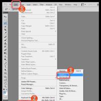 How to change Adobe Reader in Russian How to put Russian in Adobe Reader
 Professional video shooting on smartphone
 Free SAMSUNG KIES drivers in Russian for computer with OS Microsoft Windows
 How to create a channel on YouTube and make money - step by step instructions
 How to completely remove Yandex browser
 Free Update Anti-Virus 360 Total Security do not put vulnerabilities