A device for transmitting data over a radio channel. Packet radio modems. Transmitter output power
This is convenient, increases safety, and allows you to solve a wide variety of problems, including monitoring the progress of production processes and equipment operation.
It is in the latter cases that it is often necessary to install at points significantly remote not only from wired communication networks, but also from the coverage areas of mobile operators.
Today, only video surveillance via a radio channel can offer a huge communication range, while allowing the installation of a transmitter and receiver in difficult terrain.
Features of radio relay communication in video surveillance systems
When people with a technical background think of radio relay communications, they think of bulky, tall towers, powerful amplifiers and enormous energy consumption. Today this is not the case at all.
Radio relay communication systems for solving video surveillance problems are:
- fairly compact and moderately resource-intensive engineering solutions;
- the ability to install translators and receivers on roofs and any supports;
- optimal planning of an engineering solution for a transmission and reception station, with external devices and mixed-type equipment, with separation of functional units with the possibility of their convenient placement.
The organization of radio relay communication has one mandatory condition. The receiver and transmitter must be in direct line of sight.
In addition, when setting up a data transmission channel, careful mutual positioning of the antennas is necessary to obtain a stable signal and maximum broadcast speed.
Equipment used
If we are talking about transmitting a signal from very remote points, it is necessary to carry out quite complex work of installing professional equipment and setting it up.
![]()
Today, for radio relay systems to operate video surveillance wirelessly over long distances, the following are used:
- systems on equipment using PDH transmission technology. The channels formed are considered low and medium speed. At the same time, the cost of the necessary devices is quite affordable, and the requirements for the installation conditions of the transmitter and receiver are not strict;
- systems based on SHD technology allow you to create high-speed channels. For example, using STM-16 level equipment, video streams can be broadcast at speeds of up to 2.5 Gbit/s.
All equipment used for radio relay communications is divided into channel (Half-Duplex) and trunk (Full-Duplex).
At the same time, complex redundancy and redundancy protocols are used in transmission systems to neutralize interference and increase the stability of the radio channel.
However, complex equipment is not always needed by the average user.
Wireless video surveillance ready-made kits - available in several options:
- as a set of devices that allow you to make video surveillance cameras wirelessly from ordinary ones, with data transmission via a radio channel;
- as a ready-made set of equipment, where cameras, and sometimes - are equipped with transmitters, receivers of data via a radio frequency signal.
However, it is worth remembering that a household video surveillance kit via radio channel is a very capricious solution from the point of view of the average user.

It is designed for signal transmission over short distances. For example, this could be a viable option for a car, allowing an owner without technical skills to quickly get CCTV up and running.
However, in a house, especially with many walls and partitions, you will have to think about the placement of cameras, and in some places the signal simply will not be able to get through the obstacles. The same can be said about the coverage of the territory - data transmission from remote points becomes more difficult.
Transmission range
Industrial-grade high-frequency equipment operating at frequencies from 80 to 100 GHz - has a peak transmission range of only a few kilometers.
The distance between communication points depends on the carrier frequency used.

Eg:
- 5-8 GHz translators will provide a range of 50 kilometers or more of reliable signal reception;
- 70-80 GHz - distance drop to 10 km;
- Rarely used 60 GHz stations are considered separately, the signal of which, due to the characteristics of the air, has a strong attenuation coefficient, the total communication range is up to 8 km.
Today, there are many radio relay communication solutions on the market with operating frequencies from 400 MHz to 100 GHz.
So, in fog and rain, powerful low-frequency stations show 35 km of stable reception, and in good weather - up to 80-100 km.
Advantages and disadvantages of radio relay video transmission
Radio relay systems are convenient, reliable, and profitable. The initial investment, despite the fairly high cost of the equipment, pays off handsomely.
The devices offered on the market work reliably and are designed for 30-40 years of operation in harsh conditions with changes in temperature, humidity, ultraviolet radiation and precipitation.
At the same time, it is not difficult to buy a set of equipment whose engineering solution and energy supply requirements will allow you to optimally solve the problem of transmitting a signal over a long distance.
The disadvantages of radio relay communications are noted only by users whose needs are significantly less than the capabilities of the equipment.

For example, we can call the disadvantages:
- The need to build infrastructure (supports, measures, power systems).
- The need for fine tuning of directional equipment.
- High cost for a private person.
As can be seen from the above, none of the disadvantages of radio relay systems can be considered significant when it comes to monitoring the operation of equipment at a remote point or solving other important problems.
Conclusion
Broadcasting a video camera signal over a radio channel is convenient, even if we are not talking about professional equipment.
Today, the market offers convenient solutions for ordinary private users. For example, you can buy a ready-made set of transmitters and receivers, to which ordinary cameras are connected to form a wireless network.
This is convenient in a car, apartment, or private house, as it allows you to avoid complex work, repairs and quickly put video surveillance into operation.
And for companies interested in monitoring remote points, it will not be difficult to choose the best option for professional radio relay communication equipment.
Video: Video surveillance via radio channel, night raid on the roof
In this project we will send and receive digital data using a 433 MHz transmitter and receiver based on Linx modules. If any of the novice radio amateurs, having read about such “terrible” frequencies, immediately got bored, imagining a complex circuit, we hasten to note that there is no simpler circuit, and it is easier to assemble it than, say, an amplifier on the TDA2003. The following pictures show the first part of the project - assembling modules on printed circuit boards and creating RF communications between them.

Linx modules are hybrid chips mounted on small boards designed for surface mounting on the main larger board. The RF part itself is made on a separate printout; the rest of the circuit, for testing and adjustment, can be on any breadboard.

The transmitting part consists of a multivibrator based on a 555 timer. It generates pulses with a period of 1 second, which are transmitted. The transmitter is powered by a single AA battery and uses a MAX756 DC/DC converter that operates in boost mode to convert the 1.5V battery to the 3.3V voltage required by the transmitter. You can keep it simple and immediately power it with the required voltage. The receiver runs on two 1.5 V batteries. It receives pulses sent from the transmitter and this causes the LED to blink. This is our first simple test with the RF channel.


Transmitter and receiver circuit
Equipment with such a circuit ensures stable reception of signals over a distance of 100 meters using a transmitter located in the house.
Communication protocol development
The problem we encountered in the above experiment is that the RF channel is filled with other signals, so the TX module receives something even if the TX module is turned off. Therefore, we need a way to distinguish between our signals and others. We can distinguish between the occurrence of the desired transmission 0 and 1 by sending a burst of tones of varying durations. After numerous experiments, a period of 250 μs was selected for serial data transmission. And the 0 and 1 signals are set to 150 µsec and 200 µsec, respectively. Thus, 1 byte sent by the TX module is preceded by a 400 µsec clock pulse. The figure below shows an oscillogram of the sending of byte 00110100.

PIC program for TX module is here. The program starts after approximately 2 seconds of delay, which is necessary to prevent random data from being sent immediately after turning on the power. The TX module is powered by one AA battery, whose voltage is raised to 3.3 V by the MAX756 chip.


Transmitting part
The receiver is a little more complex. It also powers the MAX756, which converts the 1.5V AA battery to 5V. The 330 ohm resistor drops the voltage to 3V. We can, of course, put the MAX756 in 3.3V mode, but we need 5V to power other devices connected to the receiver module.


Reception part
The receiving program is implemented as a finite state machine with two states. State0 is the starting state. In this state we wait for the pulses to synchronize. First, the PIC comparator indicates transmission. After this, we measure the length of the resulting pulse. If it is significantly lower, it is ignored and the circuit remains in the same state while waiting for the next impulse. The threshold value was established experimentally and is optimal.
As soon as the required clock pulse is received, we move to state1. In this state we get 8 bits and can arrange them into a byte. The transition to this state is only possible if the transmitter sends a synchronizing signal for a long enough time. After measuring the length of the received pulse, we compare it with the threshold. If the pulse is too short, we delete it and return state0 back. Otherwise, we check the pulse duration against another level to distinguish it between 0 and 1. As a result, the resulting bit is stored as a c-bit in the status register and using a left shift we include it in the byte. After receiving 8 bits we return to state0 and the process repeats.
To check that the byte that was sent by the transmitter was actually received, let's make the LED blink the appropriate number of times (4 times in the current setting). After that, we wait about 2 seconds and return back state0 to receive the next byte.
Implementation of ten pulse data coding
We recently discovered a very useful communication protocol that significantly reduces transmitter power consumption. This is a 10-pulse data encoding that uses the intervals between short pulses to encode the 0s and 1s in a byte. This way the transmitter only needs to emit during pulses, which greatly increases battery life. In addition, the receiver can automatically adapt to the data transfer rate. We took as a prototype a program developed for a similar project from a well-known company. The circuits are almost the same as in the previous experiments and use a two-wire interface to the LCD module for debugging. The transmitter sends a text string when a button is pressed and this string is shown on the display on the receiver's side.


TXM and RXM 433 circuits
An important issue is the pulse width that should be used. After much experimentation, we arrived at a value of 100 µs, which corresponds to approximately 5 kBit/s speed at the maximum 10 kBit/s that the transmitter module supports. It turns out that reducing the pulse duration by 2 times leads to less reliable reception. Also, in the 433 MHz range there is a lot of noise in the form of several chaotic pulses at the receiver output. Further reduction in pulse width makes it difficult to distinguish between signal and noise. Thus, we achieved a good balance between receiver sensitivity and noise filtering.


The program for the transmitter begins by pressing a button to wake the transmitter from sleep and send it back to sleep after transmitting data. This significantly reduces the module's power consumption. The current settings provide transmission pulse gaps of 0 and 1810 µsec and 1890 µsec, respectively, while the reference gap is 1350 µsec wide. Thus, the transfer of one byte fluctuates between 7.8 and 15.1 ms, resulting in data transfer rates of approximately 66 and 128 bytes/sec. This is more than enough for most remote controlled devices.

The radio link was tested by placing units in rooms located on different floors of a private house with a distance of 50 meters. Reception of the test signal was stable and error-free.
Single channel remote control
Now we will try to implement 1 control channel in the presence of various interferences. To do this, set the transmitter in the mode of generating symmetrical square pulses, the period of which is regulated by a variable resistor. It is connected to the PIC input of the ADC and the voltage is converted as a delay parameter. The period of the modulating signal can be adjusted in steps of 100 μs starting from 500 μs and up to 255x100+500 = 26 ms, which corresponds to a baseband from 2000 Hz to 30 Hz, respectively.


Transmitter circuit for one command
The receiver allows you to adjust the signal reception sensitivity and tune to a specific modulation frequency. It uses analog output. The voltage at this output is proportional to the signal level. When there is no signal, the constant voltage at this output is about 1.1 V. This voltage is supplied to the non-inverting input of the comparator built into the microcontroller. The inverting input of this comparator is connected to the right (according to the circuit) variable. The voltage at this input should be slightly higher than the non-inverting input and it determines the sensitivity of the system. The code is read at the output of the comparator and the duration of the pulses at its output is measured in units, whose numerical value is set by the left (in the diagram) trimmer. It is connected to the ADC. In this way the entire system can be configured to respond to the modulation frequency and no other frequencies. Hence, it works as a frequency selective filter tuned by a variable resistor.


Receiver circuit for one command
When setting up the system, first selects the modulation frequency in the transmitter. After this, tune the receiver by slowly rotating the variable to the left. Both handles must be in approximately the same position for synchronization. Project files in a shared archive.
Discuss the article DIGITAL DATA TRANSMISSION VIA RADIO CHANNEL
In principle, both AM and FM can be used to transmit television signals over radio channels. In the case of FM, to ensure high noise immunity of transmission, it is necessary that the modulation index m FM be equal to 3...5. In this case, the frequency band ∆f hm occupied by the frequency-modulated signal will be determined by the relation:
∆f hm = 2f B + 2∆f D,
where ∆f D = m hm f B - frequency deviation.
Consequently, to transmit one television signal you will need a radio channel with a frequency band of about 50...70 MHz. Such an expansion of the radio frequency band would lead to a sharp reduction in the total number of transmitted television signals in the frequency range allocated for television broadcasting. In a modern television broadcasting network, only AM is used to transmit television signals over radio channels, despite the lower noise immunity and worse energy performance of radio transmitters compared to FM. The main advantage of AM is that the amplitude-modulated signal occupies a relatively narrow frequency band.
As is known, AM carrier frequency f 0 leads to the formation of two side frequency bands - lower and upper, each of which is equal to the bandwidth of the modulating signal. If the maximum modulating frequency f B = 6 MHz, which corresponds to the upper frequency of the television signal, then the spectrum of modulated frequencies will be equal to f 0 ± f B, i.e. will occupy a band of approximately 12 MHz. Therefore, to be able to transmit a modulated television signal in a standard radio channel having a bandwidth of 8 MHz, the lower sideband of the modulated television signal is partially suppressed, which leads to the elimination of redundancy of information in the amplitude-modulated television signal.
Rice. 8.1. Nominal amplitude-frequency characteristics of radio image and sound transmitters
According to GOST 7845-92, the remainder of the lower side frequency band is 1.25 MHz. In this case, the nominal frequency band of the radio channel allocated for transmitting the television signal directly is 7.625 MHz (Fig. 8.1). Moreover, the attenuation of the frequency components of -1.25 and 6.375 MHz relative to the image carrier frequency is 20 dB. The 0.75 MHz portion of the lower sideband spectrum is transmitted undistorted. The slope of the lower sideband starting at 0.75 MHz below the image carrier frequency is 40 dB/MHz. In this case, the steepness of the slope of the upper side frequency band, next to which the spectrum of the audio signal is located, is estimated to be more than 50 dB/MHz. With this method of transmitting a television signal over a radio channel, the amplitude-frequency response (AFC) of the image path of a television receiver should have the form shown in Fig. 8.2. From Fig. 8.3 it follows that in television receivers the level of the image carrier frequency should be attenuated by 6 dB, i.e. 2 times, and the frequency component of 0.75 MHz of the lower sideband should be attenuated by 20 dB, i.e. 10 times compared to the 1.5 MHz reference frequency level in the upper sideband spectrum. If these conditions are met, after detecting a television radio signal, the total nominal voltage generated at the detector load from the same frequency components of the lower and upper sidebands at any spectral frequency within 0...6 MHz will always be equal to unity if the count is carried out in relative values. In practice, this means that the shape of the resulting frequency response of the television radio signal transmission path from the radio transmitter modulator to the TV detector load will be uniform in a given frequency band of 6 MHz.

Rice. 8.2. Amplitude-frequency characteristic of the radio path of the image of a television receiver

Rice. 8.3. Frequency response of the intermediate frequency amplifier of the image of a television receiver
In each standard radio channel with a width of 8 MHz, in addition to the television signal, the corresponding audio signal is transmitted (see Fig. 8.1). Moreover, the radio audio signal is transmitted using an FM sound carrier frequency, which ensures high noise immunity of the audio path. The maximum frequency deviation is ±50 kHz with the nominal bandwidth occupied by the radio audio signal not exceeding 0.25 MHz. To use a common antenna-feeder system in radio transmitting devices and a common amplification path to amplify the television signal and signal, sound in televisions, it is customary to transmit the sound signal at a carrier frequency close to the image carrier frequency. In reality, the separation of the audio and video carrier frequencies is 6.5 MHz, and the image carrier frequency is less than the audio carrier frequency. Different types of modulation of television and audio radio signals greatly facilitate their separation in televisions. In practice, the power of a radio audio transmitter is 10...20% of the power of a television radio transmitter at the moments of SI transmission. The ratio of the powers of radio image and sound transmitters is selected from the condition of creating identical ranges of action of both transmitters when received by standard television receivers.
Due to the unipolarity of the television signal, two options for the AM radio signal are possible: negative and positive, depending on the polarity of the modulating television signal. In most countries of the world, including our country, negative modulation polarity is adopted, in which the maximum level of the image carrier corresponds to the transmission of the SI level, and the minimum value corresponds to the level of the white television signal. With this modulation polarity compared to positive, impulse noise appears on the television image in most cases in the form of dark dots rather than white, so they are visually less noticeable. The noise immunity of the synchronization path of the television system increases for all types of interference, except pulsed ones, since when transmitting SI, the television radio transmitter emits the maximum, i.e. peak power. With negative polarity of modulation in TVs, it is easier to carry out automatic gain control (AGC), since in the emitted radio signal, regardless of the content of the television image, SI corresponds to the maximum and constant value of the emitted power. In addition, the design of radio transmitters is facilitated, since the average emitted power is much less than the maximum, since white details are more dominant in television images. The main disadvantage of negative modulation polarity is the relatively greater influence of impulse noise on the stability of synchronization in television receivers.
The method of installing the elements of a transmitting television antenna orients the electric and magnetic vectors of the electromagnetic wave, i.e. determines the plane of polarization of electromagnetic radiation. According to GOST 7845-92, it is allowed to use both horizontal (the electric field vector is located in the horizontal plane) and vertical polarization of waves emitted by a television radio transmitter. In free space, horizontal and vertical polarizations of electromagnetic waves do not have any advantages over each other. However, in real conditions, especially in cities with a large number of vertically reflecting objects, such as houses, horizontal polarization provides a lower level of reflected interfering waves, which cause signal fading and interference on the television image in the form of additional contours. In addition, with horizontal polarization, there is less exposure to industrial interference, in particular interference from vehicle ignition systems, which have a vertically polarized component.
Finally, the designs of television antennas with narrow radiation patterns for receiving horizontally polarized electromagnetic waves turn out to be simpler and easier to install on metal supports. Therefore, when organizing television broadcasting in most countries of the world, preference was given to horizontal polarization of electromagnetic radiation.
Modern concepts and the level of technology development make it possible to create a wide variety of complexly branched security television surveillance systems. The main technical problem solved by a video surveillance system is the transmission of a video signal from the source (surveillance object) to the receiver (viewing/recording/storage equipment). In our progressive times, there are many solutions to the issue of video signal transmission, each of which has its own pros and cons, subtleties and composition of the equipment.
The most popular solutions:
1. Transmission of a video signal via cable line. (The basis of any system).
- Coaxial cable (RK, RG ..) (Analog signal, TVI, AHD).
- Twisted pair (UTP, FTP, TPP...) (Analog signal with transceivers, IP digital signal).
2. Signal transmission via radio channel. (The method is not available to everyone by law).
3. Signal transmission via fiber optic line or LAN. (IP digital signal).
| Video signal transmission via coaxial cable (RK, RG). | |
|---|---|
| Pros: | Minuses: |
| Transmits the signal from the video camera to the receiver (video recorder) directly, without the use of additional equipment, because Transmitting and receiving equipment initially provides exactly this method of signal transmission. | The transmission range of a reliable signal is limited to 200-250m, depending on external conditions and the cable products used; Low noise immunity of the cable. In some cases, it is necessary to use isolation transformers and special noise filters. |
| Transmits TVI, AHD signal from the video camera to the receiver (DVR) directly, without the use of additional equipment. The method has been mastered by all manufacturers and is positioned as a way to transfer old systems to a new level in the FullHD format and higher, without replacing the cable line. Noise immunity is higher than that of analog systems. | The transmission range of a reliable signal is limited to 200-250m, depending on external conditions and the cable products used. Typically, TVI and AHD format video cameras only work with their manufacturer's recorders. |
Here are several ways to easily configure the system using video signal transmission via RK and RG cable.
Analogue method (The very beginning of the development of video surveillance)
Performs visual detection of security line violations without video recording (recording).
Analogue method and new transmission formats TVI and AHD.

Performs visual detection with video recording (digitization or signal conversion, archive formation). System capacity 4, 8 or 16 channels. The DVR is installed at a security post or in another room with limited access.
The diagram shows two types of twisted pair transceivers: passive and active. The passive transmitter does not require power, is easy to install, but the signal transmission range from a b/w camera is up to 600 meters, from a color camera up to 400 meters. An active transmitter requires power, most often it is combined with a video signal amplifier, a corrector and an isolator, which significantly increases the video signal transmission range up to 2400 meters and the noise immunity of the system.
You can add (+) to such a solution; UTP cable is cheaper than RK or RG per meter.

This method is not applicable to complex systems and is used in rare cases when it is necessary to identify a repeat offense or theft. And even in such cases, the law is on the side of the offender. But radio signal transmission equipment still exists and is successfully sold.
You can read more about the method of transmitting a video signal over a radio channel in the article Wireless video surveillance.
Below are options for building a video surveillance system using IP cameras.
Transferring a digitized signal from a video camera

This is the simplest way to create video surveillance on IP cameras over a structured cable network. Let's add (+) to the solution for the absence of any interference. The video signal is digitized in a video camera, which eliminates interference from high-frequency cables. Software is installed on the server, the task of which is to communicate with cameras, display video information and save it.
Transfer of digitized signal from recorders

This method is most suitable for transferring an old video surveillance system to a modern level in cases where the server equipment is not satisfied with the recording quality or has broken down. An “encoder” device and a packet shaper are added to analog video cameras.
Transmission of a digitized signal via fiber-optic communication lines

With this solution, any distance is not the limit. It is best used in complex projects where video surveillance is formed from 150-200 cameras. Suitable for any type of objects of varying complexity in architecture and area. Using the solution allows you to build a video surveillance system at a low cost at distributed facilities or at separately located facilities, where it is more convenient to conduct local video recording. For example, ATMs, gas stations, power and transformer substations, payment and information terminals.
Review Project
Description:
Main I idea of the project is to transfer data from one point to another. This transmission can be either wireless over a radio channel or via wire.
In this project, 4 types of data from different types of sensors are transmitted over a radio channel.
The sensors used are temperature sensor, fuel level sensor,
pressure sensor and speed sensor in 1 minute. All these sensors have an analog output in the form of voltage, which is converted into digital data that we can transmit.
Why is it necessary to convert analog signals to digital?
Suppose that we have converted analog signals into digital data. What's next? Since we must transmit four different types of data over one channel, we need to combine them. Analogue signals cannot be combined, for digital signals we can use a digital switch, which will combine the data into one stream one after another.
Note: data transfer rate is from 12 to 15 cycles per minute.
Data transfer:

The block diagram shows an example of data transmission using
any signal modulation.

After receiving data from the receiver and demodulating it, we will get real data,
which were transmitted by the transmitter and we can easily show them.
Functional block diagram:

Digital part diagram:

Fig.1 (section A)

Fig.2 (Section B - radio frequency transmitter)
Description of the scheme:
In section"A" shows a digital receiver of signals from 4 sensors. This uses analog
switch IC M4066, which works as well as digital.
It has four I/O devices and separate pins to control the transfer of analog signals through the switch. The switch control lines are connected to the microcontroller pins (ports 2.1 - 2.4).
Because these are all analogue signals, so we have to convert them into digital form
via an analog-to-digital converter. For this purpose we used IC ADC0804.
This is an 8-bit ADC and at its output we have the digital equivalent of an analog signal with
range of values from 0 to 255. From the ADC, 8-bit data enters the microprocessor
(ports 1.0 - 1.7). By multiplexing 4 analog signals in series
are converted into digital form and transmitted as a single data stream to the transmitter modulator.


Fig.3 (commentary on the digital circuit)
To To transmit a signal over a distance, we must modulate it in the transmitter. It is good when the modulator circuit is combined with the transmitter. This scheme uses frequency modulation due to its simplicity and long signal transmission range, which can be about 2 km. For example, the FM broadcast band is wide enough for possible data transmission. This transmitter transmits a signal at a frequency of 98 MHz. But the transmitter signal will not exactly match the modulating digital signal (square wave shape). Here we say that the signal is only similar in shape to a square wave. An exact view of the transmitter waveform can be seen on an oscilloscope.
Radio frequency The transmitter in this project is assembled according to the simplest circuit (Fig. 2). It is an LC exciter on one transistor combined with FM modulator circuits. Transmitter output power is about 0.8 W. The frequency of the self-oscillator is 98 MHz. The receiver is a regular broadcast receiver with a suitable VHF band. The range of reliable reception and demodulation of digital data is no more than 2 kilometers. And using this equipment cannot be improved.
PS:
This article is provided only as an example of the use of technology. It does not specify the types of effective modulators/demodulators and uses a technically imperfect radio channel for data transmission.
 We play Android games on the computer How to play PC games on Android
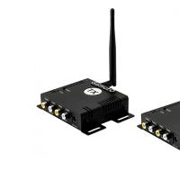 Radio data transmission device
 Beautiful mouse cursor, how to install it on your computer Large cursors for windows 7
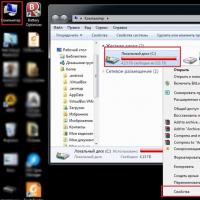 How to make your computer stop slowing down After activating Windows 7, your computer slows down
 How to take a screenshot without the Power button and the Home button on Android?
 Qiwi wallet - reserve account
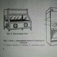 Methods of laboratory tests for identifying viruses and features of deciphering research results