Map of Yota base stations. Map of MTS coverage area Map of coordinates of MTS base stations
One of the first questions that arises when you are connecting to the mobile Internet is the question of where to locate the base station of your chosen operator so that you can point your antenna towards it. It is advisable to find out the exact coordinates of the tower and the terrain before it in order to understand whether it makes sense to use the tower to receive the signal. Services and various Android applications do not provide exact coordinates of the BS, because based on measurements and their mathematical processing. The error can reach several kilometers.
Often, tower coordinates can be determined by studying operator coverage maps, terrain, Google and Yandex maps, as well as the opportunities they provide to view photographs and panoramas of the area being studied. It must be said that the BS cannot always be found on the map. There can be many reasons for this - the maps are outdated, the BS is located on the roof of the building and is simply not visible on the map, the tower is small, etc.
BS parameters are unknown. Kostroma region
Given: coordinates 57.564243, 41.08345, Kuzminka village in the Kostroma region.
The task is to determine the exact coordinates of the BS to which you can connect to receive a 3G signal. We will consider the search for BS step by step.
Step 1. Analysis of coverage maps.
Let's use the well-known service yota-faq.ru/yota-zone-map/, which presents the coverage areas of four operators, except Beeline. I will note here that the Beeline coverage presented on their website is almost impossible to use - as a rule, it shows continuous coverage that does not take into account the terrain. The coverage areas of Megafon and MTS look the most interesting from a connection point of view. You can see this for yourself by opening the service, inserting coordinates into the search bar and switching operators.
Megafon coverage area:
MTS coverage area:

From the analysis of Megafon's coverage area, we see that 3G BS are most likely located in the directions Krasnoye, Sukhonogovo, Lapino (at this scale the Lapino map is not visible, this is the southwest, approximately where the P-600 mark is).
The MTS coverage area is more interesting. Here we also consider the direction to Sukhonogovo and Krasnoe. But Red is a more interesting option, because... there is 4G coverage there. The distance to Krasny is about 10 km, if MTS distributes 4G at a frequency of 1800 MHz, then there is every chance of establishing communication with one of the MTS BSs located in this locality.
Step 2. Study of the terrain.
The terrain up to Krasny is difficult, but quite passable. To assess the terrain, we will use the service https://airlink.ubnt.com. If this is your first time on this site, you will first need to go through a free registration procedure. Having opened the service, scroll the slider down to the end and enter the initial data in the lower right corner, as shown in the following figure.
I usually first enter the same coordinates in both windows, and then start moving the purple mark to the points of interest to me, where the BS could presumably be located. In this case, the top right corner of the screen displays the terrain, the line of sight and the approximate size of the Fresnel zone.
For our coordinates we have:

Checking the terrain in other “suspicious” directions showed that the terrain there is much worse. Thus, we decided on the direction and at the same time chose the operator - MTS.
Step 3. Clarifying our choice using the “Communication Quality” service
The service opens at the following address https://geo.minsvyaz.ru. In the search line, set the name of the village of Kuzminka, switch the view from 4 windows to single-window mode, scale the map to a convenient size and get for the MTS operator:

We see that our choice is correct, because according to the measurement database of users of this service, Krasnoye actually has good 4G coverage from MTS.
Let's zoom in on this map and see that the most likely location of the tower (or towers) is Sovetskaya and Okruzhnaya streets.

Step 4. Study the area using Google and Yandex maps.
These maps have a useful tool for studying the area - panoramas and photographs of the area. Google maps have much more panoramas of various areas than Yandex, so you have to use Google more often when looking at panoramas. On the other hand, Yandex has more photos taken in different places, in addition, Yandex maps for Russia are usually more relevant. In this regard, you have to use both services. Google maps and services are used here.
So, we found out that we need to consider two streets in Krasnoye in search of BS. Launch Google maps, enter the approximate coordinates of the street. Sovetskaya (or street name) and we get:

Here the street view mode is turned on, the street we need is highlighted in blue on the map. You can get a panorama of the street by clicking the mouse anywhere on the blue line. Moving in this way along the street to the north, at the post office building we find the first BS:

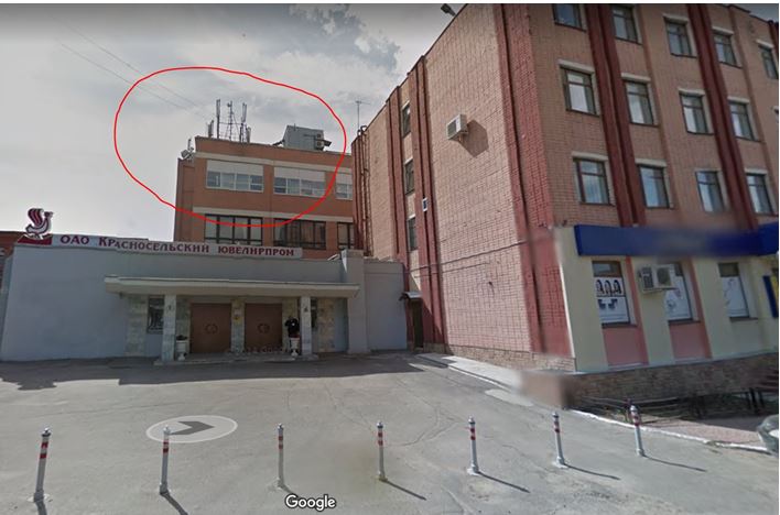
And finally, not far from the intersection of Sovetskaya and Okruzhnaya streets, a third tower is discovered, the highest of those found:
We return to the map and find the shadow of this tower in the place where the photo points:

We mark this place on the map with the mouse and get the exact coordinates of the BS:

Let us summarize some of the results of our research. Using information obtained from coverage area analysis, user measurements of signal strength in the area of interest, and study of the area through photographs and panoramas, we were able to find three base stations and their exact coordinates in a city we had never been to. The question of which operator owns the found BS remains open, because the answer to this requires additional research. The easiest way is to drive along the route and measure the BS parameters using some Android application that displays MNC, MCC and signal strength. Some of these applications are presented here.
The parameters of the BS are known. Suburb of Penza
As is known, a number of Android applications, as well as a HiLink modem interface and an MDMA program, can provide BS parameters, with the help of which well-known services and applications can provide approximate BS coordinates, which makes it easier to find specific BS coordinates on maps. Let's look at a specific example from the forum, the example is based on
Distance to the tower is approximately 4800 meters:

As can be seen from our research, the error in determining the BS coordinates obtained using the xinit.ru/bs service is very significant - almost 2 km. Such errors are typical for all services based on user measurement databases, but there are no other services available.
Conclusion
The presented technique, based on the use of widely available cartographic tools, does not always, but quite often allows one to find the exact coordinates of the BS. Significant assistance in determining whether a BS belongs to a particular operator is provided by services that provide information on the parameters of the BS and its approximate coordinates.
In order to choose the optimal kit for reliable Internet operation, you need to know the answers to several questions.
- Where and at what distance is the nearest base station with Internet access?
- Is there a direct line of sight to the base station from the location where the antenna is supposed to be installed?
- How long is the RF reduction cable needed to connect the antenna?
There are two options to answer the first question.
First option:
The easiest way is to use coverage maps that cellular operators publish on their websites.
Below is a list of links to coverage maps of major cell phone carriers.
Let’s set ourselves the task of determining the possibility of receiving 3G Internet in the village of Nagishi, Ryazan region. Based on the coverage map of the MTS operator, we determine that the nearest base station is located in the village of Gorlovo, Ryazan region.
We find a more or less exact location of the base station. As a rule, the radiation pattern of the base station antennas is similar to a trefoil because the base uses three sector antennas with a radiation pattern of 120°, and the base will be located in the center of this figure.
Next, using the Yandex map, we find the distances between the client and the base station. This is necessary so as not to do extra work because if the distance is more than 30 km, then most likely it will not be possible to establish a 3G connection

Using the "Get Information" tool, we determine the coordinates of the 3G base station and the location of the proposed antenna installation.
We got the following coordinates:
Base 53°49′37.35″N 39°2′30.3″E
Client 53°50′20.41″N 38°55′7.82″E
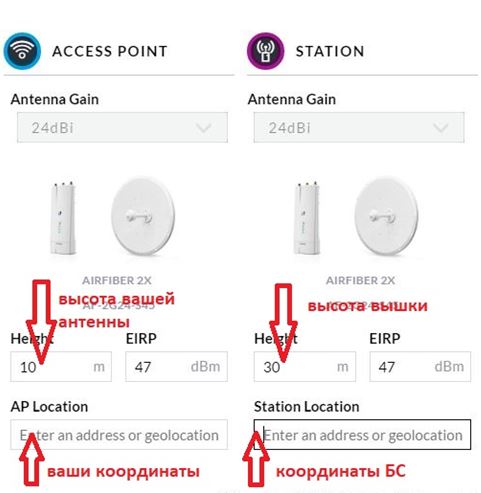
The first service is very simple and straightforward, you just need to enter the coordinates of the base and the client indicate the height from the surface of the earth for the base this is usually from 50 to 120m, for the client 10-15m.
There is one limitation that this service will not be able to build a route if the coordinates of the place are more than 60° N or 60° S. That is, it will no longer be possible to calculate the route in the Arkhangelsk area.
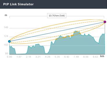
This is what happened in our case.


According to the route graph, it is clear that nothing prevents you from obtaining reliable reception at the antenna installation site, even if the base height is less (50m), direct visibility between the antennas will still be ensured.
When entering a resource, we immediately go to the tab Tower


We delete the lists of base stations by clicking on the “cross” to the right of the table and fill in the data of our database to save, click Refresh
Go to the tab Map
We reduce the size of the map and move the “cross” to the location of the receiving antenna, guided by the names on the map and the coordinates at the bottom of the map.


Clicking on the tab Profiles You can see the route profile. As you can see in the right figure, the route is open and can provide reliable 3G reception.
Scroll down the page to the heading "System Performance"
We will proceed from the fact that in order to obtain a signal level on the receiving side of at least -85 dBm, and a gain margin “for bad weather” of at least 10 dB.
![]()
We fill in the empty fields based on the fact that the receiving antenna has a gain of 14 dB, the transmitting one is 12 dB, the power of the base transmitter is 3 W, the loss in the base reduction cable is 2 dB, in the receiving antenna reduction cable is 5 dB. Click calculate and get the result above. Based on the calculated data, it turns out that the gain margin is 24 dB, that is, it will work in any weather. The signal level on the receiving side will be about -64 dB, which will allow you to have confident, stable Internet reception at the highest possible speed.
Second option:
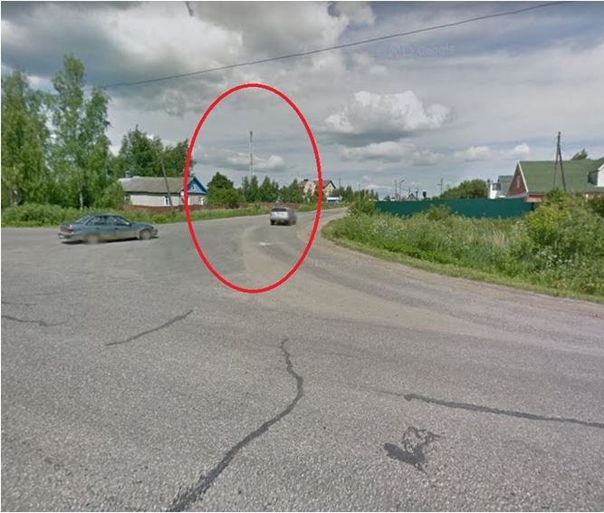
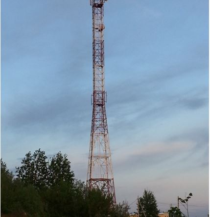
In order to find out the location of the base station, you need to take a phone with 3G support (nowadays this is no longer uncommon), and, guided by the signal strength indicator on the phone, move towards strengthening the signal until a structure similar to those shown below appears in your field of view:


Having marked the location of the station using maps http://maps.yandex.ru, we determine the distance to the installation site and coordinates.
The antenna should be installed in an open space, as high as possible from the ground surface and oriented towards the signal source. It is better to mount the antenna on a separate, grounded mast or wall of the house facing the base station. The antenna in the direction of the base station should not be blocked by vegetation and tall objects, even at a considerable distance and within a radius of about 8 meters from the axis of the path - this will greatly weaken the ability to receive 3G Internet. Remember that for the antenna to work, you need direct visibility to the base station! Also, you cannot install the antenna under the roof of the house, even from non-metallic parts (slate, rubber, roofing felt, etc.). Also, you should not install the antenna near the chimney; excessive uneven heating will damage the antenna.
Today, the cell phone has become an important part of our lives. With the help of it we correspond, call each other and use the mobile Internet. But even now, when cellular operators do everything to improve communication, there are failures, and sometimes the connection disappears or is completely absent. Not everyone knows how cellular communications work and what determines its quality. To cover the territory and high quality of cellular communications, operator companies are increasingly building (installing) base stations. A base station map will help you stay connected. Each operator has a wide network of 3G (third generation) and 4G LTE (fourth generation) base stations. If you have not yet decided on the choice of operator or want to switch to another, you may be interested in the map of cellular base stations of the operator you need, which will show in detail the coverage area. The range of one station depends on the location and frequency range. 3G stations in megacities reach 500m, in open areas - up to 35km. 4G LTE stations - the radius can be different, optimally it is about 5 km, but if necessary it can be up to 30 km or even 100 km (if the antenna is raised sufficiently).
Mobile operators have learned to combine low and high frequencies. For areas where a small number of subscribers live, but they occupy a large area, networks operating in low bands are ideal. And in large and densely populated cities, high-band networks are being built. Dual-band LTE networks are the future of mobile communications.
You can view a map and find out the coordinates of base stations of cellular operators, as well as understand the coverage areas of cellular operators depending on the region on various websites. Examples of such sites include the following resources:
- http://bsmaps.ru/maps.php - coverage areas of Megafon, MTS, Tele2 in the central federal district;
- http://tolyatti.beeline.ru/customers/beeline-on-map/ - Beeline coverage areas
- http://www.mts.ru/mobil_inet_and_tv/help/mts/coverage/ - MTS coverage area
The quality of cellular communications varies among operator companies. A people’s project, “Communication Quality”, has been launched on the State Services website (creating a cellular communication quality map using the “Communication Quality” mobile application). https://www.gosuslugi.ru/555666/1/
On the Angry Citizen project, you can complain about poor communication quality.
If the coverage is unsatisfactory and there are areas that are not covered ("white spots"), then the connection is unstable and may fail. Our resource was created to solve these problems.
Here you can see the layout of base stations on the interactive
Detecting communication towers is not a criminal activity, but a fairly common task in remote regions and villages where the quality of coverage leaves much to be desired. How can you understand why this post gives better results than that wicket? The following tools and websites can help you navigate.
Of the English-language services, perhaps the best is opensignal.com, where you can select the operator and the required location. The map does not show towers, but does show coverage areas. Among the Russians, I can recommend netmonitor.ru - its database contains a lot of information about operator towers.
Some Android applications are also interesting. For example, OpenSignal displays a map of cell towers and Wi-Fi points (locations with poor connections are also marked on the map), has a built-in compass and a speed checker.
Another interesting utility is Netmonitor. It can monitor GSM and CDMA networks, shows information about signal strength, contains a database of cell towers, supports devices with multiple SIM cards, and can also keep a log in CLF or KLM format.

Please note that Netmonitor has limitations when running on devices from some manufacturers. On Motorola, LG, Samsung, Acer and Huawei smartphones, the list of neighbors may be empty, and on Samsung devices, the signal strength may also not be displayed.
I also recommend the GSM Signal Monitoring application, which allows you to work with GSM, UMTS and LTE networks. It displays the change in signal level on a graph and shows neighboring cells (only in GSM networks). There is a data transfer rate monitor and the ability to track connection status, connection standard, cell and current zone identifiers (LAC/RNC/TAC) and received signal strength level (RSSI, as well as RSRP for LTE).

Knowing the data of the base station, you can access it through the website xinit.ru and obtain information about its location. In large cities, it doesn’t hurt to try to find popular maps with the location of the towers, but you should understand that the towers belong to different operators. Plus, base stations are placed not only on poles, but also on the roofs of houses.
Published 04/22/2015 by John
Cellidfinder is a simple and convenient service for finding the location of GSM mobile communication base stations and plotting them on a map. The article provides detailed instructions for finding the location of GSM base stations using this service.
What data is needed to localize the BS?
In order to find the coordinates of the base station sector, you need to know 4 parameters:
- MCC (Mobile Country Code) is a code that determines the country in which the mobile operator is located. For example, for Russia it is 250, the USA - 310, Hungary - 216, China - 460, Ukraine - 255, Belarus - 257.
- MNC (Mobile Network Code) is a code assigned to a mobile operator. Unique for each operator in a particular country. A detailed table of MCC and MNC codes for operators worldwide is available.
- LAC (Location Area Code) - local area code. In a nutshell, LAC is an association of a number of base stations that are served by one base station controller (BSC). This parameter can be presented in either decimal or hexadecimal format.
- CellID (CID) - “cell identifier”. The same sector of the base station. This parameter can also be presented in decimal and hexadecimal format.
Where can I get this data?
The data is taken from the netmonitor. Netmonitor is a special application for mobile phones or other devices that allows you to find out the engineering parameters of a mobile network. There are a huge number of netmonitors for various devices on the Internet. Finding the right one is not a problem. In addition, many modern GPS trackers, in conditions of poor satellite reception, can send to the owner not coordinates, but parameters of the base station (MCS, MNC, LAC, Cellid) to which they cling. Cellidfinder will help you quickly translate these parameters into the approximate location of the BS.
Where do the coordinates of the base station come from?
The search for coordinates of base stations is carried out in the Google and Yandex databases, which provide such an opportunity. It should be noted that as a result of the search we do not get the exact location of the tower, but an approximate one. This is the location in which the largest number of subscribers were registered and transmitted information about their location to Google and Yandex servers. The most accurate location by LAC and CID is determined by using the averaging function, which calculates the coordinates of all sectors (CellID) of one base station, and then calculates the average value.
How to work with CellIDfinder?
In order to start working with the CellIdfinder base station location search service, you need to install any netmonitor on your smartphone. Here is one of the good options. We turn on the downloaded application and look at the necessary parameters.
In this case, in the netmonitor window we saw:
MCC = 257 (Belarus)
MNC = 02 (MTS)
LAC = 16
CID = 2224
We enter these parameters into the search form on . Because LAC and CID can be issued by the netmonitor in both decimal and hexadecimal form; the search form has auto-complete for LAC and CID in the second form. Select “Google Data”, “Yandex Data” and, if high accuracy is needed, “Averaging”. Click the "Find BS" button.

As a result, we obtained the coordinates for this sector of the base station. Moreover, the coordinates in the Google and Yandex databases practically coincided, which means we can assume that the BS are built on the map quite accurately.
Despite the rapid development of modern technologies, high-quality mobile communications are not available everywhere. That is why subscribers need to know the MTS coverage area.
This concept indicates the territory where SIM card owners are able to receive a high-quality signal and use cellular communications. This area depends on the location of towers and base stations. But users should take into account that the quality of reception is affected by:
- relief of the surrounding area;
- weather (in thunderstorms and squally winds the quality decreases);
- the technical condition of the phone and the ability of the phone to support modern technologies, including 4g.
Users should take each of these factors into account, but remember that it is the radio towers that have the main influence on network connectivity.
As such, a map of radio towers and stations is not of great importance to subscribers. This is due to the fact that the coverage radius of each tower depends on the frequencies used by the operator and its location:
- points using the 450 MHz frequency are capable of covering up to 20 km;
- coverage of 800 MHz points – up to 13.5 km;
- 1800 MHz – up to 7 km;
- 2600 – 3,2.
It is important to emphasize that most Russian operators, including MTS, use universal radio towers that operate in several bands at once. This allows you to avoid difficulties with connecting to 3g and 4g and provide clients with reliable, stable communications.
Another factor influencing the location of towers is the number of subscribers in a populated area. The larger the city and the greater the number of connected users, the more often the radio towers are located. In this case, their number directly affects the operator’s ability to maintain the network.
MTS 3g and 4g network coverage map
Currently, the MTS coverage map covers almost the entire territory of Russia. Cellular operator is available in every locality. However, it has not yet been possible to get rid of the white spots. And the higher the quality of communication, the more places where users cannot use it.

The best situation with coverage is in Moscow, the Moscow region, St. Petersburg and the Krasnodar Territory. There will be no difficulties for residents of regional, regional, republican centers and large cities.
To get more detailed information, you should visit the company’s official website and open the corresponding section. The link to it is on the start page. At the same time, the operator offers a separate card for each region of the country.
And again, some general educational material. This time we will talk about base stations. Let's look at various technical aspects of their placement, design and range, and also look inside the antenna unit itself.
Base stations. General information
This is what cellular antennas look like installed on the roofs of buildings. These antennas are an element of a base station (BS), and specifically a device for receiving and transmitting a radio signal from one subscriber to another, and then through an amplifier to the base station controller and other devices. Being the most visible part of the BS, they are installed on antenna masts, roofs of residential and industrial buildings, and even chimneys. Today you can find more exotic options for their installation; in Russia they are already installed on lighting poles, and in Egypt they are even “disguised” as palm trees.

The connection of the base station to the telecom operator’s network can be done via radio relay communication, so next to the “rectangular” antennas of the BS units you can see a radio relay dish:

With the transition to more modern standards of the fourth and fifth generations, to meet their requirements, stations will need to be connected exclusively via fiber optics. In modern BS designs, optical fiber becomes an integral medium for transmitting information even between nodes and blocks of the BS itself. For example, the figure below shows the design of a modern base station, where fiber optic cable is used to transmit data from the RRU (remote controlled units) antenna to the base station itself (shown in orange).

The base station equipment is located in non-residential premises of the building, or installed in specialized containers (attached to walls or poles), because modern equipment is quite compact and can easily fit into the system unit of a server computer. Often the radio module is installed next to the antenna unit, this helps reduce losses and dissipation of power transmitted to the antenna. This is what the three installed radio modules of the Flexi Multiradio base station equipment look like, mounted directly on the mast:

Base station service area
To begin with, it should be noted that there are different types of base stations: macro, micro, pico and femtocells. Let's start small. And, in short, a femtocell is not a base station. It is rather an Access Point. This equipment is initially aimed at a home or office user and the owner of such equipment is a private or legal entity. a person other than the operator. The main difference between such equipment is that it has a fully automatic configuration, from assessing radio parameters to connecting to the operator’s network. Femtocell has the dimensions of a home router:

A picocell is a low-power BS owned by an operator and using IP/Ethernet as a transport network. Usually installed in places where there is a possible local concentration of users. The device is comparable in size to a small laptop:

A microcell is an approximate version of the implementation of a base station in a compact form, very common in operator networks. It is distinguished from a “large” base station by a reduced capacity supported by the subscriber and lower radiating power. Weight, as a rule, is up to 50 kg and radio coverage radius is up to 5 km. This solution is used where high network capacities and power are not needed, or where it is not possible to install a large station:

And finally, a macro cell is a standard base station on the basis of which mobile networks are built. It is characterized by powers of the order of 50 W and a coverage radius of up to 100 km (in the limit). The weight of the stand can reach 300 kg.
The coverage area of each BS depends on the height of the antenna section, the terrain and the number of obstacles on the way to the subscriber. When installing a base station, the coverage radius is not always at the forefront. As the subscriber base grows, the maximum throughput of the BS may not be enough, in which case the message “network busy” appears on the phone screen. Then, over time, the operator in this area can deliberately reduce the range of the base station and install several additional stations in areas of greatest load.
When you need to increase network capacity and reduce the load on individual base stations, then microcells come to the rescue. In a megacity, the radio coverage area of one microcell can be only 500 meters.
In a city environment, oddly enough, there are places where the operator needs to locally connect an area with a lot of traffic (metro station areas, large central streets, etc.). In this case, low-power microcells and picocells are used, the antenna units of which can be placed on low buildings and on street lighting poles. When the question arises of organizing high-quality radio coverage inside closed buildings (shopping and business centers, hypermarkets, etc.), then picocell base stations come to the rescue.
Outside cities, the operating range of individual base stations comes to the fore, so the installation of each base station away from the city is becoming an increasingly expensive enterprise due to the need to build power lines, roads and towers in difficult climatic and technological conditions. To increase the coverage area, it is advisable to install the BS on higher masts, use directional sector emitters, and lower frequencies that are less susceptible to attenuation.

So, for example, in the 1800 MHz band, the range of the BS does not exceed 6-7 kilometers, and in the case of using the 900 MHz band, the coverage area can reach 32 kilometers, all other things being equal.
Base station antennas. Let's take a look inside
In cellular communications, sector panel antennas are most often used, which have a radiation pattern with a width of 120, 90, 60 and 30 degrees. Accordingly, to organize communication in all directions (from 0 to 360), 3 (pattern width 120 degrees) or 6 (pattern width 60 degrees) antenna units may be required. An example of organizing uniform coverage in all directions is shown in the figure below:

And below is a view of typical radiation patterns on a logarithmic scale.

Most base station antennas are broadband, allowing operation in one, two or three frequency bands. Starting with UMTS networks, unlike GSM, base station antennas are able to change the radio coverage area depending on the load on the network. One of the most effective methods of controlling radiated power is to control the angle of the antenna, in this way the irradiation area of the radiation pattern changes.
Antennas can have a fixed tilt angle, or can be remotely adjusted using special software located in the BS control unit and built-in phase shifters. There are also solutions that allow you to change the service area from the general data network management system. In this way, it is possible to regulate the service area of the entire sector of the base station.
Base station antennas use both mechanical and electrical pattern control. Mechanical control is easier to implement, but often leads to distortion of the radiation pattern due to the influence of structural parts. Most BS antennas have an electrical tilt angle adjustment system.
A modern antenna unit is a group of radiating elements of an antenna array. The distance between the array elements is selected in such a way as to obtain the lowest level of side lobes of the radiation pattern. The most common panel antenna lengths are from 0.7 to 2.6 meters (for multi-band antenna panels). The gain varies from 12 to 20 dBi.
The figure below (left) shows the design of one of the most common (but already outdated) antenna panels.

Here, the antenna panel emitters are half-wave symmetrical electric vibrators above the conductive screen, located at an angle of 45 degrees. This design allows you to create a diagram with a main lobe width of 65 or 90 degrees. In this design, dual- and even tri-band antenna units are produced (though quite large). For example, a tri-band antenna panel of this design (900, 1800, 2100 MHz) differs from a single-band one, being approximately twice as large in size and weight, which, of course, makes it difficult to maintain.
An alternative manufacturing technology for such antennas involves making strip antenna radiators (square-shaped metal plates), in the figure above on the right.
And here is another option, when half-wave slot magnetic vibrators are used as a radiator. The power line, slots and screen are made on one printed circuit board with double-sided foil fiberglass:

Taking into account the modern realities of the development of wireless technologies, base stations must support 2G, 3G and LTE networks. And if the control units of base stations of networks of different generations can be placed in one switching cabinet without increasing the overall size, then significant difficulties arise with the antenna part.
For example, in multi-band antenna panels the number of coaxial connecting lines reaches 100 meters! Such a significant cable length and the number of soldered connections inevitably leads to line losses and a decrease in gain:

In order to reduce electrical losses and reduce solder points, microstrip lines are often made; this makes it possible to create dipoles and the power supply system for the entire antenna using a single printed technology. This technology is easy to manufacture and ensures high repeatability of antenna characteristics during serial production.
Multiband antennas
With the development of third and fourth generation communication networks, modernization of the antenna part of both base stations and cell phones is required. Antennas must operate in new additional bands exceeding 2.2 GHz. Moreover, work in two and even three ranges must be carried out simultaneously. As a result, the antenna part includes rather complex electromechanical circuits, which must ensure proper functioning in difficult climatic conditions.
As an example, consider the design of the emitters of a dual-band antenna of a Powerwave cellular communication base station operating in the ranges 824-960 MHz and 1710-2170 MHz. Its appearance is shown in the figure below:

This dual-band irradiator consists of two metal plates. The larger one operates in the lower 900 MHz range; above it is a plate with a smaller slot emitter. Both antennas are excited by slot emitters and thus have a single power line.
If dipole antennas are used as emitters, then it is necessary to install a separate dipole for each wave range. Individual dipoles must have their own power line, which, of course, reduces the overall reliability of the system and increases power consumption. An example of such a design is the Kathrein antenna for the same frequency range as discussed above:

Thus, the dipoles for the lower frequency range are, as it were, inside the dipoles of the upper range.
To implement three- (or more) band operating modes, printed multilayer antennas have the greatest technological effectiveness. In such antennas, each new layer operates in a rather narrow frequency range. This “multi-story” design is made of printed antennas with individual emitters, each antenna is tuned to individual frequencies in the operating range. The design is illustrated in the figure below:
As in any other multi-element antennas, in this design there is interaction between elements operating in different frequency ranges. Of course, this interaction affects the directivity and matching of the antennas, but this interaction can be eliminated by methods used in phased array antennas (phased array antennas). For example, one of the most effective methods is to change the design parameters of the elements by displacing the exciting device, as well as changing the dimensions of the feed itself and the thickness of the dielectric separating layer.
An important point is that all modern wireless technologies are broadband, and the operating frequency bandwidth is at least 0.2 GHz. Antennas based on complementary structures, a typical example of which are “bow-tie” antennas, have a wide operating frequency band. Coordination of such an antenna with the transmission line is carried out by selecting the excitation point and optimizing its configuration. To expand the operating frequency band, by agreement, the “butterfly” is supplemented with a capacitive input impedance.
Modeling and calculation of such antennas are carried out in specialized CAD software packages. Modern programs allow you to simulate an antenna in a translucent housing in the presence of the influence of various structural elements of the antenna system and thereby allow you to perform a fairly accurate engineering analysis.
The design of a multi-band antenna is carried out in stages. First, a microstrip printed antenna with a wide bandwidth is calculated and designed for each operating frequency range separately. Next, printed antennas of different ranges are combined (overlapping each other) and their joint operation is examined, eliminating, if possible, the causes of mutual influence.

A broadband butterfly antenna can be successfully used as the basis for a tri-band printed antenna. The figure below shows four different configuration options.

The above antenna designs differ in the shape of the reactive element, which is used to expand the operating frequency band by agreement. Each layer of such a tri-band antenna is a microstrip emitter of given geometric dimensions. The lower the frequencies, the larger the relative size of such an emitter. Each layer of the PCB is separated from the other by a dielectric. The above design can operate in the GSM 1900 band (1850-1990 MHz) - accepts the bottom layer; WiMAX (2.5 - 2.69 GHz) - receives the middle layer; WiMAX (3.3 - 3.5 GHz) - receives the upper layer. This design of the antenna system will make it possible to receive and transmit radio signals without the use of additional active equipment, thereby not increasing the overall dimensions of the antenna unit.
And in conclusion, a little about the dangers of BS
Sometimes, base stations of cellular operators are installed directly on the roofs of residential buildings, which actually demoralizes some of their inhabitants. Apartment owners stop having cats, and gray hair begins to appear faster on grandma's head. Meanwhile, the residents of this house receive almost no electromagnetic field from the installed base station, because the base station does not radiate “downward.” And, by the way, SaNPiN standards for electromagnetic radiation in the Russian Federation are an order of magnitude lower than in “developed” Western countries, and therefore base stations within the city never operate at full capacity. Thus, there is no harm from BS, unless you sunbathe on the roof a couple of meters from them. Often, a dozen access points installed in residents' apartments, as well as microwave ovens and cell phones (pressed to the head) have a much greater impact on you than a base station installed 100 meters outside the building.
 Beautiful mouse cursor, how to install it on your computer Large cursors for windows 7
 Setting up mail on iPhone and iPad
 Free online image to PDF converter
 Qiwi wallet - reserve account
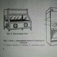 Methods of laboratory tests for identifying viruses and features of deciphering research results
 Which forum is better vBulletin or PunBB
 How to create a second VKontakte page?