AutoCAD how to find out units of measurement. Setting up an AutoCAD drawing. How to find area in AutoCAD in the standard way
Open the AutoCAD program. This program is either present as an icon on your desktop, or you can find it in the Start menu in the lower left corner of the screen.
Go to Model Space. There are two types of space in AutoCAD: Model Space and Paper Space. Your drawing should be done in Model Space, and the dimensions you add later should be in Paper Space. To switch between model and paper spaces, look at the tabs at the bottom of the screen. One tab is called 'Model Space' and the other tabs are called either 'Sheet' or 'Schematic'. The 'Sheet' or 'Scheme' tabs represent the paper space. If you are currently in Model Space mode, the screen background should be black. If you are in Paper Space mode, the background should be white.
Set the units of measurement. Engineers set different units of measurement: feet, meters, etc. To ensure accuracy and avoid confusion, it is important that the drawing is made in appropriate units. To set the units of measurement, type 'UN' on the keyboard and press the 'ENTER' key. A dialog box should appear that allows you to specify the units and precision. Type options for units of measurement are: Decimal, Scientific, Engineering, Architectural, Fractional. The 'Accuracy' section will allow you to select the number of decimal places for your dimensions. If you are doing a project for your teacher, he should have information regarding the specification of units of measurement.
Select the toolbars that will be used to create your drawing. To do this, hover your mouse over the empty space at the top of the screen next to the toolbars. Right-click and select "AutoCAD". A long list should appear with different toolbars containing different commands. The most popular toolbars used for 2D drawings in AutoCAD are Draw, Editor, and Object Properties. Select these panels and they should appear on the screen. Move them to the side to create space for your drawing. The Draw panel contains basic drawing tools. The Editor panel contains editing tools. The Object Properties panel contains style and color controls
Turn on Snap mode."Snapping", which refers to the snapping of objects, is the most important property when creating a drawing. It allows you to see where the midpoint and endpoint of a line is, the tangent of a circle, and other useful information. To enable Snap mode, press F3 on your keyboard. To make sure snapping mode is enabled, right-click on the icon labeled ‘Snapping’ in the lower left corner of the screen. A dialog box should appear on the screen. Click on the ‘Select All’ button, thereby enabling all binding options.
After you have configured the program and saved, if necessary, the settings to a file, you need to proceed to setting up the drawing. All settings and manipulations made on the drawing will be saved along with it. Moreover, all settings will be available for editing every time the drawing is opened and will relate specifically to this specific drawing. The main drawing settings are: limits, line types, dimension and text styles.Basically, drawing settings in programs like AutoCAD are performed interactively or in the form of a user dialogue with the program. All this activity is carried out with the help of teams. In turn, commands are entered using the menu, on the toolbar, or by entering the name of the command in the command line. We will not consider entering commands using the menu and toolbar. Entering commands directly into the command line requires knowledge of their names.
About limits.
There are two spaces in AutoCAD - model and paper spaces. Basically, a drawing is created in model space, in which the work area is infinite. For orientation in an area, limits are used that limit an area of specified dimensions.
The limits are set by the coordinates of the lower left and upper right corners of the rectangular area. To set limits you need to select the command Format\Drawing limits(Format\Drawing).
This command calls the AutoCAD LIMITS command, which can be accessed by typing _limits at the command line.
Below the command AutoCAD will display a comment line Resetting Model Space Limits and the dialog line Lower left corner or (ON/OFF) “0.0000, 0.0000”.
Purpose of units of measurement
AutoCAD provides linear and angular units of measurement. What does it mean? This means, for example, that when you set the coordinates of the upper right corner when setting the limits to 420,297, then only you will know what exactly these numbers mean. That is, they are given in millimeters, kilometers, or other units.
Let's set up the units value.
1) Call the command Format\Units, which displays a dialog box Drawing Units to set units of measurement. See fig. No. 1.
2) As linear units in a list TYPE select decimal units of measurement and set their precision to integer values. To do this, in the list Accuracy set the value o.
3) To measure angles, select a format Decimal degrees accurate to integer values and with the default reference direction.
4) In addition to the angle measurement accuracy, which is specified in the T list accuracy, an important parameter is the direction of angle readings. By default, positive angle values are counted counterclockwise from the axis direction X. If you need to specify a different direction for counting angles, in the dialog box Drawing units you need to press a button Direction and in the resulting dialog box Choosing a direction It is necessary to note the required direction of reference.
5) Close the window Drawing units by clicking OK. Now you need to check these settings; to do this, move the mouse in the drawing area and see how the coordinates change.
Knowing the area of a figure in AutoCAD at different stages of work is a necessary condition for creating a project. Therefore, in this article we will look at how to measure area in AutoCAD, and also touch on the main nuances related to this issue.
First of all, I advise you to familiarize yourself with the video material in which I am considering a specific, but at the same time the most rational way to determine/measure area for objects of any shape. The essence of this approach is to determine the hatch area in AutoCAD, which will correspond to the desired parameter for the desired contour (see lesson about area in AutoCAD 2014).
How to find area in AutoCAD in the standard way?
You can determine the area in AutoCAD using a standard tool, which is located on the “Home” tab - the “Utilities” panel - the “Measure” drop-down list - the “Area” command (see figure).
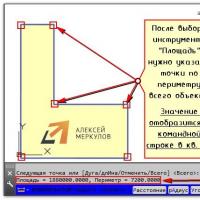
So, after selecting the command, you should specify points along the perimeter of the figure. The area value appears in the Command Line Log. The perimeter of the object will also appear there. Don't be alarmed by such large values. The thing is that the area is displayed in mm 2. A little later we’ll look at how to convert it to m2.

The sub-options of the “Area” command are of particular interest here:
- ABOUT OBJECTS- to display the area, you need to specify the contour of the closed figure;
- D add area- allows you to calculate the area of several objects at once. To do this, you need to activate this suboption, then go to the “objects” parameter and select closed shapes in the required quantity in the graphic field.
NOTE: Read about how to combine objects in AutoCAD into solid 2D primitives.
- Subtract area- the opposite action. Allows you to remove objects from previously selected ones to calculate the total area.
How to change area units in AutoCAD/AutoCAD?
So, we already know how to measure the area in AutoCAD, however, the values are displayed in mm 2 and this is not very convenient. In order to convert them into m2, which are familiar to us, we will use a quick calculator. To do this, just right-click in an empty space in the graphic space and select “QuickCalc” (see figure).

The command line log can be slightly enlarged by stretching its borders with the mouse. Next, find the required area/perimeter value, copy it (Ctrl+C) and paste the value into the calculator. Here you should work a little with the “Unit Conversion” list (see figure).

By clicking on the “+” sign next to “Unit Conversion”, you need to set the “Unit Type” by selecting “Area” from the list, and also change the value of the “Convert from” field to “Square millimeters”. In order for the converted value to be displayed in the corresponding field, simply click LMB inside this field (see figure).

As you can see, with this approach, the conversion of area units from mm2 to m2 is done automatically.
How to find out the area in AutoCAD through object properties?
In fact, area calculation in AutoCAD is performed automatically for standard closed primitives, such as circles, rectangles or, what is much more interesting, polylines, creating a contour, this value can be viewed in the “Properties” palette (hot key Ctrl+1).
NOTE: Converting area units from mm 2 to m 2 can be done by calling the quick calculator by clicking on the corresponding button in the “Area” field (see figure). The principle itself is similar to that described above.

When you move the mouse cursor, the coordinates of its position are simultaneously displayed. They (coordinates) are shown in the status line. To mark the coordinates of points on the monitor, you can either enter them manually from the keyboard or simply mark them using regular mouse clicks on the desired point. But before we do this, we need to understand what these coordinates are, how they are scaled and how they are displayed.
In the AutoCAD system, conventional units have been introduced as units of measurement. They are not tied to metric or any other units of measurement. But a number, say 20, is only a number 20, and it is entirely up to you what meaning you put into this number - 20 millimeters, 20 feet or 20 meters. Among other things, AutoCAD allows you to make some calculations: calculate areas, lengths of sections, etc. The result will also be displayed in conventional units of measurement. As a result of the above, you as a designer must adopt a certain measurement system for yourself (meters are meters, feet are feet) and adhere to it throughout the entire drawing development stage.
From all of the above, the question naturally arises about the scale that will be used in our drawing. Based on extensive experience in developing projects in the AutoCAD system, we recommend choosing a drawing scale of 1:1. Now let's explain why. Everything stems from the same convenience and the ability to calculate implicit and not specified, but required parameters, and when printing, the drawing can be scaled to any paper size convenient for us. But in order for all the coordinate settings to be displayed in a form that is readable for us, we need to enter some settings in AutoCAD using the Units command. To do this, select Format -> Units from the menu. As a result, a dialog box will appear on the screen with the ability to set parameters for units of measurement. Let's take a closer look at this dialog box.
- TYPE – type of units to be selected. There are only five of them: 1) Architectural (Architectural); 2) Decinal; 3) Engineering (Engineering); 4) Fractional; 5) Scientific. In Russia and the CIS the decimal type is mainly common, in the USA it is the architectural type.
- PRECISION - accuracy. In this setting, we need to enter the number of decimal places that are significant to us. BUT!!! Here ONLY THE ACCURACY OF DISPLAYING COORDINATES is set, and not the accuracy of drawing. For example, on the monitor you see coordinate 53.70, but you can specify a point with coordinates 53.69. To increase accuracy when drawing, you need to use, for example, coordinate input, but we’ll talk about that later.
- This parameter specifies the accuracy for angular quantities, such as radians, degrees, minutes, seconds.
- The direction of positive angle counting is set here (in the default settings this direction is counterclockwise), but if this direction does not suit you, you can change it in this parameter.
- Drag and Drop Scale – in this parameter, units are set for their binding to fragments of other drawings when they are transferred to our created project, but this ratio will only be used if certain commands are available, so this option must be used with caution.
After the listed parameters, the dialog box contains the familiar Ok, Cancel and Help buttons (we won’t dwell on them, everything is clear), but in addition to them, there is also a Direction button. With its help, we have the opportunity to set the direction from which the angles will be measured. The default direction is East - East (X-axis direction). But if necessary, this default direction can be changed.
So, let's summarize all of the above. In this lesson we learned how to set up a unit system for our drawings. If you use the wizard in the process of creating a new file (File -> New -> Use wizard), then actions similar to what we discussed in this lesson will be performed.
 Setting up an AutoCAD drawing
 Natasha Koroleva's husband flashed his buttocks Natasha Koroleva in contact group
 Cleaning up your C drive is a killer method for clearing junk from your computer.
 USB drive from laptop hard drive
 Managing pop-up windows in Yandex
 What to do if the computer does not see the printer The printer is detected as an unknown device
 Amendments to the rules for the provision of postal services have been approved in Russia